RHB FLUORO SYLLABUS DATA EXCERTS Created 2008 RT

RHB FLUORO SYLLABUS DATA EXCERTS Created 2008 RT 244 wk 4 / RT 255 Review

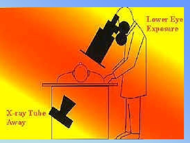
• • Ch 1 – pg 1 5% population have fluoro exams 53% GI tract (1996 ) 120 sec fluoro ~= ese 5 – 15 rads Comp to ABD ~= ese 100 - 500 mrads Fluoro used for dynamic studies USING FLUORO TO POSTION PATIENTS PRIOR TO TAKING FILM IS PROHIBITED • Must have fluoro permit or Supervisor & Operators Certificate from state

• • • Ch 2 - review all outlined Inc factors directly influencing dose: Ma, Fluoro (0. 5 – 5 ) (usually 1 – 3 ma) Spot film ma (100 – 200) Kvp ( 80 -130) FOR FLUORO collimaiton ALWAYS SMALL AS POSSIBLE Filtration 3. 0 mm AL for 125 -150 kvp time, (less is better) – 5 Min audible alarm Doubling time = doubling exp to patient Pulsed fluoro vs continuous Image receptor speed (FASTER) 8: 1 grid ratio fluoro

• • • Ch 2 LIH or last image hold High kvp / low ma Lower frame rate Long tube to patient distance – 18 “ preferred in stationary (15” minimum) – Mobile – 12” minimum • Short II to patient distance – moving II 12 to 18 “ away ↑ dose by (30 -45%) • Dead Man Switch – foot pedal

• • • ALLOWABLE EXPOSURE RATES Before 1974 w/o AEC = 5 R/min After with AEC Regular mode = 10 R/ hr BOOST/MAG mode = 20 R/hr The table top intensity should not exceed 2. 2 R/min for each m. A of current at 80 k. Vp • ROOM LIGHTING • Ambient light low – see image better – less pt dose • Bright light reduced eye to resolve detail • Otherwise increasing kvp/mas will increase pt dose

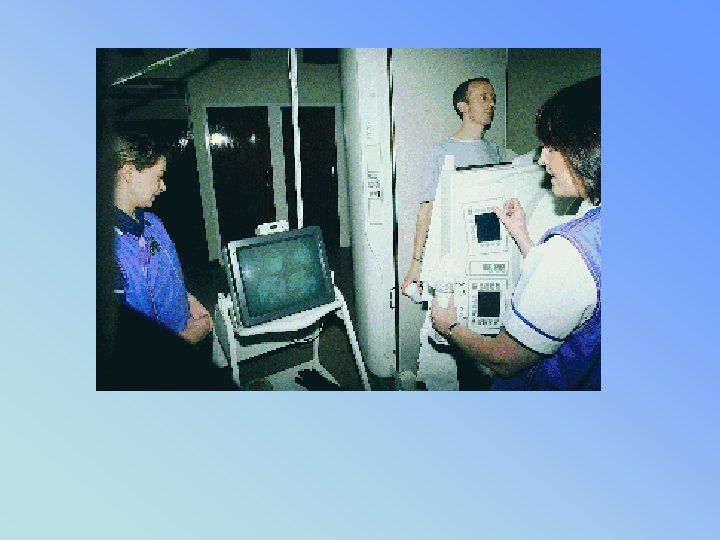
Light Levels and Fluoroscopy

• II – 2 mm lead equiv = Primary Barrier • Interlocked – prevents exposure when parked • SHIELDING requirements (pg 5) • BUCKLY SLOT COVER –. 25 mm lead – bucky moved to end of table • CURTAIN – in place. 25 mm lead – w/o dose can be 500 mrads/hr to operator – Not requried on c-arm mobile units

BUCKY SLOT COVER. 25 MM LEAD

Lead curtain & dose reduction

• • • Image intensifiers – reduces pt dose Review parts & function BG = MG x FG Quantum Mottle (not enough photons) Blotchy, grainy appearance – Caused by too little exposure – Most commonly remedied by increasing m. A

Functioning of Image Intensifier

Units of measurement • INPUT PHOSPHOR – IS MEASURED IN _________________ • OUTPUT PHOSPHOR IS MEASURED IN • _______________

BG = MG X FG • FLUX GAIN – increase of light brightness due to the conversion efficiency of the output screen • 1 electron = 50 light photons is 50 FG • Can decrease as II ages • Output phosphor almost always 1 inch • Zinc cadnium phosphot • Flux gain is almost always 50

Image Intensifier • VACUUM TUBE • ENCASED IN A LEAD HOUSING • = 2 MM PB • (PRIMARY BARRIER)
 – Equipment")
Contrast • Contrast – – Subject – changed by contrast media (PE) – Equipment (camera tube, settings on monitor) • Controlled by amplitude of video signal • Affected by: – Scattered ionizing radiation – Penumbral light scatter
 1024 (newer digital) – Ability to")
• Resolution – 525 line TV (old) 1024 (newer digital) – Ability to resolve objects (detail) – Measured in lp/mm – MTF – expression of resolution for imaging system (modulation transfer function) • Distortion – size, shape (pg 9) – PINCUSION may comprise 8 – 10 % of image area

Image distortion PINCUSHION EFFECT

Size Distortion • Affected by same parameters as static radiography – Primarily OID – Can be combated by bringing image intensifier as close to patient as possible

Shape Distortion • Geometric problems in shape of input screen – Concave shape helps reduce shape distortion, but does not remove it all – Vignetting or pin cushion effect

• Pg 9 • LAG – blurring occurs from moving II too quickly – can’t capture photons – (amt of time for camera tube to capture) • VIGNETTING – fall off of brightness at periphery of image = loss of brightness • II TUBES = MULIT MODE • BI FOCUS (2 sizes) Tri. I (3 sizes) • Smaller surface area= MAG MODE • ↓ suface area ↑ mag = ↑ patient dose • II ~= 4 lp/mm Mag ~= 6 lp/mm

Intensifier Format and Modes Note focal point moves farther from output in mag mode

• Pg 9 • • • TV – closed circuit system via video cables TV CAMERA/ PICK UP TUBES: VIDICON PLUMBICON IMAGE ORTHOCON • TRANSFERS IMAGE FROM OUTPUT PHOSPHOR TO TV MONITOR • CONNECTED BY FIBER OPTICS
 • VIDICON tube uses antimony trisulphide • PLUMBICON")
TV camera and video signal (II) • VIDICON tube uses antimony trisulphide • PLUMBICON tube made out of lead oxide,

VIDEO/CAMERA TUBE • VIDICON MOST COMMOM – LOWEST PATIENT DOSE • PLUMICON – BETTER RESOLUTION • ORTHOCON – VERY $$$$ – BEST RESOLUTION … but…. • (II & camera tube combined (not used)

Type of TV camera F VIDICON TV camera F improvement of contrast F improvement of signal to noise ratio F high image lag F LOWER PATIENT DOSE F PLUMBICON TV camera (suitable for cardiology) F F lower image lag (follow up of organ motions) F higher quantum noise level CCD TV camera (digital fluoroscopy) F digital fluoroscopy spot films are limited in resolution, since they depend on the TV camera (no better than about 2 lp/mm) for a 1000 line TV system
 TV Camera")
Vidicon (tube) TV Camera

• TV CAMERA TUBE – • 525 = TOTAL # OF SCAN LINES

Basic Componets of “old” Fluoroscopy “Imaging Chain” Primary Fluoro TUBE EXIT Radiation PATIENT Radiation Cassette 105 Photospot Image Intensifier VIDICON Camera Tube ABC CONTROL UNIT Fiber Optics OR Image Recording Devices CINE TV

• PG 10 • CAMERA CONTROL UNIT • Synchronizes the video signal between camera & monitor • TV –MONITOR – CRT – Cathode Ray Tube – Much larger than camera tube – but similar function – The electrons are synchronized by the control unit – so they are of the same intensity and location as the electrons generated by the pick up (camera) tube

• CINE/ CINEFLUORGRAPHY PG 10 • Synchronized with camera shutters – no exp while closed – Movie camera intercepts image • • 16 mm and 35 mm formats Record series of static exposures at high speed 30 – 60 frames per second Offer increased resolution – At the cost of increased patient dose • FRAMING FREQUENCY – Division of 60 (7. 5, 15, 30, 60, 90, 120) – ↑# frames ↑ patient dose – 2 mr/frame ~30 f/sec

• VIDEO DISC RECORDING • (like a laser disc – size of an LP record ? ? ? ) • Combines radiography with fluoro • Image is stored as a single frame on a video disc recorder - newer uses CD • 95% dose reduction when utilizing video disc recording during fluoro • VIDEO TAPE RECORDING • Provides a permanent record w/o ↑ pt dose • Instant play back - Real time images • Poor image quality

• • SPOT FILMS – CASSETTES BETWEEN PT & II ↑ Ma (100 -200) ↓ time High resolution • • • PHOTOSPOT – ½ - 1/3 DOSE OF FILM CASSETTES TAKEN FROM OP OF II ↑ Ma , ↓ time (LESS THAN CASSETTE) ↓ image quality than cassettes PG 11

CASSETTE SPOT FILMING vs PHOTOSPOT FILMING • • • First type of recording used 9 x 9 cassettes then later up to 14 x 14 9 on 1, 4 on 1, 2 on 1 Delay while filming (anatomy still moving) Radiographic m. A - must boost up to 100 – 200 m. A for filming And moving cassettes around inside tower Higher patient dose Replaced by Photospot (f/sec) filming
 filming – • Set at")
CASSETTE SPOT FILMING vs PHOTOSPOT FILMING • Photospot (f/sec) filming – • Set at control panel from 1 f/sec – 12 f/sec • Used for rapid sequence: – Upper Esophogram – Voiding Cystourethrograms (Peds) • Lower patient dose

• ACCESSORIES – • GONAD SHILEDS – 0. 5 MM PB • GRIDS - 8: 1 RATIO • CASSETTES – front – low z# – Higher speed = lower pt dose = lower resolution
 = Scatter to RT DOSE influenced by: Physique Pathology Habitus Type of")
PATIENT (BODY) = Scatter to RT DOSE influenced by: Physique Pathology Habitus Type of tissue exposed Tissue density REMNANT RADITIATION hits II (review ESE – tube, II)

• EQUIPMENT REVIEW • PG 16 – 26 • REVIEW OF FORMULAS TO KNOW:
")
Intensifier Performance Conversion factor is the ratio of output phosphor image luminance (candelas/m 2) to xray exposure rate entering the image intensifier (m. R/second). • Very difficult to measure: no access to output phosphor • No absolute performance criteria
 BG = Minification Gain x Flux Gain • m. G")
Intensifier Brightness Gain (BG) BG = Minification Gain x Flux Gain • m. G = (Input Diameter )2 (Output Diameter)2
: Produced by accelerating the photoelectrons across a")
Intensifier Brightness Gain • Flux Gain (FG): Produced by accelerating the photoelectrons across a high voltage (>20 ke. V), thus allowing each electron to produce many more light photons in the output phosphor than was required to eject them from the photcathode. • Summary: Combining minification and flux gains:

MAG MODE FORMULA IP OLD SIZE IP NEW SIZE = %mag

PT dose in MAG MODE IP OLD SIZE IP NEW SIZE = ↑pt dose 2 2
 I. I. Input Screen Electrode E 1 Electrode")
The image intensifier (I. I. ) I. I. Input Screen Electrode E 1 Electrode E 2 Electrode E 3 Electrons Path I. I. Output Screen Photocathode +

k. V X Ray TUBE FILM PM VIDICON REFERENCE CONTROLLER k. V GENERAL SCHEME OF FLUOROSCOPY

Modern fluoroscopic system components

vignetting • • Falloff of brightness at edges of TV screen Unequal mag can cause unequal illumination Center of screen is brighter than periphery Resolution is also better in center End of Wk 4 RHB review

• PG 23 • VEILING GLARE • Scatter in the form of x-rays, light & electrons can • reduce contrast • of an image intensifier tube.

• PG 23 • ABC • Automatic brightness control allows Radiologist to select brightness level on screen by ↑ k. Vp or ↑ m. As • Automatic dose control • Located just beyond the Output Phosphor • Will adjust according to pt thickness
 output phosphor")
Automatic Brightness Control • Monitoring Image Brightness – Photocell viewing (portion of) output phosphor – TV signal (voltage proportional to brightness) • Brightness Control: Generator feedback loop – k. Vp variable – m. A variable/k. V override – k. V+m. A variable – Pulse width variable (cine and pulsed fluoro) – less dose with pulsed vs continous fluoro

• ABS - look at bullets pg 23 – Hold image brightness – Ignore info at edge (vignetting) – Keep pt ese to less than 10 R/min reg – Can shut off – use manual mode

• Pg 24 ABS • Variations with X-ray factors: • Brightness of image varies directly with m. A & approx the square of k. Vp – k. Vp ↑ 80 to 88 – (10% change) 10 2 = 100% ↑ in brightness • k. Vp ↑ = ↓ image resolution but also • ↓ patient dose • ∆ USE optimal k. Vp: • to ↑ image resolution & ↓ patient dose

TV MONITOR Pg 27 TV Image Quality

• TV monitor made of 1000’s of tiny dots of differing brightness – arranged in horizontal scan lines • 525 system= total # of line – regardless of screen size • (one dot at a time transmitted from tube) • 1000+ systems = double resolution • Resolution/quality determined by: • affected by # of scan lines = BANDPASS of system • Horizontal resolution / Vertical resolution • Contrast / Brightness / Lag

TV SYSTEMS • Images are displayed on the monitor as individual frames – which tricks the eye into thinking the image is in motion (motion integration) • 15 f/sec – eye can still see previous image • 32/f harder to detect with eye • Weakest Link - 2 lp /mm resolution • No Permanent Record (cannot make dx) • Real Time

• Bandwidth or Bandpass- total # of cycles/sec – Product of scan lines, scan rate & frequency • • • Horizontal resolution – resolve dots ↑ bandwidth = camera tube to turn off & on more times/sec ∆ ↑ bandwidth ↑ resolution

TV RESOLUTION-Horizontal • Along a TV line, resolution is limited by how fast the camera electronic signal and monitor’s electron beam intensity can change from minimum to maximum. • This is bandwidth. For similar horiz and vertical resolution, need 525 changes (262 ½ • full cycles) per line. • Example (at 30 frames/second): 262 cycles/line x 525 lines/frame x 30 frames/second

KELL FACTOR pg 28 VERTICAL RESOLUTION ABILITY TO RESOLVE OBJECTS SPACED APART IN A VERTICAL DIRECTION MORE DOTS(GLOBULES) = MORE SCAN LINES = MORE/BETTER RESOLUTION • RATIO OF VERTICAL RESOLUITON • # OF SCAN LINES • KELL FACTOR FOR 525 LINE SYSTEM • IS 0. 7

• • More on camera tubes – pg 28 Plumbicon - ♥ cath Image Orthocon CCD – replaced conventional tubes – Fast discarge time – eliminates image lag – Repeat info pg 29 -30

• CINE – FRAMING & PT DOSE PG 31 • • Number of frames per second Cine – division of 60 (7. 5, 15, 30, 90, 120) Organ if interest determines f/s rate Patient exposure Under framing Exact framing Overframing Total overframing CINE RESULTS IN APPROX 10 x HIGHER DOSE THAN CONV FLUORO

• • • STATIC IMAGE RECORDING PG 31 -32 Video Disk – LIH (95% dose ↓) ABD fluoro ~ 10 R ↓ to 500 m. R Speed 1 image/sec – 30 image/sec Best to use in “real time” not needed PHOTOSPOT 70 MM – 105 MM FILM LARGER FILM = ↑ IMAGE QUALITY ABOUT ½ DOSE THAN CASSETTES HAVE ↑ IMAGE QUALITY • ? ? BOTTOM OF PG 32 (20 -50 X ↑) ? ? ?

• • • DIGITAL FLUORO IMAGE CONVERTED ADC – DAC CAN PRINT IMAGE ON FILM ADVANTAGES: (pg 34) (more later) Mask –mode subtraction Post processing • ? ? Resolution of digital images lower than film? ?
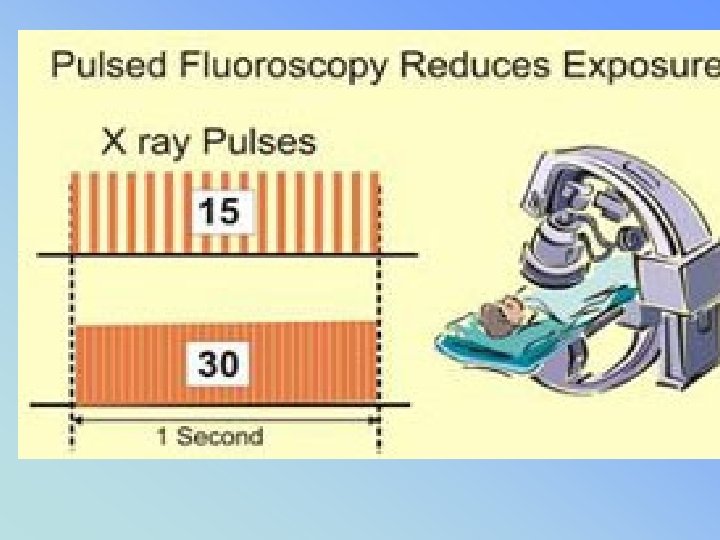

• • Pg 34 – 35 PULSED FLUORO - ↓ PT/RT DOSE LOWER FRAME RATE NOT USED FOR MOVING OBJECTS • • • HIGH LEVEL BOOST (Interventional) Uses 10 -20 m. A (40 m. A) 10 – 20 X higher pt dose 10 – 50 R/min dose rate at tabletop (20 R / MIN – 1994 regs limits w/o recording devices such as video )
 OPTICAL MIRROR – BEST BUT NOT")
RECORDING DEVICES RESOLUTION P 542 (3 rd ed) OPTICAL MIRROR – BEST BUT NOT PERMANENT RECORDING MEDIUM • SPOT FILM CASSETTES 6 LP/MM • PHOTO SPOT 105 / 70 • CINE 35 MM / 16 MM • DIGITAL (? ) (VS FILM) • VIDEO – VIEWING REALTIME • VIDEO TAPE - PLAYBACK

8 th Digital static real-time 7 th highest Pg 35 short
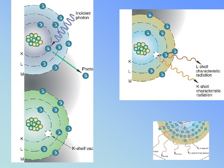
 • Works because of photoelectric effect • (absorbtion")
• Contast Media (pg 36) • Works because of photoelectric effect • (absorbtion of higher z# - shows differences in contrast of structures
 ↑ ↑ directly")
• Ch 4 – pg 37 Fluoro Exam (repeat info) ↑ ↑ directly proportional to dose (pt & Rt) • Operator dose & pt dose • Image brightness & rad dose • m. A, kvp, collimation, filtration, time, TPD ↑ ↓indirectly proportional to dose (pt & Rt) • Poor image quality • Room lighting • Tabletop absorbtion
 Patient & Operator")
• Ch 4 – pg 37 Fluoro Exam (repeat info) Patient & Operator (MD/RT)shielding: • Gonad Shield • Bucky slot cover • 3 φ generators m. A ↓from 5 to 3 = dose ↓ 40 % – image will not be brighter if field size is larger

• Pg 38 • ↑ k. Vp – ↑ internal dose of organs (slight) • But ↓ ESE dose • Collimation • Must be seen when carriage is 14” above table top & shutters fully open • Open collimation - ↑ pt dose & • ↑ patient integral dose

• Pg 39 Integral Dose • Total energy absorbed from the beam • Unit is GRAM RAD (1 gm rad = 100 ergs)
 Minimum 2. 5 mm al eq")
• • • Pg 39 Filtration (repeat) Minimum 2. 5 mm al eq Fluoro – 3 mm al eq Reduces low energy scatter Improves quality of beam Inherent + added Fluoro kvp ranges from 80 – 120 TABLETOP INTENSITY OF FLUORO – NOT EXCEED 2. 2 R/MIN /MA AT 80 KVP

• PG 39 • HVL – • Thickness of material to reduce exposure by ½ • Also used for sheilding • Ex: • To reduce 100 mr/min to 25 mr/min – need 2 HVL • ? ? How many for 10 mr/min ? ? ?

• Pg 40 Exposure Time • ↓ beam on time = ↓ pt exposure • 5 “looks” @ 12 sec / look ~ =1 min exposure • ~= 400 mrad / look (@ 5 R/min) • • • ? 5 min timer – audible alarm Allowable Exposure Rates – repeat 1974 with AEC 10 R/min; 20 R/min Boost without AEC 5 R/min

Recording the Patient DOSE FLUORO BEAM ON TIME

• Pg 41 • AEC – • Must MONITOR tube current & potiental at least ONCE EACH WEEKLY • (QC – recorded DAILY) • Using a PHANTOM (H 2 O or lucite) – Physicist 1/year w/o aec once/3 years
 • 18”")
SSD – TUBE TO SKIN DISTANCETPD – • FIXED UNITS (pg 41) • 18” PREFERRED • 15 “ MINIMUM MOBILE UNITS ( C-ARMS) • 12’ MINIMUM TPD • Increasing TPD 12 – 18 “ • ESE is ↓ 30 % (45%)? ? ?

• • • Lighting. Visual Acuity – percieve fine detail ↓ room light ↑ acuity Photopic 10 x greater than Scotopic Normal viewing 12 – 15 inches Integration time – recognition time is 0. 2 sec
 pg 42 -43 • Gonadal • Bucky slot cover •")
• Sheilding (again!) pg 42 -43 • Gonadal • Bucky slot cover • 3 φ generators note bottom of paragraph pg 43 = no difference when tech adjusted
 Ch 6 – PEDS More")
• • Ch 5 – bullets (repeat info) Ch 6 – PEDS More sensitive to radiation Motion – problem with peds Artifacts - diapers Immobilization AEC – contrast filled - may over expose (ex cystogram- turn off AEC)
 Collimation reduced (can dramatically ↑ dose")
• • Ch 6 – PEDS (more) Collimation reduced (can dramatically ↑ dose when open) Shield gonads when possible Photospot best recording for children Persons holding – scatter use sheilds Monitor if frequently exposed” Close II to pt

KEEP I. I. CLOSE TO PATIENT

RADIATION PROTECTION The Patient is the largest scattering object • Lower at a 90 DEGREE ANGLE from the patient + PRIMARY BEAM AT 1 METER DISTANCE • 1/1000 OF INTENSITY PRIMARY XRAY or 0. 1%
 Bullets Space to prevent")
• • Ch 7 – Mobile Equipment (more later) Bullets Space to prevent closer than 12” (30 cm) Provide sheilding for ALL Ch 8 Responsibilities of Supervisor Fluoro – Permit Holders only operate

PERSONNEL PROTECTION pg 50 • • PROTECTIVE APRONS – 0. 25 PB = 97% ↓ TO SCATTER 0. 5 PB = 99. 9% ↓ TO SCATTER THYROID SHEILDS (0. 25 & 0. 5) GLOVES (0. 25 & 0. 5) Hanging screens, Sliding Sheilds Lead glasses (interventional)

• • Display of Documents CRT/ FLUORO – MUST BE DISPLAYED NOTICE TO EMPLOYEES Dose – Recorded monthly/quarterly – DOSE LIMITS – WHOLE BODY – EYES – EXTREMITIES (BELOW ELBOW/KNEES)
 indefinitely")
Report at least every quarter Preserved for a minimum of 3 years (employer) indefinitely - individual

RHB “RULES” RHB RP PG 61 • LICENTIATES OF THE HEALING ARTS (MD, DO, DC, DPM) • MUST HAVE A • RADIOLOGY SUPERVISOR & OPERATORS PERMIT & CERTIFICATE • TO OPERATE OR SUPERVISE THE USE OF X-RAYS ON HUMANS • SUPEVISORS MUST POST THEIR LICENSES
 (Fluoro – pg 53 & RP Syllabus –")
RHB NOTIFICATION (EXP IN 24 HOURS) (Fluoro – pg 53 & RP Syllabus – pg 68) • Equipment Purchase – 30 days • Change of Name /Address 30 days • Illegal to Deliberate Expose individual • ALL XRAYS MUST BE ORDERED BY A PHYSICIAN • VERBAL OR WRITTEN PRESCRIPTION
 Fluoro Permit")
• • • Ch 9 - pg 56 (more repeated info) Fluoro Permit Required ALARA: Know exam Remove unecessary people COMMUNICATE /COLLIMATE/SHIELD – ↓motion/ artifacts • TECHNIQUE ↑ kvp ↓mas (practical) • POSITIONING – AP/PA & GOOD!

• • Pg 57 Direct Supervision Permit Holders: Review list Restrictions: Perform w/o order Make a dx, telling to patient

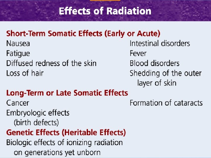
• Ch. 10 – Health Effects • Somatic Dose – Measured bone marrow, skin, thyroid, gonad – (not when organ is sheilded) • Genetic Dose – Future generations Ch 11 – Biologic Effects (other class)
")
RHB – Rad Prot – CH. IX p 51 • ALARA (no minimum threshold) • STOCHASTIC EFFECTS – NON TRESHOLD (CA + GENETIC) • NON STHOCAHSTIC (DETERMINISTIC) SEVERITY OF EFFECTS VARIES WITH RADIATION DOSE (THRESHOLD) (CATARACTS, SKIN, BONE MARROW, STERILITY

• • • Ch 11 – Biologic Effects Dose rate to tissue Total dose Type of cell irradiated Latent period (no visable effect)
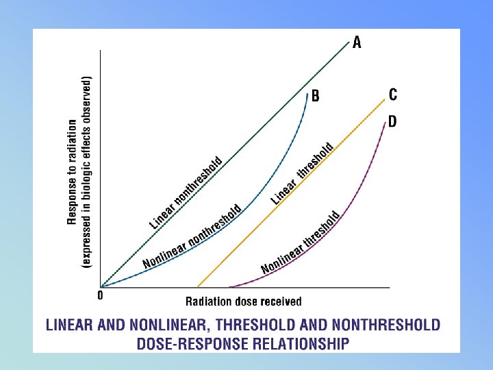

SOMATIC & GENETIC STOCHASTIC VS NON STOCHASTIC • A = STOCHASTIC • “CHANCE” EFFECTS GENETIC, LEUKEMIA, CANCER DIAGNOSTIC RADIOLOGY B= NON-STOCHASTIC THRESHOLD EFFECTS DETERMINISTIC SOMATIC EFFECTS SKIN ERYTHEMA, CATARACTS, STERILITY RAD -MALIGNANCIES

• 1 – LINEAR – NON THRESHOLD DIAGNOSTIC RAD • 2 – LINEAR THRESHOLD • 3 – SIGMOIDAL RAD THERAPY

 • Lymphocytes most sensitive • Pg")
• Cell Sensitivity to Radiation (pg 64) • Lymphocytes most sensitive • Pg 65 • Radiation induced cancers – • Bone #1, Breast (last) ? ?

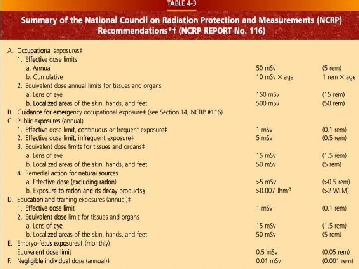
PERSONNEL PROTECTION CH 12 PG 68 Permissible Occupational Dose • Annual dose: • 5 Rem / year 50 m. Sv / year • Cumulative Dose • 1 rem x age 10 m. Sv X age

Personnel Monitoring Devices • Film Badges • TLD • Pocket Dosimeter • Ring Badge

Personnel Monitoring Devices PG 68 -75 ACCURACY • • Film Badges TLD POSL Pocket Dosimeter • Ring Badge • • 10 mrem 5 mrem 1 mrem ?

fb • FILM BADGE • MONTHLY • TLD/POSL • QUARTERLY • POCKET • DAILY DOSIMETER

MEASUREMENT • POCKET DOSIMETER • NOT ACCURATE • Or permanent

Gonad shielding & dose • ♀ receive 3 x more dose than • ♂ for pelvic x-rays • 1 mm lead will reduce exposure (primary) by about 50% ♀ • by about 90 – 95 % ♂

• It may be advisable to wear a second personal monitoring device if a worker is: • 1. performing routine radiological procedures • 2. pregnant • 3. a student • 4. performing special procedure • examinations

Q = t x תּ CUTIE PIE

Ppg 75 & 76 Monitoring requirments

• HIGH RADIAITON AREA – • 100 m. Rem ( 0. 1 rem / (1 ms. V) – @ 30 cm from the source of radiaton • RADIAITON AREA – • RHB: 5 m. Rem ( 0. 005 rem / (. 05 ms. V) – @ 30 cm from the source of radiation • PUBLIC 2 mrem per week* (STAT)
 •")
MONITORING PG 75 • CONTROLLED AREA – Used by occupationaly exposed personnel (monitored) • 100 mrem / WEEK • UNCONTROLLED AREA – PUBLIC • 2 mrem per week*

• • • APPENDIX #1 – THE EYE PHYSIOLOGY #2 COMPETENCY SHEET # 3 Units of Dose #4 Time Distance Sheilding #5 Rad Innjury #6 Pregnancy #7 Occupationally Exposed Female # 8 Gonad Sheilding

• MORE – • App # 9 Overview of Regs 89 -96 • QC pg 97 – 113 (more later) • Daily / Semi Annual / Annual reqs • App 12 ISOEXPOSURE CURVES – pg 115 -117 – ORGAN DOSES – PG 118 – MORE REGS - to pg 125 – Glossary 125 - 160

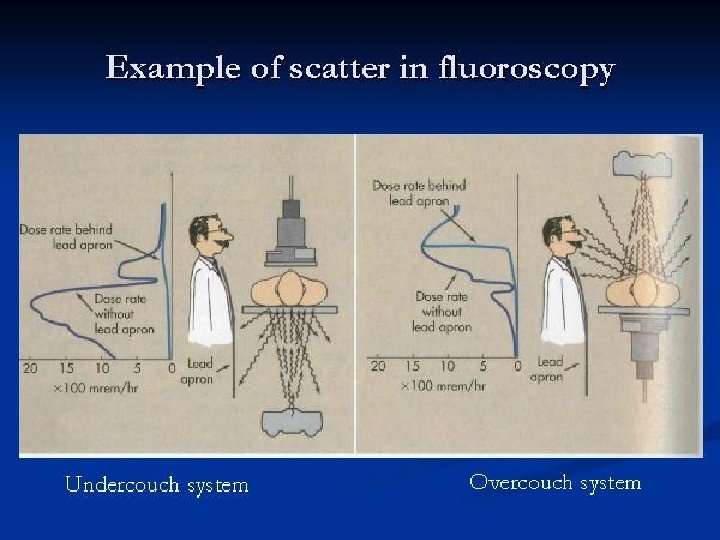
Over vs under the table fluoro tubes pg 116 dose to operator

Units of Dose – App #3 pg 79 100 R = 1 C/kg 1 Rad = 1/100 Gray 1 Rem =. 01 Sievert (Rad + QF = REM) 1 REM = 10 m. Sv 1 Rem = 1000 m. Rem

 • Baby – (500 m.")
Pregnancy & Embryo Mother – occupational worker (5 rem) • Baby – (500 m. Rem) • . 5 rem/ year. 05 rem/month • 5 m. Sv / month
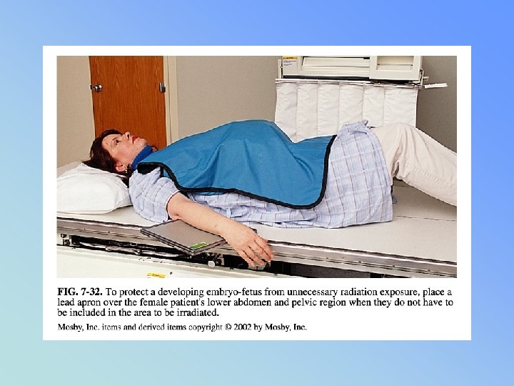

• PREGNANCY • Pregnant Patient - PG 84 Under 5 rad – negligible risk Risk increases above 15 rad Recommend abortion (spontaneous) 25 rad • (“Baby exposure” approx 1/50 ? of ESE) • www. ntc. gov/NRC/RG/08/08 -013. html
 • HIGHLY RADIOSENSITIVE = DEPENDS OF STAGE")
GERM CELLS in Females (present at birth) • HIGHLY RADIOSENSITIVE = DEPENDS OF STAGE OF DEVELOPMENT • Mature ovum do not divide frequently • (20 -30 yrs old - least sensitive) • Immature very sensitive • If exposed ova meets sperm – may contain damaged chromosomes – passing genetic damage to offspring = • CONGENTIAL ABNORMALITIES

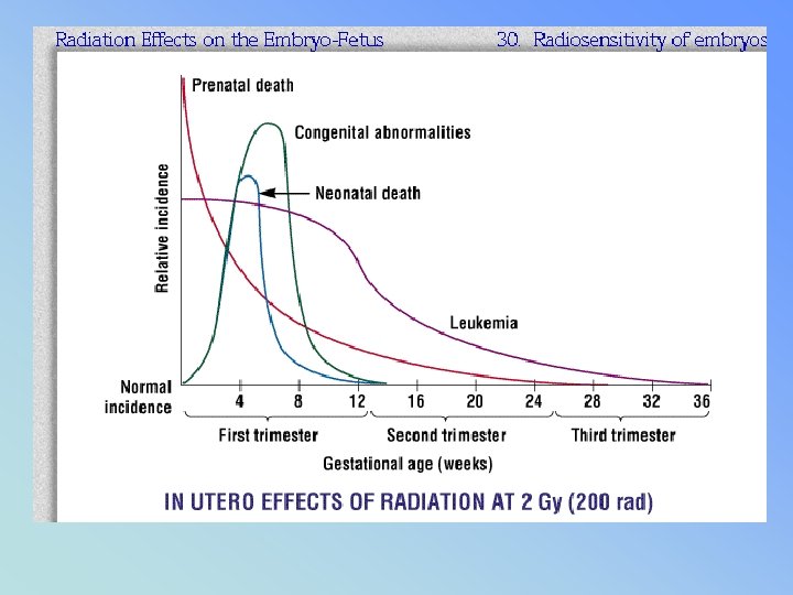
FETAL EFFECTS • Most sensitive in first trimester - large number or stem cells • First two weeks – death by spontaneous abortion • A dose of 10 rad (. 10 gy) - expected death rate occurs at 10% higher than that would normally exist

Declared Pregnant Worker • Must declare pregnancy – 2 badges provided • 1 worn at collar (Mother’s exposure) • 1 worn inside apron at waist level

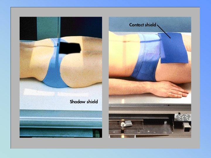
GONAD SHIELDING pg 87 • MUST BE. 5 MM OF LEAD • MUST BE USED WHEN GONADS WILL LIE WITHING 5 CM OF THE COLLIMATED AREA (RHB) • FLAT / CONTACT / SHADOW

RHB- RAD PROT SYLLABUS

• HIGHLIGHTS RE FLUORO & RAD PROT • PG 43 - lymphocytes most depressed ♀ OVARIES = TEMP STERILITY • 30 rads ♂ TESTIES = TEMP STERILITY • 300 rads • PG 45 – REPEAT INFO

Gonad shielding & dose • ♀ receive 3 x more dose than • ♂ for pelvic x-rays • 1 mm lead will reduce exposure (primary) by about 50% ♀ • by about 90 – 95 % ♂

ROOM SHIELDING • PRIMARY SHIELD – • PRIMARY BEAM DIRECTED AT WALL • 1/16 LEAD - 7 FEET HIGH

ROOM SHIELDING • • • SECONDARY – NO PRIMARY BEAM 1/32 LEAD CONTROL BOOTH (SECONDARY) BEAM SCATTERS 2 X BEFORE HITTING LEAD WINDOW – 1. 5 MM LEAD EQ

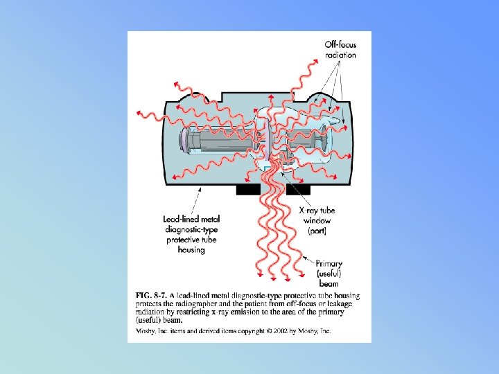
• OFF FOCUS RADIATION • & Stray Radiation • Pg 51 RHB syllabus

LEAKAGE RADIATION may not EXCEED • TUBE HOUSING 100 m. R / HR @ 1 meter

OFF FOCUS RADIATION
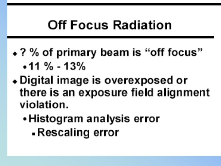
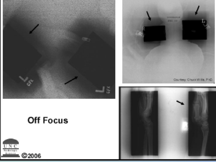

SHADOW OF SOMEONE’S HEAD = OFF FOCUS FROM TUBE

PERSONNEL PROTECTION pg 52 RP RHB • STANDING BEHIND A PROTECTIVE PRIMARY (1/16 TH pb) BARRIER: • PRIMARY RADIATION EXPOSURE – 99. 87% REDUCED • PORTABLE BARRIER = 99 % REDUCTION

• PERSONNEL PROTECTION pg 52 RP RHB • SCATTER RADIATION • . 25 PB = 97 % ↓ • 0. 5 MM PB = 99% ↓
 • Appendi. X # 9 ESE DOSE RATES")
• (VENIPUNCTURE = PG 64) • Appendi. X # 9 ESE DOSE RATES PG 84 • PG 87 NOMIGRAM

Why did the bunny die? ? BUNNY A • Received 200 rads BUNNY B • Received 200 rads

Why did the bunny die? ? BUNNY A 200 rads of X-RAY = 200 RADS BUNNY B 200 rads of alpha = 4000 rads

The END – Be Careful !!!
- Slides: 147