
RFQ Development for FETS Simon Jolly Imperial College
- Slides: 24
RFQ Development for FETS Simon Jolly Imperial College 16 th December 2009
FETS RFQ Development • FETS will utilise a 4 m-long, 324 MHz four-vane RFQ channel, consisting of four resonantly coupled sections. • RFQ focuses beam from LEBT and accelerates it to 3 Me. V, ready for Chopper/MEBT. • 4 -vane cold model showed agreement between CST simulations and bulk RF properties. • Previous beam dynamics simulations, based on field maps produced with a field approximation code, provide a baseline for the new design. • Novel design method currently under development to combine CAD and electromagnetic modeling with beam dynamics simulations in GPT. 16/12/09 Simon Jolly, Imperial College 2
Previous RFQ Design Method • RFQ parameterised by a and m parameters for modulations, r for vane radius and L for cell length (see following slide). • These parameters optimised by iteratively solving Kapchinsky-Teplyakov (K-T) equations. • Alan wrote custom code (RFQSIM) to generate RFQ parameters for both 4 -rod and 4 -vane RFQ’s: results compare favourably to other codes (eg. PARMTEQM). • RFQSIM used to successfully design ISIS 665 ke. V RFQ. • These parameters handed directly to Frankfurt for RFQ manufacture. 16/12/09 Simon Jolly, Imperial College 3
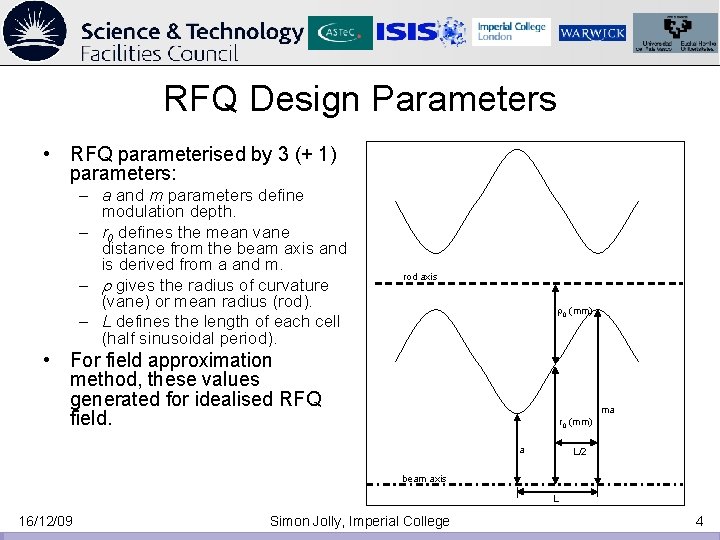
RFQ Design Parameters • RFQ parameterised by 3 (+ 1) parameters: – a and m parameters define modulation depth. – r 0 defines the mean vane distance from the beam axis and is derived from a and m. – r gives the radius of curvature (vane) or mean radius (rod). – L defines the length of each cell (half sinusoidal period). rod axis r 0 (mm) • For field approximation method, these values generated for idealised RFQ field. ma r 0 (mm) a L/2 beam axis L 16/12/09 Simon Jolly, Imperial College 4
FETS Integrated RFQ Design • Would like to have a method of designing RFQ where all steps are integrated: – Engineering design. – EM modelling. – Beam dynamics simulations. • Integrating design steps allows us to characterise effects of: – Fringe fields and higher order modes. – Particular CNC machining techniques and options on beam dynamics. 16/12/09 Simon Jolly, Imperial College 5
RFQ Design Stages 16/12/09 Simon Jolly, Imperial College 6
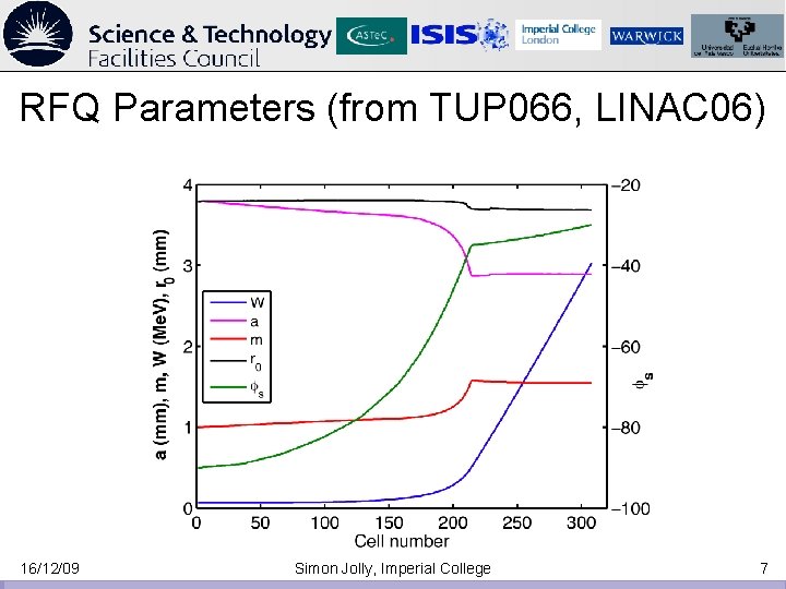
RFQ Parameters (from TUP 066, LINAC 06) 16/12/09 Simon Jolly, Imperial College 7
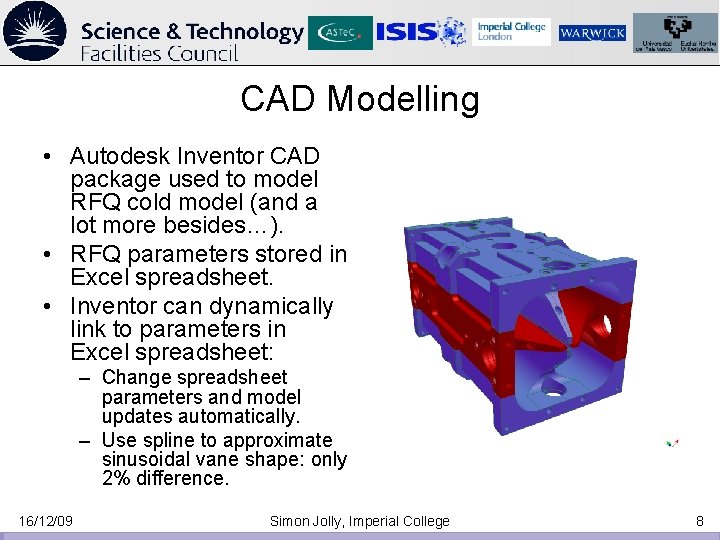
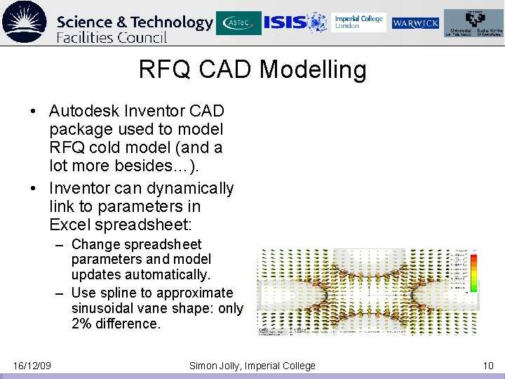
CAD Modelling • Autodesk Inventor CAD package used to model RFQ cold model (and a lot more besides…). • RFQ parameters stored in Excel spreadsheet. • Inventor can dynamically link to parameters in Excel spreadsheet: – Change spreadsheet parameters and model updates automatically. – Use spline to approximate sinusoidal vane shape: only 2% difference. 16/12/09 Simon Jolly, Imperial College 8
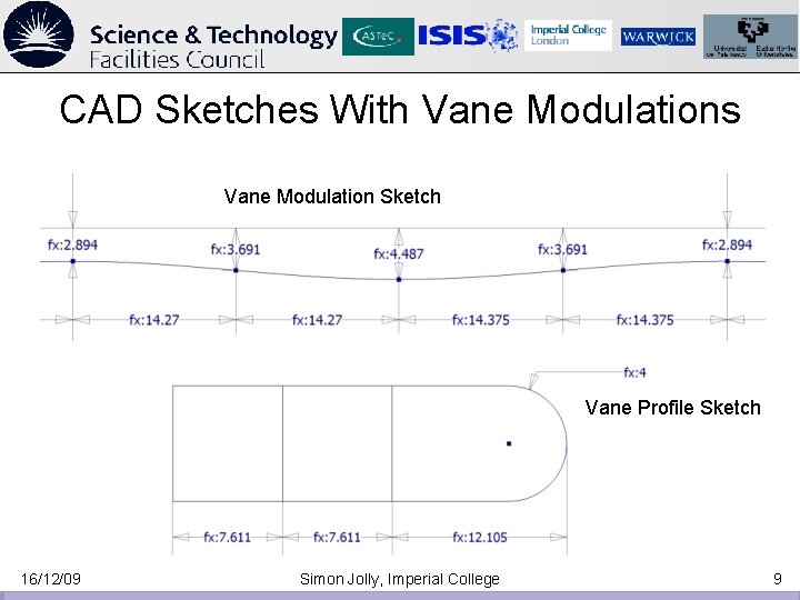
CAD Sketches With Vane Modulations Vane Modulation Sketch Vane Profile Sketch 16/12/09 Simon Jolly, Imperial College 9
RFQ CAD Modelling • Autodesk Inventor CAD package used to model RFQ cold model (and a lot more besides…). • Inventor can dynamically link to parameters in Excel spreadsheet: – Change spreadsheet parameters and model updates automatically. – Use spline to approximate sinusoidal vane shape: only 2% difference. 16/12/09 Simon Jolly, Imperial College 10
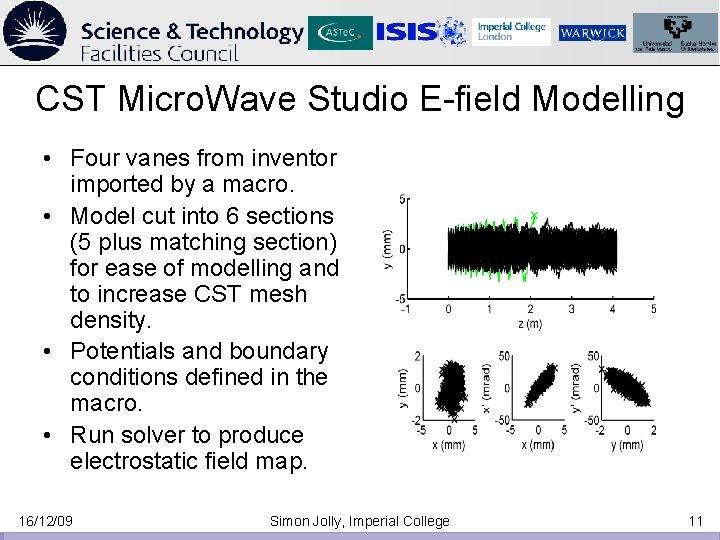
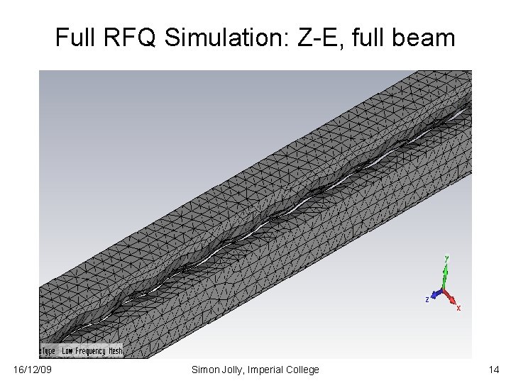
CST Micro. Wave Studio E-field Modelling • Four vanes from inventor imported by a macro. • Model cut into 6 sections (5 plus matching section) for ease of modelling and to increase CST mesh density. • Potentials and boundary conditions defined in the macro. • Run solver to produce electrostatic field map. 16/12/09 Simon Jolly, Imperial College 11
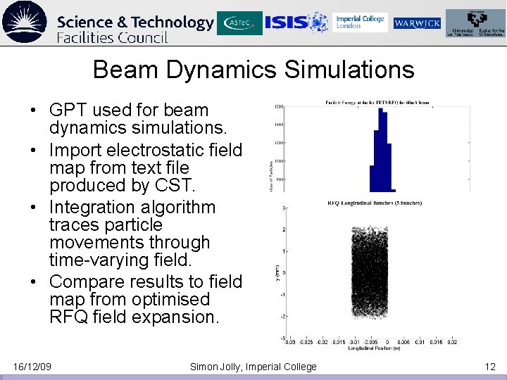
Beam Dynamics Simulations • GPT used for beam dynamics simulations. • Import electrostatic field map from text file produced by CST. • Integration algorithm traces particle movements through time-varying field. • Compare results to field map from optimised RFQ field expansion. 16/12/09 Simon Jolly, Imperial College 12
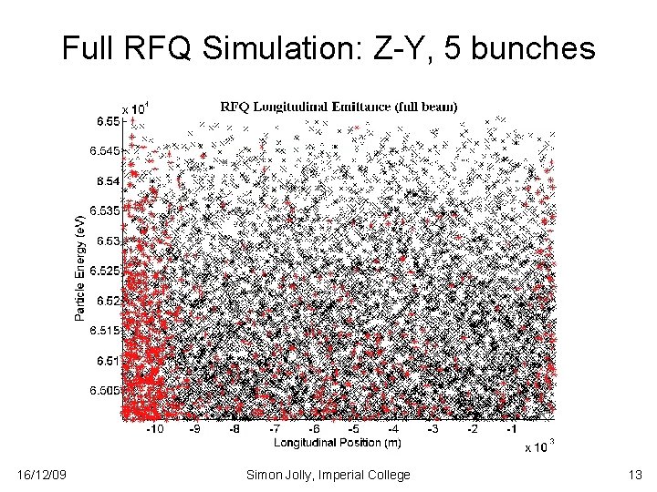
Full RFQ Simulation: Z-Y, 5 bunches 16/12/09 Simon Jolly, Imperial College 13
Full RFQ Simulation: Z-E, full beam 16/12/09 Simon Jolly, Imperial College 14
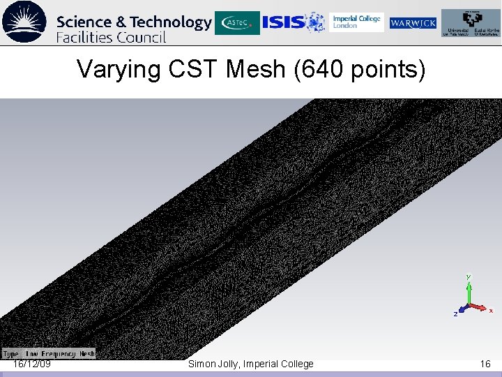
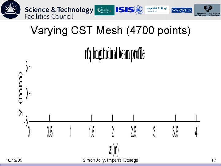
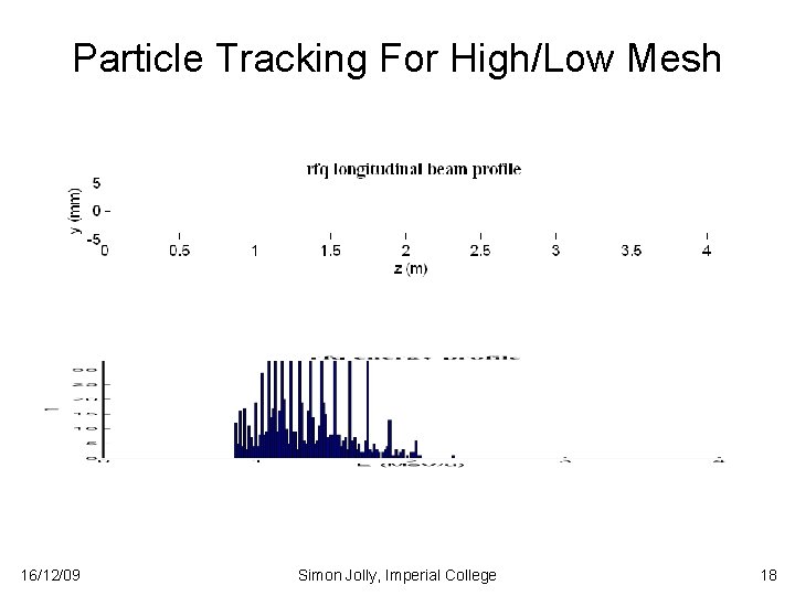
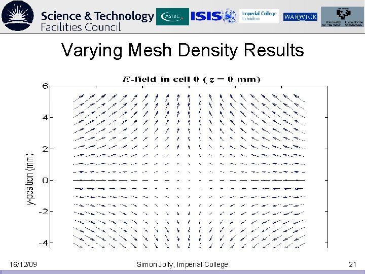
CST Mesh Density • A lot of effort on optimising meshing in CST. • Need a field map that gives transmission results similar to RFQSIM. • Important to quantify whether we can model Electrostatic field of vanes with enough accuracy in CST to measure beam dynamics. • Non-trivial: modelling 30 mm x 4 m volume with micron accuracy. • Changes in beam dynamics MUST be unaffected by coarseness of CST field meshing so we can compare to optimised field. 16/12/09 Simon Jolly, Imperial College 15
Varying CST Mesh (640 points) 16/12/09 Simon Jolly, Imperial College 16
Varying CST Mesh (4700 points) 16/12/09 Simon Jolly, Imperial College 17
Particle Tracking For High/Low Mesh 16/12/09 Simon Jolly, Imperial College 18
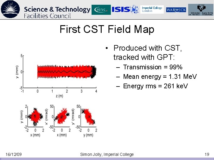
First CST Field Map • Produced with CST, tracked with GPT: – Transmission = 99% – Mean energy = 1. 31 Me. V – Energy rms = 261 ke. V 16/12/09 Simon Jolly, Imperial College 19
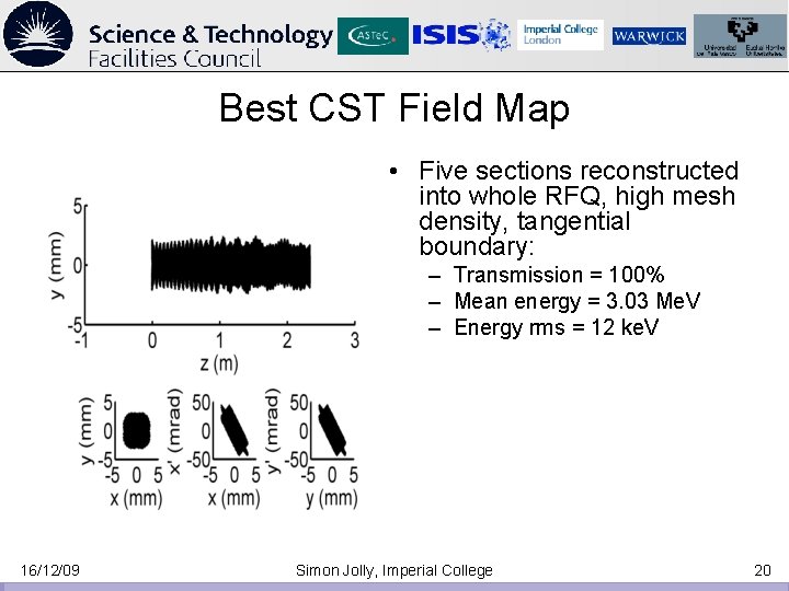
Best CST Field Map • Five sections reconstructed into whole RFQ, high mesh density, tangential boundary: – Transmission = 100% – Mean energy = 3. 03 Me. V – Energy rms = 12 ke. V 16/12/09 Simon Jolly, Imperial College 20
Varying Mesh Density Results 16/12/09 Simon Jolly, Imperial College 21
Transverse Field Map Comparison 16/12/09 Simon Jolly, Imperial College 22
Transverse Field Map Comparison 16/12/09 Simon Jolly, Imperial College 23
Conclusions • CAD modelling process now pretty mature: can model vane, rod and “vod” with parameter adjustment on-the-fly (everything except no. of cells). • Models import into CST and output to GPT: beam dynamics simulations well understood. • Need to ensure we’re not re-inventing the wheel: RFQ’s have been designed before without this process. • Next steps: – Output CAD model to Comsol, repeat process from CST to produce more easily adaptable field map (tighter integration with Inventor and Matlab). – Compare CST coarse, fine, Comsol and RFQSIM field maps point-by-point to determine whether discrepancies are a result of poor field mapping or more accurate modelling of vane tips. • Need to ensure CAM systems will understand our CAD models so we can manufacture what we’re designing (this is the point…). 16/12/09 Simon Jolly, Imperial College 24