
RFID ACCESSING SYSTEM USING ARM PROCESSOR By G
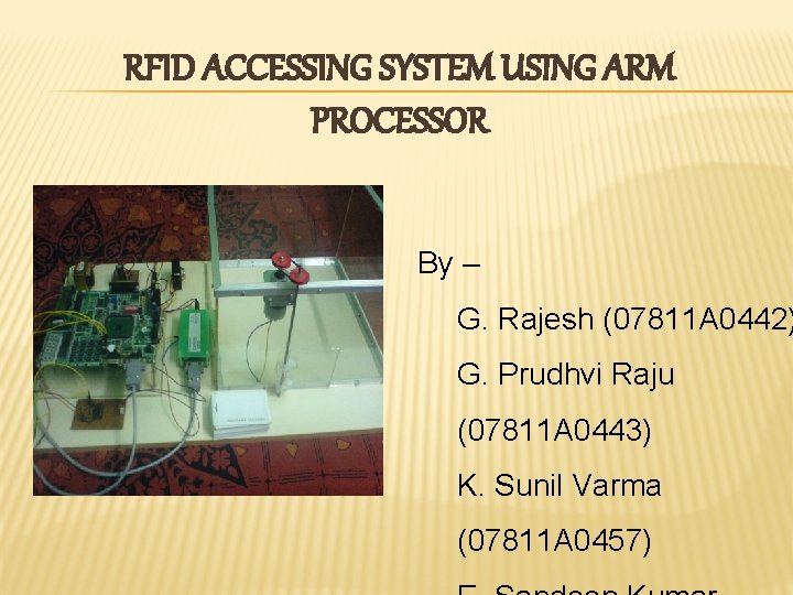
RFID ACCESSING SYSTEM USING ARM PROCESSOR By – G. Rajesh (07811 A 0442) G. Prudhvi Raju (07811 A 0443) K. Sunil Varma (07811 A 0457)
CONTENTS Ø Embedded systems Ø Microcontroller vs Microprocessor Ø Microcontrollers for Embedded Systems Ø ARM processor Ø Features of ARM processor Ø LPC 2119/LPC 2129 Ø Features of LPC 2119/LPC 2129 Ø Liquid Crystal Display (LCD) Ø RFID Reader Ø Power Supply ØAdvantages& Disadvantages Ø Conclusion Ø References
EMBEDDED SYSTEMS Ø We are living in the Embedded World. You are surrounded with many embedded products and your daily life largely depends on the proper functioning of these gadgets. Ø Embedded controllers carryout a specific work for which they are designed. Most of the time, engineers design these embedded controllers with a specific goal in mind. So these controllers cannot be used in any other place. Ø Theoretically, an embedded controller is a combination of a piece of microprocessor based hardware and the suitable software to undertake a specific task.
MICROCONTROLLER VS MICROPROCESSOR Ø Microprocessors contain no RAM, no ROM, and no I/O ports on the chip itself. For this reason, they are commonly referred to as general-purpose Microprocessors. Ø A Microcontroller has a CPU (a microprocessor) in addition to a fixed amount of RAM, ROM, I/O ports, and a timer all on a single chip. In other words, the processor, the RAM, ROM, I/O ports and the timer are all embedded together on one chip; therefore, the designer cannot add any external memory, I/O ports, or timer to it.
MICROCONTROLLERS FOR EMBEDDED SYSTEMS Ø An embedded system product uses a microprocessor (or Microcontroller) to do one task only. Ø In an Embedded system, there is only one application software that is typically burned into ROM Ø Each one of the output peripherals has a Microcontroller inside it that performs only one task. Ø For example, inside every mouse there is a Microcontroller to perform the task of finding the mouse position and sending it to the PC.
ARM PROCESSOR Ø The ARM processor core is a key component of many successful 32 -bit embedded systems. Ø ARM cores are widely used in mobile phones, handheld organizers, and a multitude of other everyday portable consumer devices. Ø Over one billion ARM processors had been shipped worldwide.
FEATURES OF ARM PROCESSOR Ø The ARM processor, like all RISC processors, uses a loadstore architecture. This means it has two instruction types for transferring data in and out of the processor. Ø Since the ARM core is a 32 -bit processor, most instructions treat the registers as holding signed or unsigned 32 -bit values. Ø The ARM core uses the cpsr to monitor and control internal operations. The cpsr is a dedicated 32 -bit register and resides in the register file. Ø The processor mode determines which registers are active and the access rights to the cpsr register itself.
Ø There are seven processor modes in total: six privileged modes (abort, fast interrupt request, supervisor, system, and undefined) and one nonprivileged mode (user). Ø The state of the core determines which instruction set is being executed. There are three instruction sets: ARM, Thumb, and Jazelle. Ø The ARM instruction set is only active when the processor is in ARM state. Ø To execute Java bytecodes, you require the Jazelle technology plus a specially modified version of the Java virtual machine Ø Interrupt masks are used to stop specific interrupt requests from interrupting the processor.
LPC 2119/LPC 2129 Ø The LPC 2119/LPC 2129 are based on a 16/32 bit ARM 7 TDMIS™ CPU with real-time emulation and embedded trace support, together with 128/256 kilobytes (k. B) of embedded high speed flash memory. Ø A 128 -bit wide memory interface and a unique accelerator architecture enable 32 -bit code execution at maximum clock rate. For critical code size applications, the alternative 16 -bit Thumb® Mode reduces code by more than 30 % with minimal performance penalty. Ø With a wide range of additional serial communications interfaces, they are also suited for communication gateways and protocol converters as well as many other general-purpose
FEATURES OF LPC 2119/LPC 2129 Ø 16/32 -bit ARM 7 TDMI-S microcontroller in a tiny LQFP 64 package. Ø 16 k. B on-chip Static RAM. Ø 128/256 k. B on-chip Flash Program Memory. 128 -bit wide interface/accelerator enables high speed 60 MHz operation. Ø In-System Programming (ISP) and In-Application Programming (IAP) via on-chip boot-loader software. Flash programming takes 1 ms per 512 byte line. Single sector or full chip erase takes 400 ms.
Ø Embedded ICE-RT interface enables breakpoints and watch points. Interrupt service routines can continue to execute while the foreground task is debugged with the onchip Real. Monitor™ software. Ø Two 32 -bit timers (with four capture and four compare channels), PWM unit (six outputs), Real Time Clock and Watchdog. Ø Up to forty-six 5 V tolerant general purpose I/O pins. Up to nine edge or level sensitive external interrupt pins available. Ø On-chip crystal oscillator with an operating range of 1 MHz to 30 MHz. Ø Dual power supply: • CPU operating voltage range of 1. 65 V to 1. 95 V (1. 8 V -0. 15 V). • I/O power supply range of 3. 0 V to 3. 6 V (3. 3 V - 10 %) with 5 V tolerant I/O pads.
LIQUID CRSYTAL DISPLAY Ø The liquid crystal display driver circuit consists of 16 common signal drivers and 40 segment signal drivers. Ø When the character font and number of lines are selected by a program, the required common signal drivers automatically output drive waveforms, while the other common signal drivers continue to output non-selection waveforms. Ø The display contains two internal byte-wide registers, one for commands (RS=0) and the second for characters to be displayed(RS=1). It also contains a user-programmed RAM area (the character RAM) that can be programmed to generate any desired character that can be formed using a dot matrix
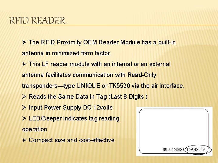
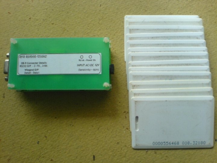
RFID READER Ø The RFID Proximity OEM Reader Module has a built-in antenna in minimized form factor. Ø This LF reader module with an internal or an external antenna facilitates communication with Read-Only transponders—type UNIQUE or TK 5530 via the air interface. Ø Reads the Same Data in Tag (Last 8 Digits ) Ø Input Power Supply DC 12 volts Ø LED/Beeper indicates tag reading operation Ø Compact size and cost-effective
POWER SUPPLY DESIGN ØVoltage Regulator is used to provide a constant voltage. Ø When the current in the regulator gets heated up so a heat sink is used which reduces the heat and saves the regulator from damage. Ø Two diodes are used as a rectifier to convert pulsating DC to constant DC.
ADVANTAGES Ø Provides a security system which needs no manpower to look after. Ø Very less maintenance cost. disadvantages Ø Anyone can enter the secured room with a lost RFID card. Ø High initial cost.

CONCLUSION Security is a primary concern in our day-today life. Everyone wants to be as much secure as possible. An access control for doors forms a vital link in a security chain. The RFID and Microcontroller based security system can be adopted at various applications and are very useful in providing an excellent security system.
REFERENCES Ø ‘The 8051 Microcontroller and Embedded Systems’ by Muhammad Ali Mazidi. Ø ‘ARM system developer Guide’ by Andrew N. Sloss. Ø www. atmel. com Ø www. analogicgroup. com Ø www. philips. com Ø www. nxp. com Ø www. gsmworld. com

- Slides: 20