
RFdriven H Ion Sources for High Power Accelerators
- Slides: 36
RF-driven H- Ion Sources for High Power Accelerators: Status and Challenges Baoxi Han, Robert Welton, and Martin Stockli Spallation Neutron Source Oak Ridge National Laboratory Oak Ridge, TN 37831, USA The 23 rd meeting of the International Collaboration on Advanced Neutron Sources (ICANS XXIII) Chattanooga, Tennessee, USA October 17, 2019 ORNL is managed by UT-Battelle for the US Department of Energy
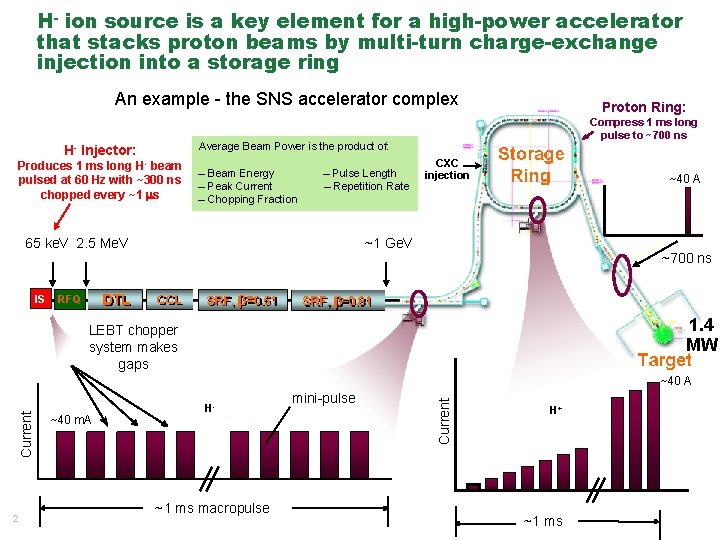
H- ion source is a key element for a high-power accelerator that stacks proton beams by multi-turn charge-exchange injection into a storage ring An example - the SNS accelerator complex Compress 1 ms long pulse to ~700 ns Average Beam Power is the product of: H- Injector: Produces 1 ms long H- beam pulsed at 60 Hz with ~300 ns chopped every ~1 s – Beam Energy – Peak Current – Chopping Fraction – Pulse Length – Repetition Rate 65 ke. V 2. 5 Me. V IS Proton Ring: CXC injection ~40 A ~1 Ge. V ~700 ns RFQ 1. 4 MW LEBT chopper system makes gaps Current ~40 m. A H- 1 ms macropulse 2 ~1 ms macropulse mini-pulse Current ~40 A 945 ns H+ 1 ms ~1 ms
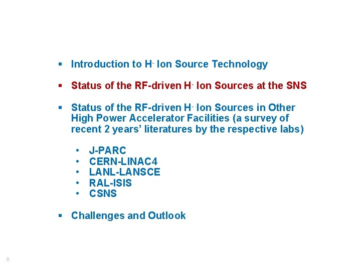
Outline of the talk § Introduction to H- Ion Source Technology § Status of the RF-driven H- Ion Sources at the SNS § Status of the RF-driven H- Ion Sources in Other High Power Accelerator Facilities (a survey of recent 2 years’ literatures by the respective labs) • • • J-PARC CERN-LINAC 4 LANL-LANSCE RAL-ISIS CSNS § Challenges and Outlook 3
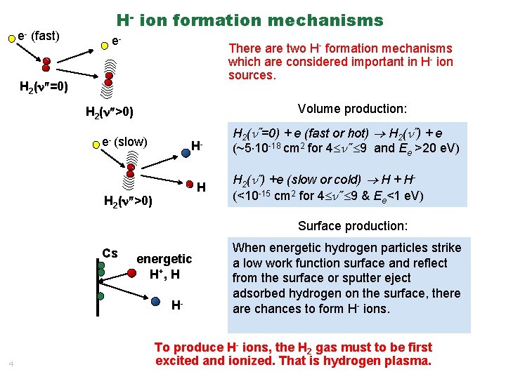
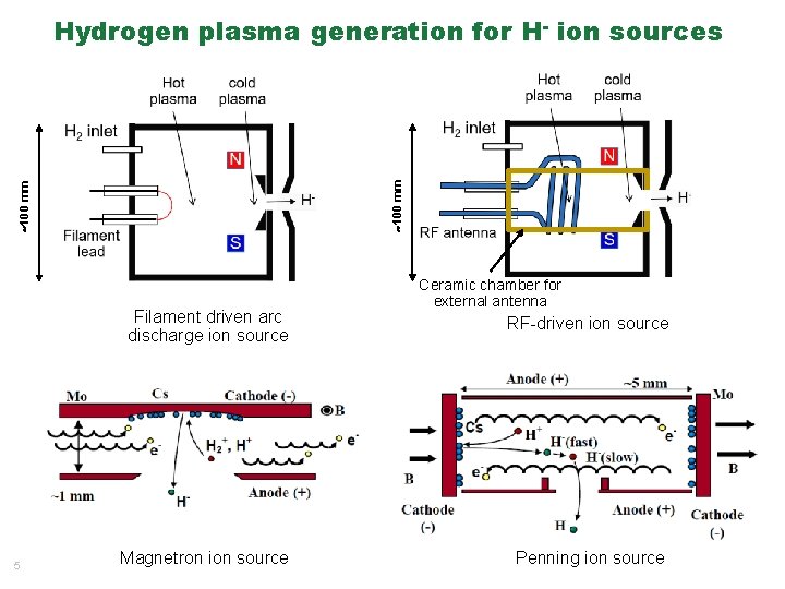
e- (fast) H- ion formation mechanisms e- There are two H- formation mechanisms which are considered important in H- ion sources. H 2(n =0) Volume production: H 2(n >0) e- (slow) HH H 2(n >0) H 2( =0) + e (fast or hot) H 2( ) + e (~5 10 -18 cm 2 for 4 9 and Ee >20 e. V) H 2( ) +e (slow or cold) H + H(<10 -15 cm 2 for 4 9 & Ee<1 e. V) Surface production: Cs energetic H+ , H H- 4 When energetic hydrogen particles strike a low work function surface and reflect from the surface or sputter eject adsorbed hydrogen on the surface, there are chances to form H- ions. To produce H- ions, the H 2 gas must to be first excited and ionized. That is hydrogen plasma.
100 mm Hydrogen plasma generation for H- ion sources Filament driven arc discharge ion source 5 Magnetron ion source Ceramic chamber for external antenna RF-driven ion source Penning ion source
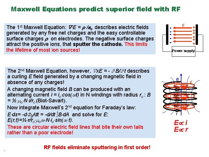
Maxwell Equations predict superior field with RF The 1 st Maxwell Equation: E = / o describes electric fields generated by any free net charges and the easy controllable surface charges on electrodes. The negative surface charges attract the positive ions, that sputter the cathode. This limits the lifetime of most ion sources! The 2 nd Maxwell Equation, however, x. E = - B/ t describes a curling E field generated by a changing magnetic field in absence of any charges! A changing magnetic field B can be produced with an alternating current i = io cos( t) in N windings with radius ro : B = ½ o N i/ro (Biot-Savart). Now integrate Maxwell’s 2 nd equation for Faraday’s law: E ds= -d B/dt = -d/dt ∫B d. A and solve for E: E(r, t)=¼ r/ro o N io sin( t). These are circular electric field lines that bite their own tails rather than a poor electrode! 6 RF fields eliminate sputtering in first order! E - + + + Power supply B i E r E
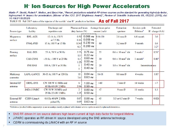
H- Ion Sources for High Power Accelerators Martin P. Stockli, Robert F. Welton, and Baoxi Han, “Record productions establish RF-driven sources as the standard for generating high-duty-factor, high-current H- beams for accelerators (Winner of the ICIS 2017 Brightness Award)”, Review of Scientific Instruments 89, 052202 (2018); doi: 10. 1063/1. 5025328 As of Fall 2017 0. 066 ms 0. 058 ms 0. 230 ms 0. 200 ms 0. 75 ms 0. 22 ms 0. 60 ms 0. 50 ms 0. 40 ms 0. 84 ms 0. 63 ms 1. 00 ms 0. 99 ms 0. 80 ms 0. 50 ms 0. 88 ms 0. 63 ms § SNS RF-driven H- ion source delivers high beam current at high duty-factor for longest lifetime. § J-PARC operates an RF-driven H- source developed using the SNS antenna technology. § CERN is commissioning its LINAC 4 with an RF H- source. 7
§ Introduction to H- Ion Source Technology § Status of the RF-driven H- Ion Sources at the SNS § Status of the RF-driven H- Ion Sources in Other High Power Accelerator Facilities (a survey of recent 2 years’ literatures by the respective labs) • • • J-PARC CERN-LINAC 4 LANL-LANSCE RAL-ISIS CSNS § Challenges and Outlook 8
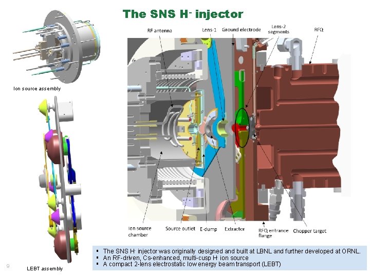
The SNS H- injector Ion source assembly 9 LEBT assembly § The SNS H- injector was originally designed and built at LBNL and further developed at ORNL. § An RF-driven, Cs-enhanced, multi-cusp H- ion source § A compact 2 -lens electrostatic low energy beam transport (LEBT)
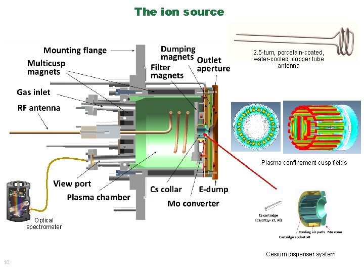
The ion source 2. 5 -turn, porcelain-coated, water-cooled, copper tube antenna Plasma confinement cusp fields Optical spectrometer Cesium dispenser system 10
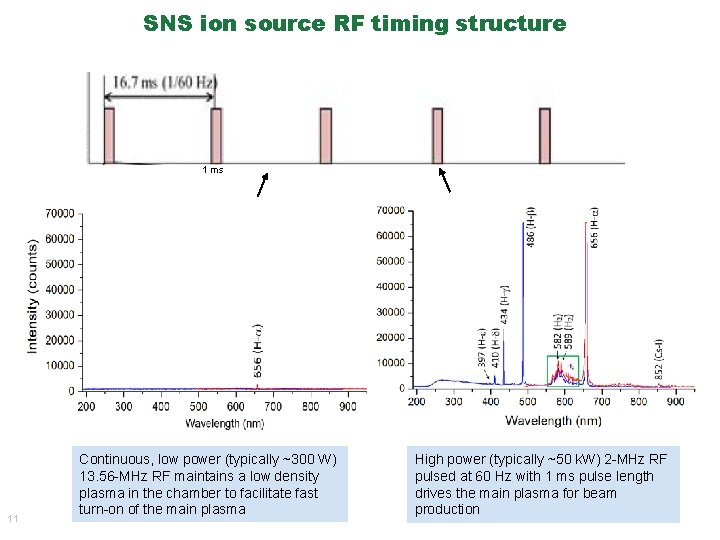
SNS ion source RF timing structure 1 ms 11 Continuous, low power (typically ~300 W) 13. 56 -MHz RF maintains a low density plasma in the chamber to facilitate fast turn-on of the main plasma High power (typically ~50 k. W) 2 -MHz RF pulsed at 60 Hz with 1 ms pulse length drives the main plasma for beam production
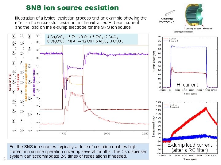
SNS ion source cesiation Illustration of a typical cesiation process and an example showing the effects of a successful cesiation on the extracted H- beam current and the load on the e-dump electrode for the SNS ion source 4 Cs 2 Cr. O 4 + 5 Zr 8 Cs + 5 Zr. O 2+2 Cr 2 O 3 6 Cs 2 Cr. O 4 + 10 Al 12 Cs + 5 Al 2 O 3+3 Cr 2 O 3 H- current 12 For the SNS ion sources, typically a dose of cesiation enables high current ion source operation covering several months. The Cs dispenser system can accommodate 2 -3 times of recesiations if needed. E-dump load current (after a RC filter)
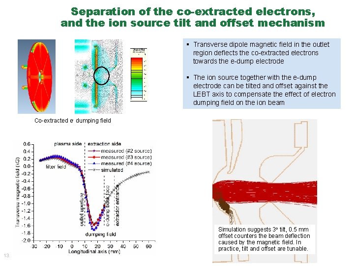
Separation of the co-extracted electrons, and the ion source tilt and offset mechanism T § Transverse dipole magnetic field in the outlet region deflects the co-extracted electrons towards the e-dump electrode § The ion source together with the e-dump electrode can be tilted and offset against the LEBT axis to compensate the effect of electron dumping field on the ion beam Co-extracted e- dumping field Simulation suggests 3 tilt, 0. 5 mm offset counters the beam deflection caused by the magnetic field. In practice, tilt and offset are tunable. 13
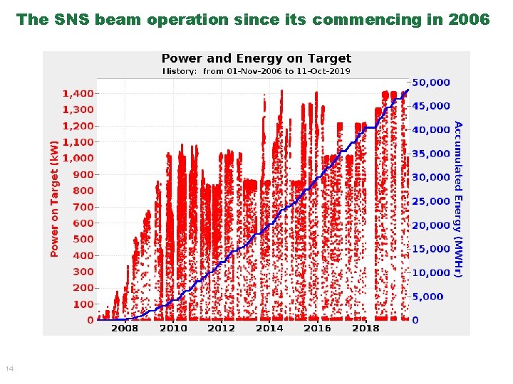
The SNS beam operation since its commencing in 2006 14
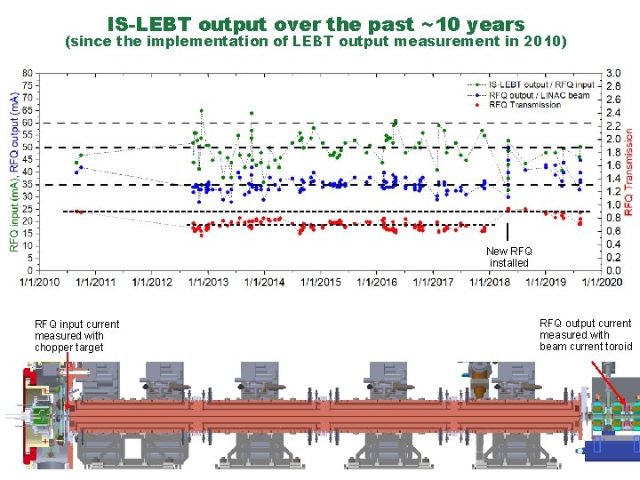
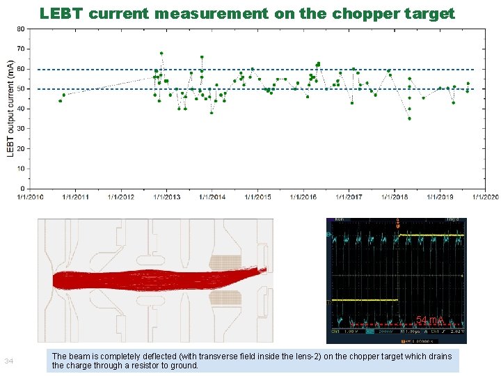
IS-LEBT output over the past ~10 years (since the implementation of LEBT output measurement in 2010) New RFQ installed RFQ input current measured with chopper target 15 RFQ output current measured with beam current toroid
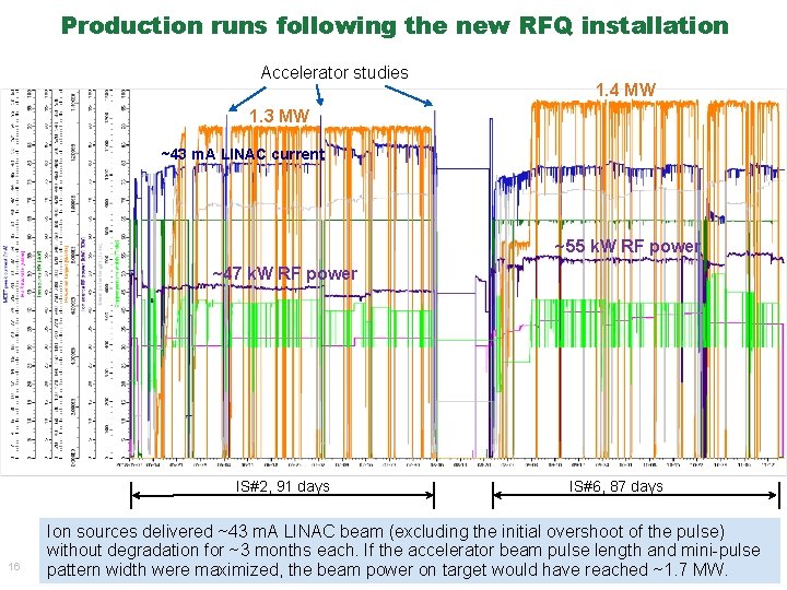
Production runs following the new RFQ installation Accelerator studies 1. 4 MW 1. 3 MW ~43 m. A LINAC current ~55 k. W RF power ~47 k. W RF power IS#2, 91 days 16 IS#6, 87 days Ion sources delivered ~43 m. A LINAC beam (excluding the initial overshoot of the pulse) without degradation for ~3 months each. If the accelerator beam pulse length and mini-pulse pattern width were maximized, the beam power on target would have reached ~1. 7 MW.
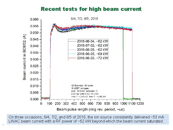
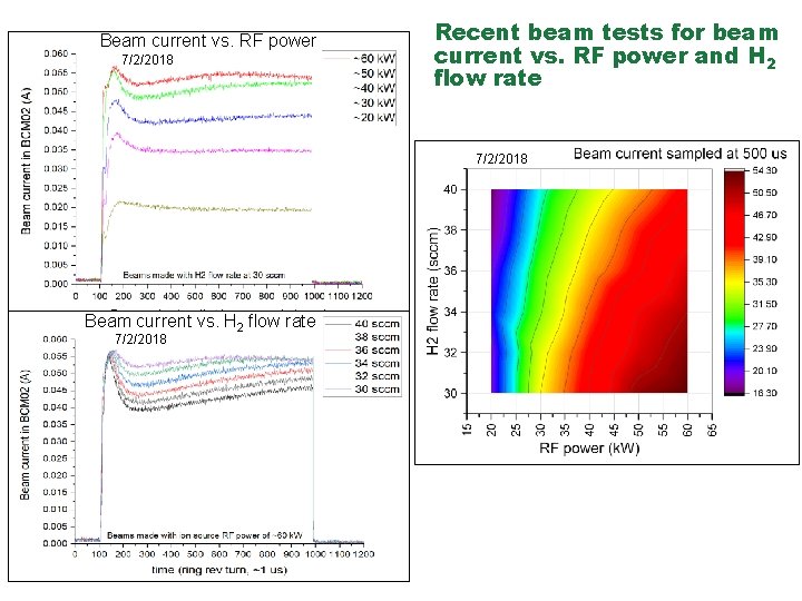
Recent tests for high beam current 6/4, 7/2, 8/5, 2018 On three occasions, 6/4, 7/2, and 8/5 of 2018, the ion source consistently delivered ~53 m. A LINAC beam current with a RF power of ~62 k. W beyond which the beam current saturated. 17
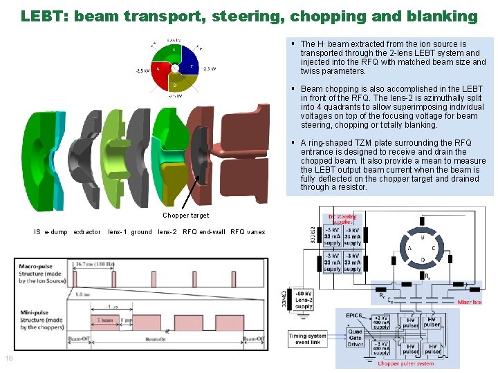
LEBT: beam transport, steering, chopping and blanking § The H- beam extracted from the ion source is transported through the 2 -lens LEBT system and injected into the RFQ with matched beam size and twiss parameters. § Beam chopping is also accomplished in the LEBT in front of the RFQ. The lens-2 is azimuthally split into 4 quadrants to allow superimposing individual voltages on top of the focusing voltage for beam steering, chopping or totally blanking. § A ring-shaped TZM plate surrounding the RFQ entrance is designed to receive and drain the chopped beam. It also provide a mean to measure the LEBT output beam current when the beam is fully deflected on the chopper target and drained through a resistor. Chopper target IS e-dump extractor 18 lens-1 ground lens-2 RFQ end-wall RFQ vanes
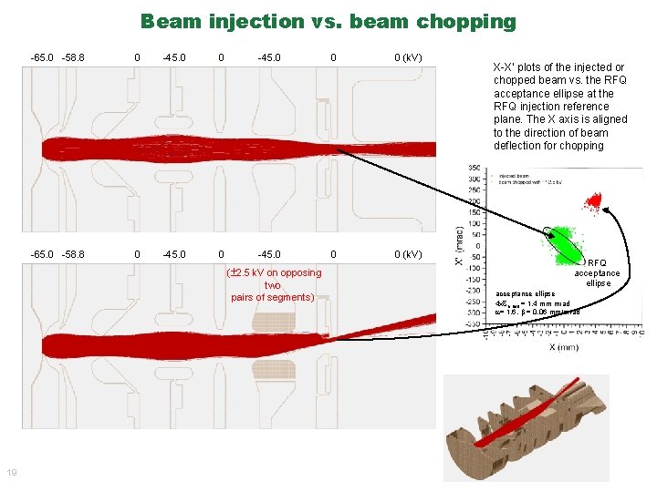
Beam injection vs. beam chopping -65. 0 -58. 8 0 -45. 0 0 0 (k. V) ( 2. 5 k. V on opposing two pairs of segments) X-X’ plots of the injected or chopped beam vs. the RFQ acceptance ellipse at the RFQ injection reference plane. The X axis is aligned to the direction of beam deflection for chopping RFQ acceptance ellipse 4 x n, rms = 1. 4 mm mrad = 1. 6, = 0. 06 mm/mrad X-X’ (or Y-Y’) plot of the injected beam vs. the RFQ acceptance ellipse 19
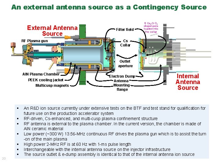
An external antenna source as a Contingency Source External Antenna Source RF Plasma gun Filter field 8 Cs 2 Cr. O 4 dispensers loaded into the collar Cs Collar Outlet aperture Al. N Plasma Chamber PEEK cooling jacket Multicusp magnets § § 20 § § § Electron Dump Antenna Mounting flange Internal Antenna Source An R&D ion source currently under extensive tests on the BTF and test stand for qualification for future use on the production accelerator system RF-driven, Cs-enhanced, and multi-cusp plasma confinement structure RF antenna is external to the plasma chamber. In the current version, the chamber is made of Al. N ceramic material Low power (~300 W) 13. 56 -MHz continuous RF drives the plasma gun which is to assist the turn -on of the main plasma High power 2 -MHz RF is at 60 Hz with 1 -ms pulse length Interchangeable with the internal antenna source on the injector infrastructure The source outlet & e-dump assembly is identical to that of the internal antenna ion source
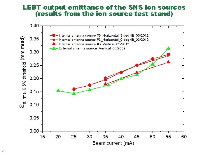
LEBT output emittance of the SNS ion sources (results from the ion source test stand) 21
§ Introduction to H- Ion Source Technology § Status of the RF-driven H- Ion Sources at the SNS § Status of the RF-driven H- Ion Sources in Other High Power Accelerator Facilities (a survey of recent 2 years’ literatures by the respective labs) • • • J-PARC CERN-LINAC 4 LANL-LANSCE RAL-ISIS CSNS § Challenges and Outlook 22
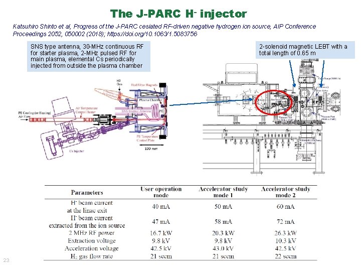
The J-PARC H- injector Katsuhiro Shinto et al, Progress of the J-PARC cesiated RF-driven negative hydrogen ion source, AIP Conference Proceedings 2052, 050002 (2018); https: //doi. org/10. 1063/1. 5083756 SNS type antenna, 30 -MHz continuous RF for starter plasma, 2 -MHz pulsed RF for main plasma, elemental Cs periodically injected from outside the plasma chamber 23 2 -solenoid magnetic LEBT with a total length of 0. 65 m
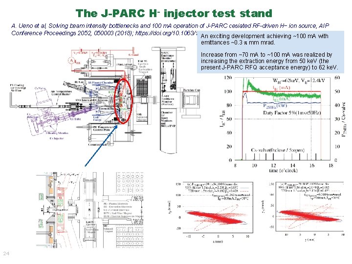
The J-PARC H- injector test stand A. Ueno et al, Solving beam intensity bottlenecks and 100 m. A operation of J-PARC cesiated RF-driven H− ion source, AIP Conference Proceedings 2052, 050003 (2018); https: //doi. org/10. 1063/1. 5083757 An exciting development achieving ~100 m. A with emittances ~0. 3 mm mrad. Increase from ~70 m. A to ~100 m. A was realized by increasing the extraction energy from 50 ke. V (the present J-PARC RFQ acceptance energy) to 62 ke. V. 24
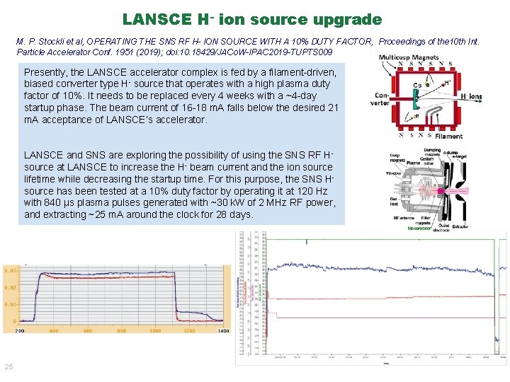
LANSCE H- ion source upgrade M. P. Stockli et al, OPERATING THE SNS RF H- ION SOURCE WITH A 10% DUTY FACTOR, Proceedings of the 10 th Int. Particle Accelerator Conf. 1951 (2019); doi: 10. 18429/JACo. W-IPAC 2019 -TUPTS 009 Presently, the LANSCE accelerator complex is fed by a filament-driven, biased converter type H- source that operates with a high plasma duty factor of 10%. It needs to be replaced every 4 weeks with a ~4 -day startup phase. The beam current of 16 -18 m. A falls below the desired 21 m. A acceptance of LANSCE’s accelerator. LANSCE and SNS are exploring the possibility of using the SNS RF Hsource at LANSCE to increase the H- beam current and the ion source lifetime while decreasing the startup time. For this purpose, the SNS Hsource has been tested at a 10% duty factor by operating it at 120 Hz with 840 μs plasma pulses generated with ~30 k. W of 2 MHz RF power, and extracting ~25 m. A around the clock for 28 days. 25
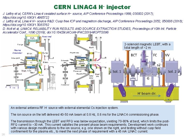
CERN LINAC 4 H- injector J. Lettry et al, CERN’s Linac 4 cesiated surface H− source, AIP Conference Proceedings 1869, 030002 (2017); https: //doi. org/10. 1063/1. 4995722 J. Lettry et al, Linac 4 H− source R&D: Cusp free ICP and magnetron discharge, AIP Conference Proceedings 2052, 050008 (2018); https: //doi. org/10. 1063/1. 5083762 D. Noll et al, LINAC 4: RELIABILITY RUN RESULTS AND SOURCE EXTRACTION STUDIES, Proceedings of 10 th Int. Particle Accelerator Conf. , 1090 (2019); doi: 10. 18429/JACo. W-IPAC 2019 -MOPTS 096 2 -solenoid magnetic LEBT, with a total length of ~2 m An external antenna RF H- source with external elemental Cs injection system. The ion source on the left delivered 40 -50 m. A beam at 0. 8 Hz, 0. 6 ms for the LINAC 4 commissioning phase. 26 The transmission through the LEBT and RFQ was below expectation, yielding 70 -80% at best, which limits the post. RFQ current to ~30 m. A. This current satisfies the present phase beam requirements. Development work continues with various design modifications to the ion source, e. g. one shown on the right, and testing without cusp field confinement for the plasma etc. , to meet the next phase of requirement with a 45 m. A LINAC current.
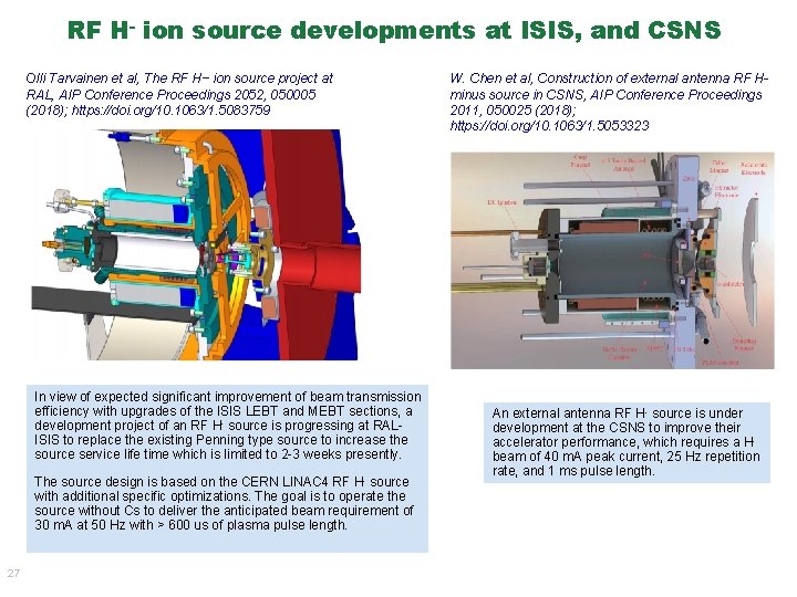
RF H- ion source developments at ISIS, and CSNS Olli Tarvainen et al, The RF H− ion source project at RAL, AIP Conference Proceedings 2052, 050005 (2018); https: //doi. org/10. 1063/1. 5083759 In view of expected significant improvement of beam transmission efficiency with upgrades of the ISIS LEBT and MEBT sections, a development project of an RF H- source is progressing at RALISIS to replace the existing Penning type source to increase the source service life time which is limited to 2 -3 weeks presently. The source design is based on the CERN LINAC 4 RF H- source with additional specific optimizations. The goal is to operate the source without Cs to deliver the anticipated beam requirement of 30 m. A at 50 Hz with > 600 us of plasma pulse length. 27 W. Chen et al, Construction of external antenna RF Hminus source in CSNS, AIP Conference Proceedings 2011, 050025 (2018); https: //doi. org/10. 1063/1. 5053323 An external antenna RF H- source is under development at the CSNS to improve their accelerator performance, which requires a Hbeam of 40 m. A peak current, 25 Hz repetition rate, and 1 ms pulse length.
§ Introduction to H- Ion Source Technology § Status of the RF-driven H- Ion Sources at the SNS § Status of the RF-driven H- Ion Sources in Other High Power Accelerator Facilities (a survey of recent 2 years’ literatures by the respective labs) • • • J-PARC CERN-LINAC 4 LANL-LANSCE RAL-ISIS CSNS § Challenges and Outlook 28
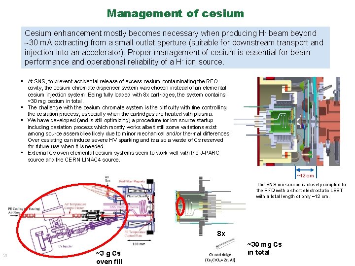
Management of cesium Cesium enhancement mostly becomes necessary when producing H- beam beyond 30 m. A extracting from a small outlet aperture (suitable for downstream transport and injection into an accelerator). Proper management of cesium is essential for beam performance and operational reliability of a H- ion source. • At SNS, to prevent accidental release of excess cesium contaminating the RFQ cavity, the cesium chromate dispenser system was chosen instead of an elemental cesium injection system. Being fully loaded with 8 x cartridges, the system contains ~30 mg cesium in total. • The challenge with the cesium chromate system is the difficulty with fine controlling the cesiation process, especially when the cartridges are heated with plasma. • We have developed (and is still optimizing) a procedure for ion source startup including cesiation process which mostly works albeit still some variations exist among source assemblies likely due to minor mechanical and/or thermal differences. Over cesiating can induce severe HV sparking and is also a waste of Cs reserved for future use when it is needed. • External Cs oven elemental cesium systems seem to work well with the J-PARC source and the CERN LINAC 4 source. ~12 cm The SNS ion source is closely coupled to the RFQ with a short electrostatic LEBT with a total length of only ~12 cm. 8 x 29 ~3 g Cs oven fill ~30 mg Cs in total
Handling of co-extracted electrons Handling of the co-extracted electrons is a critical issue for almost every high power H - ion sources. • Co-extracted electrons can cause problems if not handled properly, such as thermal damage to the e-dump electrode, and/or loading down the e-dump power supply in the cases when the source is operated uncesiated or if the Cs coverage becomes off optimal. • Under certain failure conditions, for example when the e-dump power supply trips, electrons can escape the dump and reach higher energy to cause elevated x-ray hazard. Growing emittance with higher current Producing higher current typically accompanies with higher emittances. Transporting and injecting the beam with high efficiency to the next acceleration structure, typically an RFQ accelerator, and beyond is challenging. • Beam emittance of the SNS ion source is <0. 3 mm mrad for 50 -60 m. A current and appears to be within the RFQ acceptance yielding ~90% transmission. • The J-PARC R&D effort of ~100 m. A with ~0. 3 mm mrad emittance is an encouraging result. • CERN RF H- source seems to yield larger emittance that likely causing the reduced transmission through the LEBT and RFQ. 30
Summary § The H- injector on the SNS accelerator typically delivers ~50 -60 m. A to the RFQ at 6% duty-factor (60 Hz, 1 ms) for several months in accordance with the facility run schedule. With a new RFQ installed, the beam transmission has improved from ~70% to ~90%, and the ion source maintains a significant margin for the present operational beam power at 1. 4 MW and is promising to meet the requirement of the future power upgrade plan with routine LINAC beam current of ~50 m. A. § The J-PARC H- injector delivers 40 m. A of LINAC current at 1. 5% duty-factor (25 Hz, 0. 6 ms) with a comfortable margin. The test stand R&D work producing ~100 m. A with ~0. 3 mm mrad emittance is very encouraging for the accelerator community. § The CERN LINAC 4 RF H- ion source delivers 40 -50 m. A beam to the LEBT. The team is working to improve the beam transmission through the LEBT and RFQ, which is currently limited at 70 -80%. § LANSCE is working toward adapting the SNS ion source in the near future. § ISIS and CSNS are designing RF H- ion sources for their accelerator performance improvements. § Management of cesium, handling of co-extracted electrons and high efficiency transmission of high current beam through the LEBT and RFQ remains as challenges. Thank you for your attention! 31
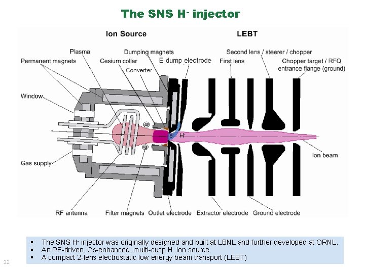
The SNS H- injector e- H- 32 § § § The SNS H- injector was originally designed and built at LBNL and further developed at ORNL. An RF-driven, Cs-enhanced, multi-cusp H- ion source A compact 2 -lens electrostatic low energy beam transport (LEBT)
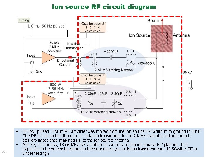
Ion source RF circuit diagram § § 33 80 -k. W, pulsed, 2 -MHz RF amplifier was moved from the ion source HV platform to ground in 2010. The RF is transmitted through an isolation transformer to the 2 -MHz matching network which delivers impedance matched RF to the ion source antenna. 600 -W, continuous, 13. 56 -MHz RF amplifier is currently on the ion source HV platform. It is expected to be moved to ground in the near future (an isolation transformer for 13. 56 -MHz RF is under testing. )
LEBT current measurement on the chopper target 54 m. A 34 The beam is completely deflected (with transverse field inside the lens-2) on the chopper target which drains the charge through a resistor to ground.
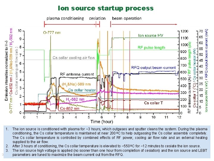
Ion source startup process 1. The ion source is conditioned with plasma for ~3 hours, which outgases and sputter cleans the system. During the plasma conditioning, the Cs collar temperature is maintained at near 200 0 C to help outgassing the Cs collar assembly completely. The Cs collar temperature is controlled by combined effects of RF power, cooling air flow rate and an external heating supplied to the air flow. 2. After 3 hours of conditioning, the Cs collar temperature is elevated to ~550 0 C for ~12 minutes to cesiate the ion source. 3. The ion source high voltage is applied (no sooner than one hour from completion of cesiation) and the ion source and LEBT 35 parameters are tuned to maximize the beam current out from the RFQ.
Beam current vs. RF power 7/2/2018 Recent beam tests for beam current vs. RF power and H 2 flow rate 7/2/2018 Beam current vs. H 2 flow rate 7/2/2018 36