
rfc 2547 bis VPN Alvaro Retana aretanacisco com
rfc 2547 bis VPN Alvaro Retana aretana@cisco. com MPLS QOS 10/00 © 2000, Cisco Systems, Inc. 1
MPLS/BGP VPNs • Goals • MPLS/BGP VPN Features • Implementation • Conclusions MPLS VPNs © 2000, Cisco Systems, Inc. 2
Objectives Provide a solution that enables Service Providers to offer VPN service that: scales to large number of customers (100, 000 1, 000 VPNs) most of customers with little/no IP routing expertise supports diverse customer population including large VPNs (100 s - 1000 s sites per VPN) value added service low cost service MPLS VPNs © 2000, Cisco Systems, Inc. 3
What is a VPN ? • VPN is a set of sites which are allowed to communicate with each other • VPN is defined by a set of administrative policies determine both connectivity and Qo. S among sites policies established by VPN customers policies could be implemented completely by VPN Service Providers using BGP/MPLS VPN mechanisms MPLS VPNs © 2000, Cisco Systems, Inc. 4
What is a VPN (cont. )? • Flexible inter-site connectivity ranging from complete mesh to hub-and-spoke • Sites may be either within the same or in different organizations VPN can be either Intranet or Extranet • Site may be in more than one VPNs may overlap • Not all sites have to be connected to the same service provider VPN can span multiple providers MPLS VPNs © 2000, Cisco Systems, Inc. 5
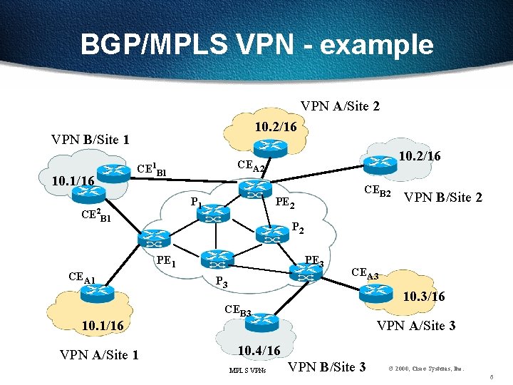
BGP/MPLS VPN - example VPN A/Site 2 10. 2/16 VPN B/Site 1 10. 1/16 CE B 1 P 1 CE 2 B 1 10. 2/16 CEA 2 1 PE 2 10. 1/16 VPN A/Site 1 VPN B/Site 2 PE 1 CEA 1 CEB 2 PE 3 P 3 CEA 3 10. 3/16 CEB 3 VPN A/Site 3 10. 4/16 MPLS VPNs VPN B/Site 3 © 2000, Cisco Systems, Inc. 6
BGP/MPLS VPN key components: (1) Constrained distribution of routing information + multiple forwarding tables (2) Address extension (3) MPLS VPNs © 2000, Cisco Systems, Inc. 7
Constrained Distribution of Routing Information • Provides control over connectivity among sites flow of data traffic (connectivity) is determined by flow (distribution) of routing information MPLS VPNs © 2000, Cisco Systems, Inc. 8
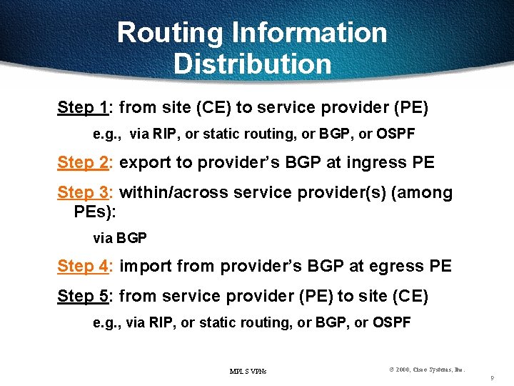
Routing Information Distribution Step 1: from site (CE) to service provider (PE) e. g. , via RIP, or static routing, or BGP, or OSPF Step 2: export to provider’s BGP at ingress PE Step 3: within/across service provider(s) (among PEs): via BGP Step 4: import from provider’s BGP at egress PE Step 5: from service provider (PE) to site (CE) e. g. , via RIP, or static routing, or BGP, or OSPF MPLS VPNs © 2000, Cisco Systems, Inc. 9
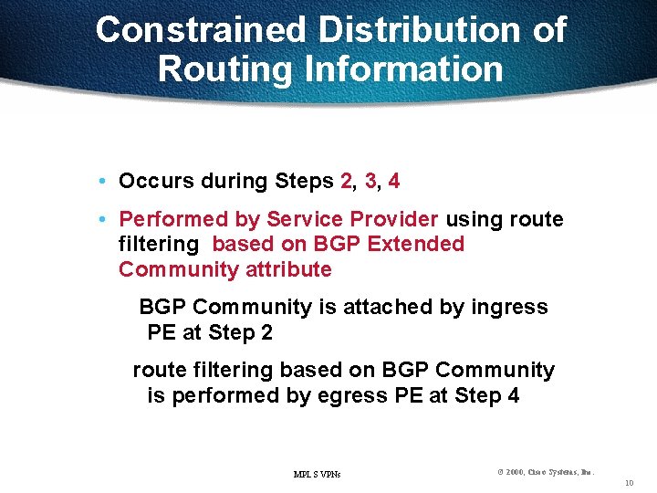
Constrained Distribution of Routing Information • Occurs during Steps 2, 3, 4 • Performed by Service Provider using route filtering based on BGP Extended Community attribute BGP Community is attached by ingress PE at Step 2 route filtering based on BGP Community is performed by egress PE at Step 4 MPLS VPNs © 2000, Cisco Systems, Inc. 10
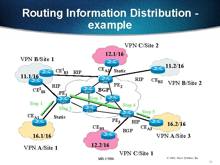
Routing Information Distribution example VPN C/Site 2 12. 1/16 VPN B/Site 1 1 11. 1/16 CE 2 B 1 CE B 1 RIP RIP PE 1 Step 1 CEA 1 11. 2/16 CEA 2 Static BGP PE 2 VPN B/Site 2 Step 3 Step 4 Step 2 Step 5 Static PE 3 CEB 3 16. 1/16 VPN A/Site 1 CEB 2 RIP BGP CEA 3 16. 2/16 VPN A/Site 3 12. 2/16 VPN C/Site 1 MPLS VPNs © 2000, Cisco Systems, Inc. 11
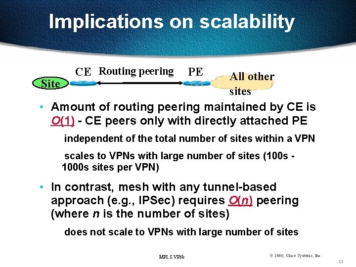
Implications on scalability CE Routing peering PE All other Site sites • Amount of routing peering maintained by CE is O(1) - CE peers only with directly attached PE independent of the total number of sites within a VPN scales to VPNs with large number of sites (100 s 1000 s sites per VPN) • In contrast, mesh with any tunnel-based approach (e. g. , IPSec) requires O(n) peering (where n is the number of sites) does not scale to VPNs with large number of sites MPLS VPNs © 2000, Cisco Systems, Inc. 12
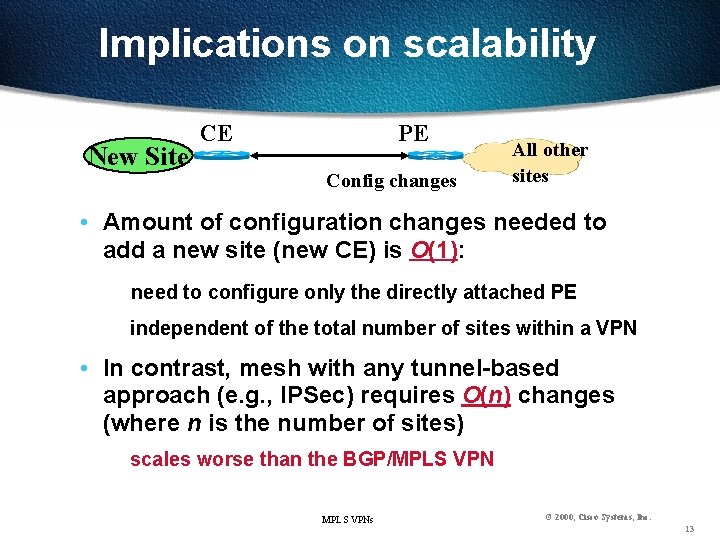
Implications on scalability New Site CE PE Config changes All other sites • Amount of configuration changes needed to add a new site (new CE) is O(1): need to configure only the directly attached PE independent of the total number of sites within a VPN • In contrast, mesh with any tunnel-based approach (e. g. , IPSec) requires O(n) changes (where n is the number of sites) scales worse than the BGP/MPLS VPNs © 2000, Cisco Systems, Inc. 13
Multiple Forwarding Tables • How to constrain distribution of routing information at PE that has sites from multiple (disjoint) VPNs attached to it ? single Forwarding Table on PE doesn’t allow per VPN segregation of routing information MPLS VPNs © 2000, Cisco Systems, Inc. 14
Multiple Forwarding Tables (cont. ) • PE maintains multiple Forwarding Tables one per set of directly attached sites with common VPN membership e. g. , one for all the directly attached sites that are in just one particular VPN • Enables (in conjunction with route filtering) per VPN segregation of routing information on PE MPLS VPNs © 2000, Cisco Systems, Inc. 15
Multiple Forwarding Tables (cont. ) • Each Forwarding Table is populated from: (a) routes received from directly connected CE(s) of the site(s) associated with the Forwarding Table (b) routes receives from other PEs (via BGP) restricted to only the routes of the VPN(s) the site(s) is in via route filtering based on BGP Extended Community Attribute MPLS VPNs © 2000, Cisco Systems, Inc. 16
Multiple Forwarding Tables (cont. ) • Each customer port on PE is associated with a particular Forwarding Table via configuration management (at provisioning time) • Provides PE with per site (per VPN) forwarding information for packets received from CEs • Ports on PE could be “logical” e. g. , VLAN, FR, ATM, L 2 F, etc. . . MPLS VPNs © 2000, Cisco Systems, Inc. 17
MPLS VPN example: full mesh • One BGP Community Cclosed • At PE with directly attached site: exports all site’s routes into provider’s BGP with Community Cclosed imports into the forwarding table associated with the VPN (site) only routes with Cclosed • Could also be realized with more than one BGP Community useful when VPN spans multiple providers MPLS VPNs © 2000, Cisco Systems, Inc. 18
Address Extension • How to support VPNs without imposing constraints on address allocation/management within VPNs (e. g. , allowing private address space [RFC 1918]) ? constrained distribution of routing information uses BGP is designed with the assumption that addresses are unique MPLS VPNs © 2000, Cisco Systems, Inc. 19
VPN-IP Addresses • New address family: VPN-IP addresses VPN-IP address = Route Distinguisher (RD) + IP address RD = Type + Provider’s Autonomous System Number + Assigned Number No two VPNs have the same RD convert non-unique IP addresses into unique VPN-IP addresses • Reachability information for VPN-IP addresses is carried via multiprotocol extensions to BGP-4 MPLS VPNs © 2000, Cisco Systems, Inc. 20
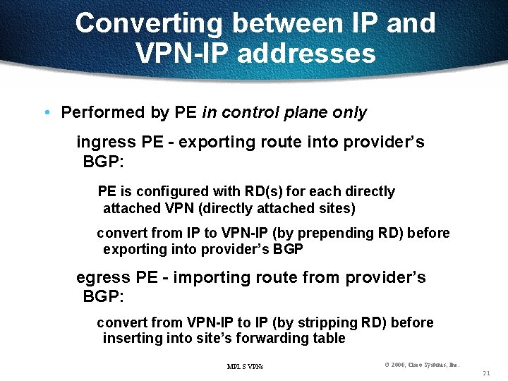
Converting between IP and VPN-IP addresses • Performed by PE in control plane only ingress PE - exporting route into provider’s BGP: PE is configured with RD(s) for each directly attached VPN (directly attached sites) convert from IP to VPN-IP (by prepending RD) before exporting into provider’s BGP egress PE - importing route from provider’s BGP: convert from VPN-IP to IP (by stripping RD) before inserting into site’s forwarding table MPLS VPNs © 2000, Cisco Systems, Inc. 21
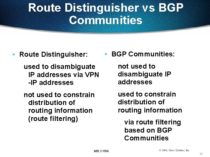
Route Distinguisher vs BGP Communities • BGP Communities: • Route Distinguisher: used to disambiguate IP addresses via VPN -IP addresses not used to disambiguate IP addresses not used to constrain distribution of routing information (route filtering) used to constrain distribution of routing information MPLS VPNs via route filtering based on BGP Communities © 2000, Cisco Systems, Inc. 22
MPLS • Given that BGP operates in term of VPN- IP addresses, how to forward IP packets within Service Provider(s) along the routes computed by BGP ? IP header has no place to carry Route Distinguisher MPLS VPNs © 2000, Cisco Systems, Inc. 23
MPLS (cont. ) • Use MPLS forwarding MPLS decouples information used forwarding (label) from the information carried in the IP header • Label Switched Paths (labels) are bound to VPN-IP routes • Label Switched Paths are confined to VPN Service Provider(s) MPLS VPNs © 2000, Cisco Systems, Inc. 24
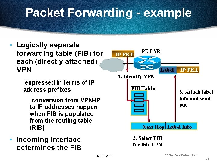
Packet Forwarding - example • Logically separate forwarding table (FIB) for each (directly attached) VPN expressed in terms of IP address prefixes IP PKT PE LSR Label 1. Identify VPN FIB Table conversion from VPN-IP to IP addresses happen when FIB is populated from the routing table (RIB) IP PKT 3. Attach label info and send out Next Hop Label Info 2. Select FIB for this VPN • Incoming interface determines the FIB MPLS VPNs © 2000, Cisco Systems, Inc. 25
Two-level label stack • VPN routing information is carried only among PE routers (using BGP) • BGP Next Hop provides coupling between external routes (VPN routes) and service provider internal route (IGP routes) route to Next Hop is an internal route • Top (first) level label is used forwarding from ingress PE to egress PE • Bottom (second) level is used forwarding at egress PE distributed via BGP (together with the VPN route) Þ P routers maintain only internal routes (routes to PE routers and other P routers), but no VPN MPLS VPNs routes © 2000, Cisco Systems, Inc. 26
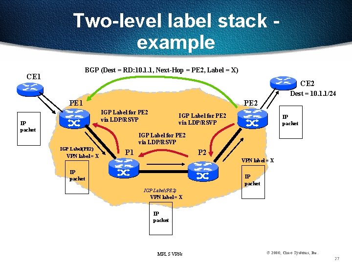
Two-level label stack example BGP (Dest = RD: 10. 1. 1, Next-Hop = PE 2, Label = X) CE 1 CE 2 Dest = 10. 1. 1/24 PE 1 PE 2 IGP Label for PE 2 via LDP/RSVP IP packet IGP Label for PE 2 via LDP/RSVP IGP Label(PE 2) VPN label = X P 1 P 2 VPN label = X IP packet IGP Label(PE 2) VPN label = X IP packet MPLS VPNs © 2000, Cisco Systems, Inc. 27
Scalability - “divide and conquer” (1) Two levels of labels to keep P routers free of all the VPN routing information (2) PE router has to maintain routes only for VPNs whose sites are directly connected to the PE router (3) Partition BGP Route Reflectors within the VPN Service Provider among VPNs served by the Provider Þ No single component within the system is required to maintain all routes for all the VPNs Þ Capacity of the system isn’t bounded by the capacity of an individual component MPLS VPNs © 2000, Cisco Systems, Inc. 28
BGP/MPLS VPN - Summary • Supports large scale VPN services • Increases value add by the VPN Service Provider • Decreases Service Provider’s cost of providing VPN services • Simplifies operations for VPN customers • Mechanisms are general enough to enable VPN Service Provider to support a wide range of VPN customers MPLS VPNs © 2000, Cisco Systems, Inc. 29
- Slides: 29