RF section Control section GPS TI CC 1101


 1. 03 mm 0. 5 mm 3. 55 mm")
- Slides: 13
RF section Control section GPS TI CC 1101 E Transceiver CPU LC 915 MHz 10 d. Bm Hybrid Mixer HMC 1056 Interface board splitter 8 GHz 0 d. Bm Kuhne Amplifier PA 600770 -2 3 -way splitter PE 42441 Output Section 8 GHz 30 d. Bm Antenna 1 7 GHz 10 d. Bm 8 GHz 6 d. Bm Df Df Df DAC DAC LO HMC 765 Antenna 2 Antenna 3 CPU Tegra TK 1 12 V USRP Ettus B 210 USB powered LO HMC 765 7 -9 GHz 15 V, 5. 5 V DAC MCP 4725 3. 3 V DAC buffer 1 A 12 V RF Switches Peregrine PE 42441 3. 3 V, TTL RF Power Amp Kuhne KUPA 600770 -2 12 V Total ~ 100 W 2 A (x 3)
GPS RF section Control section CPU TI CC 1101 E Transceiver 915 MHz -100 d. Bm Mixer WJ-12 LO HMC 765 High Gain Antenna 7 GHz 10 d. Bm Digital Recorder Low Gain Antenna Pointing Control CPU Tegra TK 1 12 V Digital Recorder Ettus B 210 USB powered LO HMC 765 7 -9 GHz 15 V, 5. 5 V DAC MCP 4725 5 V DAC buffer 1 A 12 V RF Switches RLC SR-2 -MININ 12 V, TTL 120 m. A (x 6) RF Power Amp Kuhne KUPA 600770 -2 12 V 2 A (x 3) Total ~ 100 W
Flight computer • • • NVIDIA Tegra TK 1 ARM processor 12 V DC USB 3. 0 for SDR USB 2. 0 for webcam Digital IO and RS 232 • SPI bus for LO • I 2 C bus for DAC • IO for RF switches • 13 x 4 cm • Status • In lab, software mostly in progress
General interface board Multiplexes and Interfaces peripherals to flight computer • 8 -output digital IO • (4 reserved) • 4 -input temp AD 590 temp sense • (or general +/- 2. 5 V 16 -bit A/D) • 0 -12 V 12 -bit DAC output • (3 reserved for phase shifters) • • GPS w/ external antenna SPI bus outputs for synthesizer On-board I 2 C bus TI CC 1100 e 950 MHz radio Txcvr • Freescale K 20 -family microcontroller
Flight Power Supplies • Four board models • Out Voltage Range (3 -12 V or 12 -15 V) • Out Current Range (0. 5 -1. 5 A or 3 -6 A) • TI Power Modules • PTN 78000 W/H • PTN 78020 W/H • PTN 78060 W/H • Input Range 18 -36 V • Input/Output Filtering capacitors • Electrolytic, Tantalum, Multilayer Ceramic • Status • PCB boards arrived • Parts ordered, to arrive 5/10
Software Defined Radio • Universal Software Radio Peripheral • USB Bus powered • Radio Transceiver chip with FPGA to decimate baseband signal to fit over USB pipe • Software design • GMSK / QPSK modem to modulate signal • Status • Link working, not up to adequate speed • Fall-back position of TI transceiver chip (CC 1100) and microcontroller currently working at 100 kbps
RF Hardware • Local Oscillator Synthesizer • Hittite HMC 766 Eval board • +10 d. Bm 7 -8 GHz tunable Integer/Fractional VCO/PLL • +15 V, +5. 5 V • 3 -Way splitter to feed triple-monopole line feed • SP 4 T switch to feed three antenna designs • Status • LOs ordered and arrived (x 2) • 3 -way splitters exist • SP 4 T switches (two options identified and in stock)
Mechanical and Heat dissipation • In design stage 30 cm 20 cm Power supplies Heat strap • CAD sent out to shop • All electronics parts exist in lab and are being coded / tested. • Currently at 7. 5 lb. 10 cm CPU & Interface board 8 GHz power amplifiers and RF switches
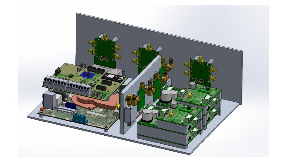
Breadboard for lab test DCDC converters Interface board Power amplifiers Flight computer RF splitter and phase shifters
Optional RF re-packaging for cubesat volume Duroid 4350 / FR-4 Trade Section Length Duroid Loss FR 4 Loss 1 (950 MHz) 1. 3 in 0. 11 d. B 0. 18 d. B 2 (7700 MHz) 0. 7 in 0. 20 d. B 0. 50 d. B 1. 5 + 4 d. B 3 (7700 MHz) Antenna switch 1. 0 in 0. 28 d. B 0. 71 d. B 1. 2 d. B 0. 59 d. B 1. 39 d. B 90° hybrid + mixer 3 splitter + phase shift Total loss 2 1 Part Loss Notes: Section 3 is the only one after the power amplifiers. Board layout is conceptual for trades – would be decreased in size and integrated with interface board for cubesat.
950 MHz +10 d. Bm 7. 3 -8. 2 GHz +15 d. Bm IF 2 Hybrid radio -3 d. B Df Df -4 d. B Df IF 1 mixer -8 d. B LO RF 7. 7 GHz -1 d. Bm 7. 7 GHz -5. 8 d. Bm splitter 7. 7 GHz -10 d. Bm LO
21. 5 mm (0. 847”) 1. 03 mm 0. 5 mm 3. 55 mm 18. 4 mm (0. 724”) 1. 93 mm 11. 627 mm (0. 458”) 2. 0 mm (0. 080”) 1. 28 mm (0. 050”) 17. 75 mm (0. 700”)