RF Lunch Learn Some basic definitions strait away

RF Lunch & Learn ● Some basic definitions strait away; I/Q data breakdown, common RF devices. ● Getting data OTA - Digital Modulation, Noise Spectral Density, Bit Energy, BER, etc… ● Receiver/Transmitter Architectures, Technology trends ● Transmission Lines ● Antennas
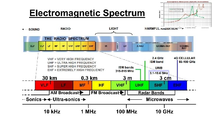

Why use higher frequency. . ? ● Primary drivers ○ ○ Bandwidth - large amounts Useable, unallocated space ● Good things ○ ○ ○ Smaller antennas, smaller circuits Lots of accessible components Drives innovation ● Bad things ○ ○ ○ Propagation characteristics Parasitic control Component selection

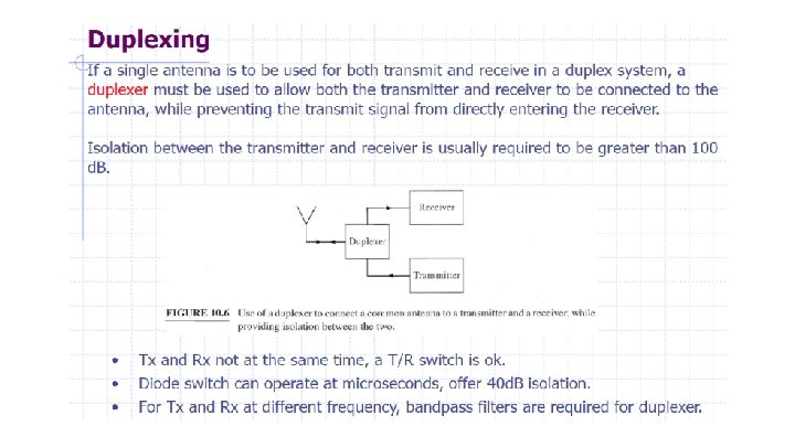
RF Communication Systems Simplex RF System - A radio technology that allows only one-way communication from a transmitter to a receiver. Examples: FM radio, Pagers, TV, One-way AMR systems. Half-duplex RF Systems - Operation mode of a radio communication system in which each end can transmit and receive, but not simultaneously. Applies to most TDD and TDMA systems. Examples: Walkie-talkie, wireless keyboard mouse. Full-duplex RF Systems - Radio systems in which each end can transmit and receive simultaneously. Typically two frequencies are used to set up the communication channel. Each frequency is used solely for either transmitting or receiving. Applies to Frequency Division Duplex (FDD) systems. Examples: Cellular phones, satellite communication

Why? Wide Dynamic Range of RF transceivers. http: //www. ti. com/lit/ml/slap 127. pdf

1 d. B Compression Point Parameter for evaluating the linearity of a non-linear device (gain compression). amplifiers, mixers, switches… Modulations that alter amplitude and phase information (QAM, QPSK, etc…) most impacted. Nonlinear transmitter performance results in degradation of signal and modulation quality, making it difficult for a demodulator at the receiver to recover the transmitted modulated information

Third Order Intercept / IP 3 If the signals are close together in frequency, some of the sum and difference frequencies called intermodulation products produced can occur within the bandwidth of the amplifier. IMD 3 components fall close to the signal passband. These cannot be filtered out, so they will ultimately become interfering signals to the main signals to be amplified.

Noise Figure ● ● Harold Friis ~ 1940’s The SNR will always be degraded as the signal passes through any microwave component! NF describes component and system level view of how much noise is contributed by your design. Minimize system NF with low noise, high gain device at the beginning of lineup.

Dynamic Range ● ● ● The dynamic range of a radio receiver is essentially the range of signal levels over which it can operate. The low end of the range is governed by its sensitivity whilst at the high end it is governed by its overload or strong signal handling performance. Typically taken as difference between TOI or 1 d. B point and the MDS. Be careful because often times these values are interchanged or referenced differently depending on manufacturer. Blocking, IMD, AGC https: //www. mwrf. com/test-and-measurement/understanding-dynamic-range

S Parameters Add some S parameters stuff

Why I & Q? ● ● ● Isn’t this good enough? Why I&Q? Positive or negative frequency? Peak amplitude? Envelope? Did we really sample at the peaks; how do we know? http: //whiteboard. ping. se/SDR/IQ ● https: //hackaday. com/2017/05/16/if-the-iand-q-of-software-defined-radio-are-your -nemesis-read-on/#more-252421

IQ ● I/Q Data solves this. Instead of looking at the signal as a flat curve as above, look at it as a helix in three dimensions. ● Now if you look at this curve from the side, you'll actually get the same graph as the first one above. Your "real" signal actually is this 2 D projection of this corkscrew signal. This is your "I" in I/Q data.

IQ ● Similar to I, Q is the projection of the helix onto the quadrature axis. ● Observing the I/Q set from the time axis shows the envelope and peak power. ● The direction of the I/Q data set’s progression indicates sign of the signal frequency.

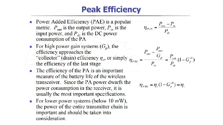
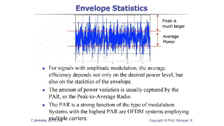
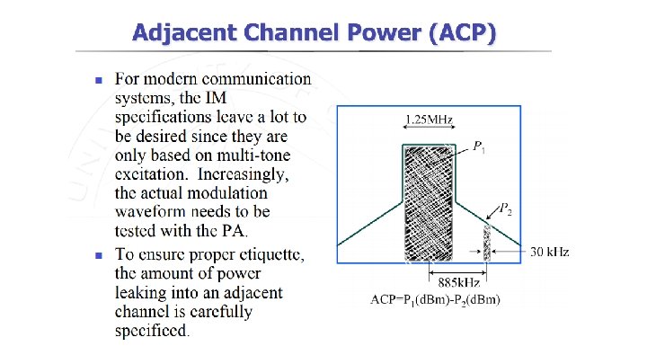
http: //rfic. eecs. berkeley. edu/~niknejad/ee 242/pdf/eecs 242_lect 15_PAs. pdf

Mixers ● ● ● RF Mixers are 3 -port active or passive devices. They are designed to yield both, a sum and a difference frequency at a single output port when two distinct input frequencies are inserted into the other two ports. Introduces IMD, spurs, and other unwanted emissions. Conversion gain/loss, IP, port isolation, spurious rejection, image response https: //www. qsl. net/va 3 iul/RF%20 Mixers/RF_Mixers. pdf

Filters ● Active circuit / passive ● Elliptic, Chebyshev, Butterworth, etc. responses ● Gain & Phase flatness ● Ceramic, SAW, LC/lumped Heavy, lossy, expensive, large element footprint - not SWa. P friendly ● Common to implement as Band Select, IF, Duplexer - stages where letting other signals into the system would significantly degrade performance / selectivity.

Frequency Planning ● ● ● IF Non-linear components introduce spurious components (such as the seen at the mixer output after downconversion). Image rejection? Other frequencies nearby the RF interest band that could create IM products? - Preselector

Frequency Planning ● ● A preselector or duplex filter prior to the mixer RF input will remove out of band signals; stopping them from mixing with the LO and interfering with signal at IF. Spurious in band signals may not be able to be filtered thus importance on paying attention to system IM performance.
 ● Make an IQ modulator with only a sig")
Mixers, Quadrature Amplitude Modulator (QAM) ● Make an IQ modulator with only a sig gen (LO), quadrature hybrid, some diode ring mixers and a combiner. QPSK signal easily modulated onto the carrier by changing the signs of I and Q. https: //youtu. be/RHFZUq. UM 8 DY? t=103

Modulation

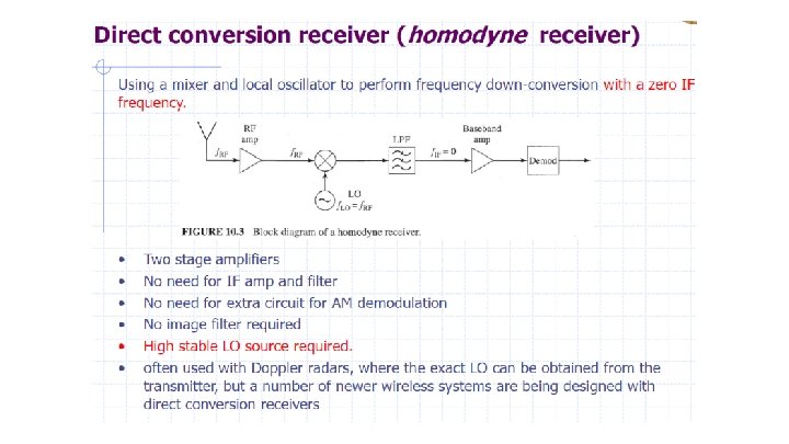
Receiver Architectures ● ● Low Noise Figure https: //www. analog. com/media/en/technical-documentation/techarticles/Review-of-Wideband-RF-Receiver-Architecture-Options. pdf

Frequency planning! IF frequency is critical, as well as preselector and IF filter characteristics.

Direct Sampling Receiver ● ● ● Digitization of very wide instantaneous bandwidth at the L- and S-bands. As converters continue to evolve, direct RF sampling at other bands (such as C- and X-bands) will likely become viable as well. Decreased cost per channel, less dense, simplify RF chain. Limited by ADC BW

u. Wave RFIC

ML Modulation Ident. - AT & ARCO https: //www. c 4 isrnet. com/electronic-warfare/2018/08/27/army-announces-winners-of-ai-for-electronicwarfare-challenge/

Putting the pieces together - Transmission lines ● ● ● ● Coax Microstrip VSWR Impedance Velocity Factor TL’s as stubs TL’s as transformers https: //urgentcomm. com/2002/02/01/technical-techniques-a-primer-for-transmission-lines-2/

Antennas ● Looks to be some good stuff here: http: //www. ti. com/lit/ml/slap 127. pdf

Things to check out if RF interests you. . . ● Tutorial on High-Power Balanced & Doherty Microwave Amplifiers ● https: //www. indiegogo. com/projects/kerberossdr-4 x-coherent-rtl-sdr#/ ; youtube: Signals. Everywhere ● All your RFz are belong to me - Balint Seeber ● Decoding the Lo. Ra phy - Matt Knight
- Slides: 48