
RF Distribution Alternatives R A Yogi FREIA group

RF Distribution Alternatives R. A. Yogi & FREIA group Uppsala University.
ESS : pulsed spallation source producing neutrons for scientific research • consists of proton linear accelerator, target, neutron beam lines • neutrons are extracted in fission process from their bound states in heavy atomic nuclei. • Energy required for fission process is created by bombarding nuclei with high energy protons, so proton accelerator is needed.
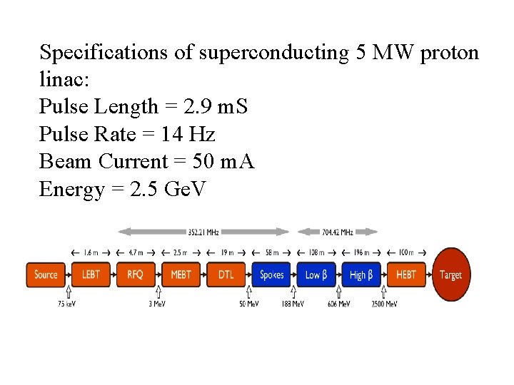
Specifications of superconducting 5 MW proton linac: Pulse Length = 2. 9 m. S Pulse Rate = 14 Hz Beam Current = 50 m. A Energy = 2. 5 Ge. V
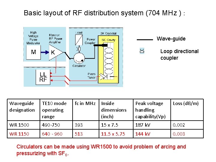
Basic layout of RF distribution system (704 MHz ) : Wave-guide Loop directional coupler Waveguide designation TE 10 mode operating range fc in MHz Inside dimensions (inch) Peak voltage handling capability(Vp) Loss (d. B/m) WR 1500 490 -750 393 15 x 7. 5 187 k. V 0. 002 WR 1150 640 - 960 513 11. 5 x 5. 75 144 k. V 0. 003 Circulators can be made using WR 1500 to avoid problem of arcing and pressurizing with SF 6.
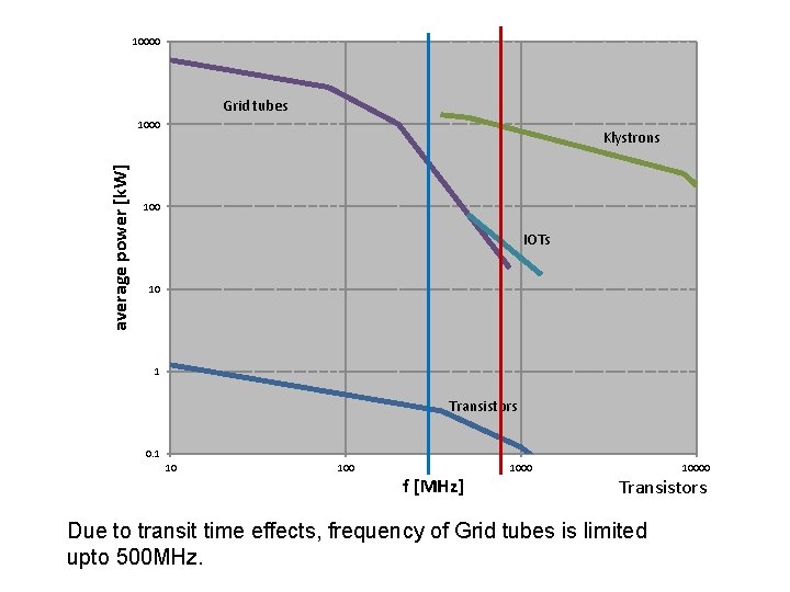
10000 Grid tubes average power [k. W] 1000 Klystrons 100 IOTs 10 1 Transistors 0. 1 10 100 f [MHz] 10000 Transistors Due to transit time effects, frequency of Grid tubes is limited upto 500 MHz.
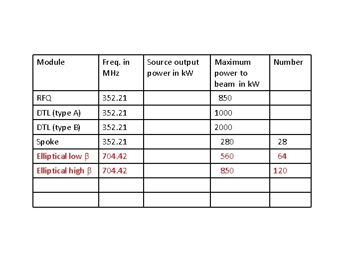
Module Freq. in MHz Source output power in k. W Maximum power to beam in k. W Number RFQ 352. 21 850 DTL (type A) 352. 21 1000 DTL (type B) 352. 21 2000 Spoke 352. 21 280 28 Elliptical low 704. 42 560 64 Elliptical high 704. 42 850 120
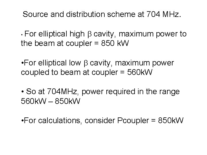
Source and distribution scheme at 704 MHz. elliptical high cavity, maximum power to the beam at coupler = 850 k. W • For elliptical low cavity, maximum power coupled to beam at coupler = 560 k. W • So at 704 MHz, power required in the range 560 k. W – 850 k. W • For calculations, consider Pcoupler = 850 k. W
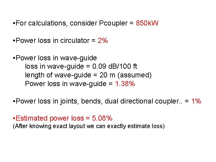
• For calculations, consider Pcoupler = 850 k. W • Power loss in circulator = 2% • Power loss in wave-guide = 0. 09 d. B/100 ft length of wave-guide = 20 m (assumed) Power loss in wave-guide = 1. 38% • Power loss in joints, bends, dual directional coupler. . = 1% • Estimated power loss = 5. 08% (After knowing exact layout we can exactly estimate loss)
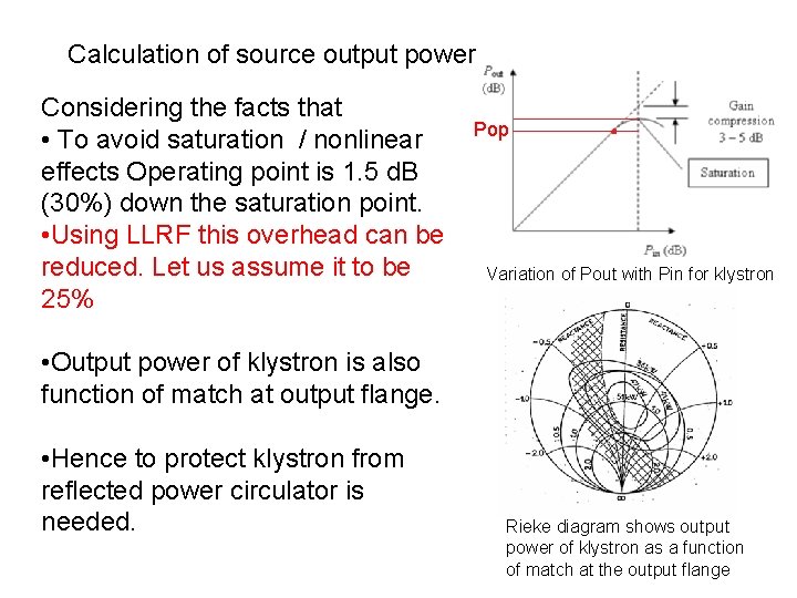
Calculation of source output power Considering the facts that • To avoid saturation / nonlinear effects Operating point is 1. 5 d. B (30%) down the saturation point. • Using LLRF this overhead can be reduced. Let us assume it to be 25% Pop Variation of Pout with Pin for klystron • Output power of klystron is also function of match at output flange. • Hence to protect klystron from reflected power circulator is needed. Rieke diagram shows output power of klystron as a function of match at the output flange
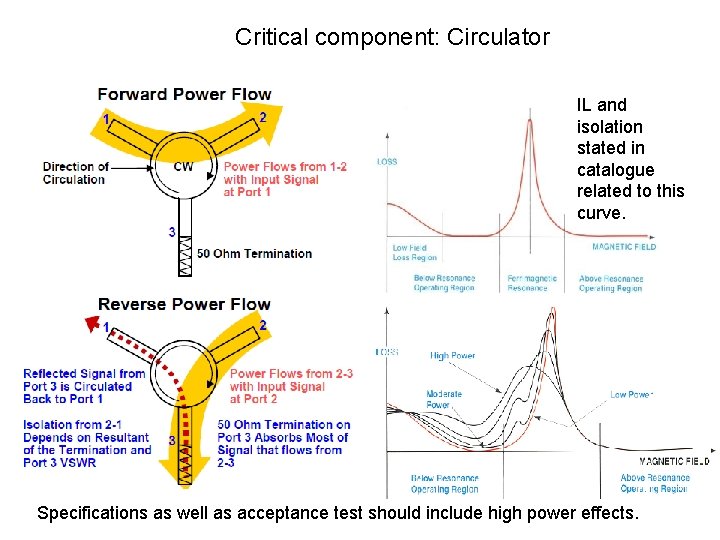
Critical component: Circulator IL and isolation stated in catalogue related to this curve. Specifications as well as acceptance test should include high power effects.
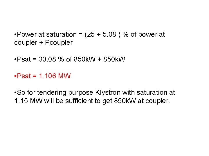
• Power at saturation = (25 + 5. 08 ) % of power at coupler + Pcoupler • Psat = 30. 08 % of 850 k. W + 850 k. W • Psat = 1. 106 MW • So for tendering purpose Klystron with saturation at 1. 15 MW will be sufficient to get 850 k. W at coupler.
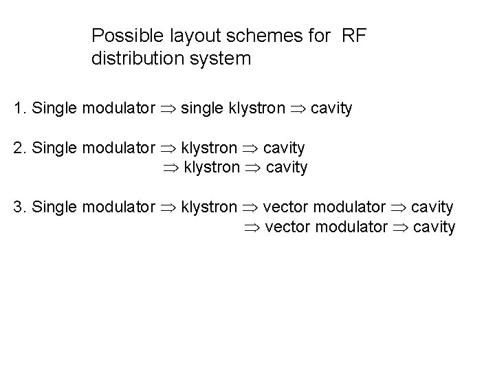
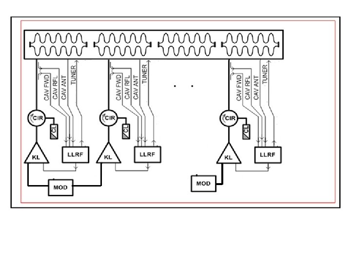
Possible layout schemes for RF distribution system 1. Single modulator single klystron cavity 2. Single modulator klystron cavity 3. Single modulator klystron vector modulator cavity
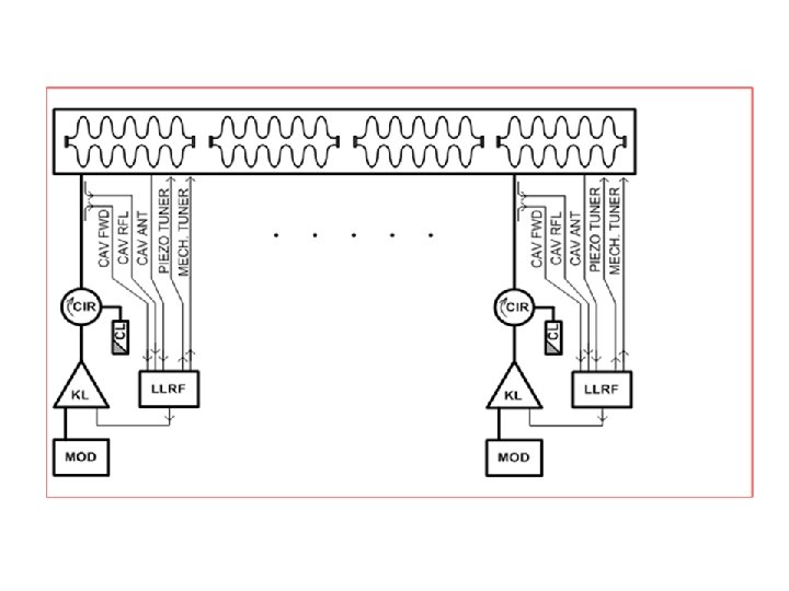
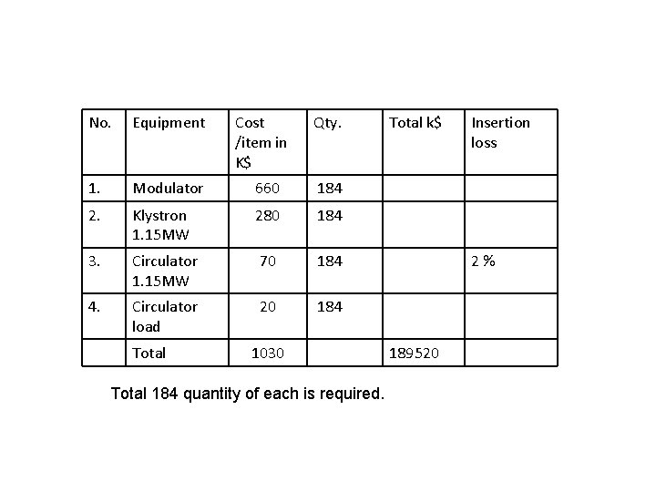
No. Equipment 1. Modulator 660 184 2. Klystron 1. 15 MW 280 184 3. Circulator 1. 15 MW 70 184 4. Circulator load 20 184 Total Cost /item in K$ Qty. 1030 Total 184 quantity of each is required. Total k$ Insertion loss 2% 189520
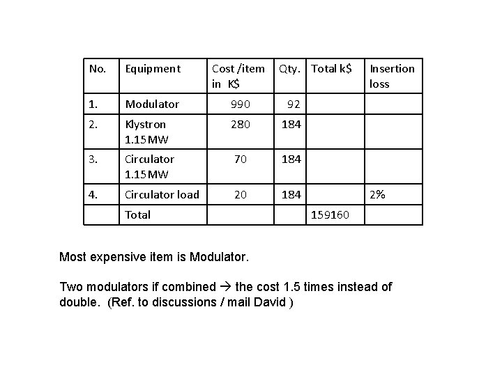
No. Equipment Cost /item in K$ 1. Modulator 990 92 2. Klystron 1. 15 MW 280 184 3. Circulator 1. 15 MW 70 184 4. Circulator load 20 184 Total Qty. Total k$ Insertion loss 2% 159160 Most expensive item is Modulator. Two modulators if combined the cost 1. 5 times instead of double. (Ref. to discussions / mail David )
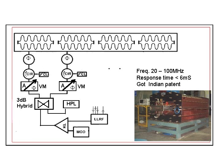
A VM 3 d. B Hybrid A VM HPL Freq. 20 – 100 MHz Response time < 6 m. S Got Indian patent
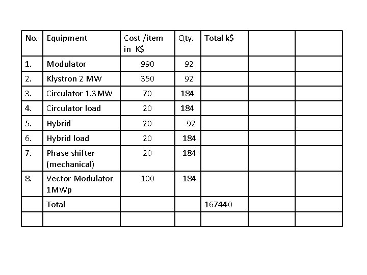
No. Equipment Cost /item in K$ Qty. 1. Modulator 990 92 2. Klystron 2 MW 350 92 3. Circulator 1. 3 MW 70 184 4. Circulator load 20 184 5. Hybrid 20 92 6. Hybrid load 20 184 7. Phase shifter (mechanical) 20 184 8. Vector Modulator 1 MWp 100 184 Total k$ 167440
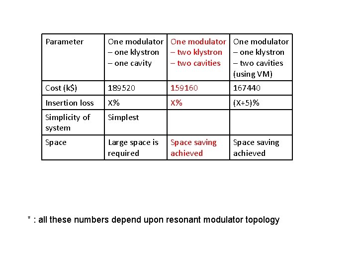
Parameter One modulator – one klystron – two klystron – one cavity – two cavities (using VM) Cost (k$) 189520 159160 167440 Insertion loss X% X% (X+5)% Simplicity of system Simplest Space Large space is required Space saving achieved * : all these numbers depend upon resonant modulator topology
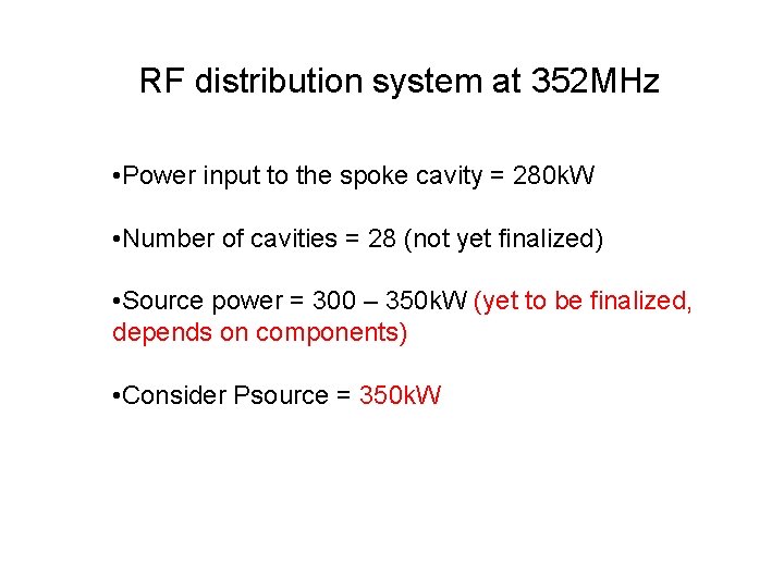
RF distribution system at 352 MHz • Power input to the spoke cavity = 280 k. W • Number of cavities = 28 (not yet finalized) • Source power = 300 – 350 k. W (yet to be finalized, depends on components) • Consider Psource = 350 k. W
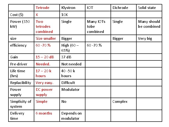
Tetrode Klystron Cost ($) X 10 X Power (350 k. W) Two tetrodes combined Single size Size smaller Bigger efficiency 60 -70 % High (60 – 65%) Gain 15 – 20 d. B 37 d. B Pre-driver Needed. Not needed Life time (hrs) 17 – 20 k hours 40 -50 k hours Replacibility Very easy. Difficult Power supply DC power supply Modulator Simplicity of system Simple No Delivery time 6 months Depends on modulator IOT Dichrode Solid state Many IOTs tobe combined Single Many should be combined Bigger Very big 60 -70 % Complex
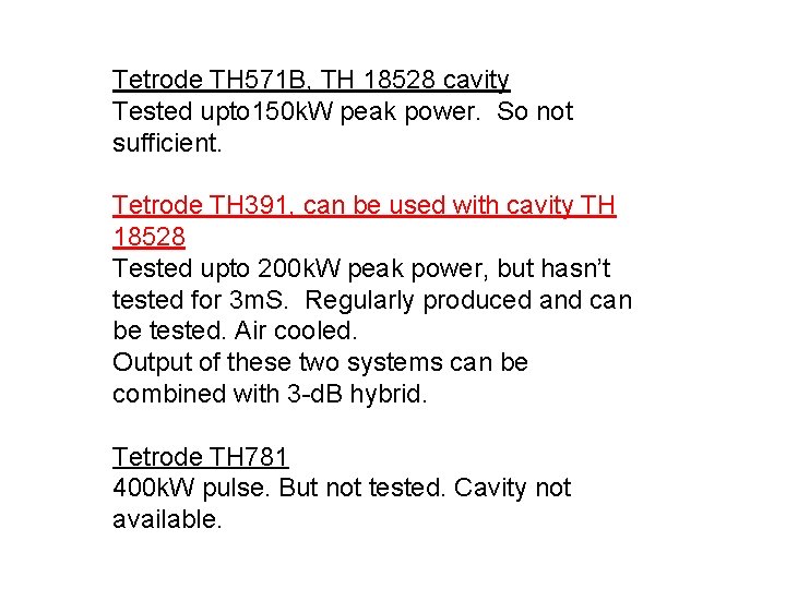
Tetrode TH 571 B, TH 18528 cavity Tested upto 150 k. W peak power. So not sufficient. Tetrode TH 391, can be used with cavity TH 18528 Tested upto 200 k. W peak power, but hasn’t tested for 3 m. S. Regularly produced and can be tested. Air cooled. Output of these two systems can be combined with 3 -d. B hybrid. Tetrode TH 781 400 k. W pulse. But not tested. Cavity not available.
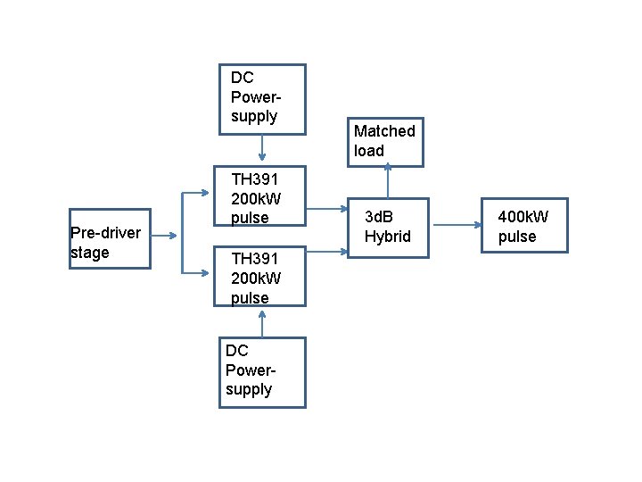
DC Powersupply Pre-driver stage TH 391 200 k. W pulse DC Powersupply Matched load 3 d. B Hybrid 400 k. W pulse

Thank you ! Questions and suggestions are welcome.
- Slides: 24