Review Half Wave Full Wave Rectifier Center tapped


- Slides: 13
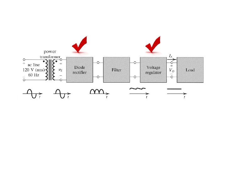
Review • Half Wave • Full Wave Rectifier • Center tapped • Bridge • Rectifier Parameters • PIV • Duty Cycle
Filters Ø A capacitor is added in parallel with the load resistor of a half-wave rectifier to form a simple filter circuit. At first there is no charge across the capacitor Ø During the 1 st quarter positive cycle, diode is forward biased, and C charges up. Ø VC = VO = VS - V. Ø As VS falls back towards zero, and into the negative cycle, the capacitor discharges through the resistor R. The diode is reversed biased ( turned off) Ø If the RC time constant is large, the voltage across the capacitor discharges exponentially.
Filters Ø During the next positive cycle of the input voltage, there is a point at which the input voltage is greater than the capacitor voltage, diode turns back on. Ø The diode remains on until the input reaches its peak value and the capacitor voltage is completely recharged.
Vp Vm Quarter cycle; capacitor charges up Capacitor discharges through R since diode becomes off VC = Vme – t / RC Input voltage is greater than the capacitor voltage; recharge before discharging again NOTE: Vm is the peak value of the capacitor voltage = VP - V Since the capacitor filters out a large portion of the sinusoidal signal, it is called a filter capacitor.
Ripple Voltage, and Diode Current ØVr = ripple voltage Tp ØVr = VM – VMe -T’/RC T’ where T’ = time of the capacitor to discharge to its lowest value Vr = VM ( 1 – e -T’/RC ) Expand the exponential in series, Vr = ( VMT’) / RC Figure: Half-wave rectifier with smoothing capacitor.
• If the ripple is very small, we can approximate T’ = Tp which is the period of the input signal • Hence for half wave rectifier Vr = ( VMTp) / RC l For full wave rectifier Vr = ( VM 0. 5 Tp) / RC
Example Consider a full wave center-tapped rectifier. The capacitor is connected in parallel to a resistor, R = 2. 5 k. The input voltage has a peak value of 120 V with a frequency of 60 Hz. The output voltage cannot be lower than 100 V. Assume the diode turn-on voltage, V = 0. 7 V. Calculate the value of the capacitor. VM = 120 – 0. 7 = 119. 3 V Vr = 119. 3 – 100 = 19. 3 V 19. 3 = 119. 3 / (2*60*2500*C) C = 20. 6 F
Example Consider a full wave bridge rectifier. The capacitor C = 20. 3 F is connected in parallel to a resistor, R = 10 k. The input voltage, vs = 50 sin (2 (60)t). Assume the diode turn-on voltage, V = 0. 7 V. Calculate the value of the ripple voltage. Frequency = 60 Hz VM = 50 – 1. 4 = 48. 6 V Vr = 48. 6 / (2*60*10 x 103*20. 3 x 10 -6) Vr = 2 V
The full-wave rectifier circuit is shown in the figure below. The output peak current of the circuit is 200 m. A when the peak output voltage is 12 V. Assume that input supply is 120 V(rms), 60 Hz and diode cut-in voltage Vγ = 0. 7 V. Find the required value of C for limiting the output ripple voltage, Vr = 0. 25 V. Answer: C = 6. 67 m. F
MULTIPLE DIODE CIRCUITS
Example 1 Cut-in voltage of each diode in the circuit shown in Figure is 0. 65 V. If the input voltage VI = 5 V, determine the value of R 1 when the value of ID 2 = 2 ID 1. Also find the values of Vo, ID 1 and ID 2. Assume that all diodes are forwardbiased.
Example 2 The figure shows a multiple diode circuit. If each diode cut-in voltage is Vγ= 0. 7 V, determine ID 1, ID 2 and VO for R 2 = 1. 1 k. Answers: ID 1 = 1 m. A ID 2 = 6 m. A VO = 2. 3 V