Review Half Wave Full Wave Rectifier Center tapped


- Slides: 18
Review • Half Wave • Full Wave Rectifier • Center tapped • Bridge • Rectifier Parameters • PIV • Duty Cycle
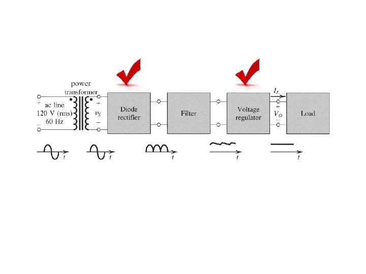
Filters Ø A capacitor is added in parallel with the load resistor of a half-wave rectifier to form a simple filter circuit. At first there is no charge across the capacitor Ø During the 1 st quarter positive cycle, diode is forward biased, and C charges up. Ø VC = V O = V S - VD Ø As VS falls back towards zero, and into the negative cycle, the capacitor discharges through the resistor R. The diode is reversed biased ( turned off) Ø If the RC time constant is large, the voltage across the capacitor discharges exponentially.
Filters Ø During the next positive cycle of the input voltage, there is a point at which the input voltage is greater than the capacitor voltage, diode turns back on. Ø The diode remains on until the input reaches its peak value and the capacitor voltage is completely recharged.
Vpeak VM Quarter cycle; capacitor charges up Capacitor discharges through R since diode becomes off VC = VMe – t / RC Input voltage is greater than the capacitor voltage; recharge before discharging again NOTE: Vm is the peak value of the output voltage Since the capacitor filters out a large portion of the sinusoidal signal, it is called a filter capacitor.
Ripple Voltage, and Diode Current ØVr = ripple voltage Tp ØVr = VM – VMe -T’/RC T’ where T’ = time of the capacitor to discharge to its lowest value Vr = VM ( 1 – e -T’/RC ) Expand the exponential in series, Vr = ( VMT’) / RC Figure: Half-wave rectifier with smoothing capacitor.
• If the ripple is very small, we can approximate T’ = Tp which is the period of the input signal • Hence for half wave rectifier Vr = ( VMTp) / RC l For full wave rectifier Vr = ( VM 0. 5 Tp) / RC
Example Consider a full wave center-tapped rectifier. The capacitor is connected in parallel to a resistor, R = 2. 5 k. The input voltage has a peak value of 120 V with a frequency of 60 Hz. The output voltage cannot be lower than 100 V. Assume the diode turn-on voltage, V = 0. 7 V. Calculate the value of the capacitor. VM = Vo peak = 120 - VD 120 – 0. 7 = 119. 3 V Vr = 119. 3 – 100 = 19. 3 V 19. 3 = 119. 3 / (2*60*2500*C) C = 20. 6 F
Example Consider a full wave bridge rectifier. The capacitor C = 20. 3 F is connected in parallel to a resistor, R = 10 k. The input voltage, vs = 50 sin (2 (60)t). Assume the diode turn-on voltage, V = 0. 7 V. Calculate the value of the ripple voltage. Frequency = 60 Hz VM = Vo peak = 50 – 2 VD 50 – 1. 4 = 48. 6 V Vr = 48. 6 / (2*60*10 x 103*20. 3 x 10 -6) Vr = 2 V
The full-wave rectifier circuit is shown in the figure below. The output peak current of the circuit is 200 m. A when the peak output voltage is 12 V. Assume that input supply is 120 V(rms), 60 Hz and diode cut-in voltage Vγ = 0. 7 V. Find the required value of C for limiting the output ripple voltage, Vr = 0. 25 V. Answer: C = 6. 67 m. F
Clipper Circuit
• Clipper – is used to eliminate portion of a signal that are above or below a specified level i. e the clip value • Step #1: Determine the clip value • Step #2: Set the conditions
● Clipper circuits, also called limiter circuits, are used to eliminate portion of a signal that are above or below a specified level – clip value. ● The purpose of the diode is that when it is turn on, it provides the clip value ● Clip value = V’. To find V’, use KVL at L 1 ● The equation is : V’ – VB - V = 0 V’ = VB + V Vi L 1 Ø Then, set the conditions Ø If Vi > V’, diode conducts, hence Vo = V’ Ø If Vi < V’, diode off, open circuit, no current flow, Vo = Vi V’ = VB + V
Clippers Ø Other clipping circuits can be constructed by reversing the diode, the or the polarity of the voltage VB. • V’ = VB - V • conditions: Vi > V’ off, Vo = Vi Vi < V’ conducts, Vo = V’ • V’ = - VB + V • conditions: Vi > V’ conducts, Vo = V’ Vi < V’ off, Vo = Vi • V’ = - VB - V • conditions: Vi > V’ off, Vo = Vi Vi < V’ conducts, Vo = V’
Parallel Based Clippers Ø Positive and negative clipping can be performed simultaneously by using a double limiter or a parallel-based clipper. Ø The parallel-based clipper is designed with two diodes and two voltage sources oriented in opposite directions. Ø This circuit is to allow clipping to occur during both cycles; negative and positive
Example 1 • Consider the parallel clip circuit shown below. Assume the VZ 1 = 6 V and VZ 2 = 4 V and V = 0. 7 V. Given Vi = 10 sin t, sketch VO
II = I Z + IL Equate them and assume IZmin = 0. 1 IZmax Range of supply voltage Voltage Regulator Zener Diode CHAPTER 3 The load resistor sees a constant voltage regardless of the current VZ = V L
If the ripple is very small, we can approximate T’ = Tp where Tp is the period of the cycle Capacitor Discharge Vm is the peak value of the output voltage Clipper Ripple Voltage, Vr Vo = Vs - VD Filter Vo = Vs - 2 VD PIV = 2 Vspeak - VD Duty Cycle Centertapped Full Wave CHAPTER 3 Rectifier Half Wave Bridge PIV = Vspeak - VD Vo = Vs - VD PIV = Vspeak