RETROFITTING OF WELL FOUNDATION Shri M Suyambulingam IRSE

RETROFITTING OF WELL FOUNDATION Shri. M. Suyambulingam , IRSE, Chief Engineer/ S. Railway

SYNOPSIS Ø Well foundations are deep foundations having heavy mass & constructed to high standards and hence have enormous reserve capacity in carrying loads. Ø whenever steel girders are programmed to be replaced into PSC girder/ slab bridges having heavy dead load retrofitting is necessary. Also to carry heavy haul trains, 25 t axle load etc. , foundation need to be strengthened. Ø In this paper, for enhancing the carrying capacity of well foundation, system of secondary foundation in the form of under reamed piles combined with jacketing of the piers & wells are suggested and designed for adoption.

WELL FOUNDATION Well Foundations are very strong and sturdy foundations suitable for, Ø Carrying heavy axle loads. Ø Stable against sliding, overturning etc. , Ø Due to heavy mass below ground level, C. G is lowered & gets anchored. Ø More suitable to carry earthquake loads. Ø Has enormous reserve capacity/ strengthen all directions.

RETROFITTING OF WELL FOUNDATION Ø Well foundations often get exposed at many locations due to large amount of scour / sand mining problems (Br. No. 482, Br. No. 167; kuzhithurai river Br. 161…. etc. , ). Ø Strength of existing well foundations which need to be augmented to carry (cc+8+2) , 25 t loading…etc. , Ø The existing old well foundations are proposed to be strengthened using RCC Ring / Grade Beam surrounding the well upto the scoured Bed level supported by under reamed piles of required capacity at suitable centers below the ring grade beam. Ø The piles are taken atleast upto the bottom level of well foundation.
 acts as")
THE LOAD TRANSFER MECHANISM Ø The annular RC capping slab (Ring beam) acts as a spread footing and carries/transmits part of the super imposed loads. Ø The jacketed pier distributes the load over large bearing area and hence the intensity of loading gets reduced. Ø Self weight of pier is assumed to be carried by well structure itself. To be continued…

continues…. As per IS 2911 para 5. 2. 7. 2, spacing of U/R piles is < 1. 5 Du and >3 m. Ø Hand augured cylindrical piles (without under reaming) can also be used in the case of non clayey soil. Ø Due to large annular bearing area at the base of the eroded bed level, stability of the well gets enhanced. Ø IS-2911 provide a ready table for the carrying capacity of small diameter U/R piles for various diameter & bulbs (Table 1). Ø

Well foundation-superior structural system Foundation adopted where soil strata comprise of sand or stiff clay. Ø Size and shape of well depends on the size of pier, feasibility of dredging…. etc. , Ø Weight/m 2 of peripheral surface is higher which facilitates sinking of well. Ø Load transfer is by end bearing and SBC of soil determines the size of well. Ø

When strengthened by piles all round during ground motion Vertical hold-down improves and hence response during ground motion. Ø Soil- structure interaction gets enhanced. Ø Capacity design is achieved by inhibiting undesirable in-elastic deformation during earthquake. Ø Tests conducted at SERC / Chennai has proved that v. Dynamic characteristics such as natural frequencies. v%damping, resonant acceleration response and normalized resonant displacement response are superior when SCC is used. Ø
 can be advantageously used for these")
SCC for Under reamed piles Self compacting concrete(SCC) can be advantageously used for these hand bored piles. Ø SCC when mixed with admixture give early strength & exhibit better characteristics and denser concrete. Ø 53 grade OPC with SCM (supplemental cement material) as partial replacement produced higher durable concrete up to 80 Mpa. Ø
 Ø Vertical")
THE INCREASE OF LOAD INTENSITY (Steel girder if replaced into PSC ‘U’) Ø Vertical load due to ‘U’ type PSC girder for 18. 3 m of railway span is of the order of 145 t (compared to approx. 26 t due to steel girder) =500% increase. Ø The lateral forces due to earthquake oscillation get increased by 150%. Ø LL for double span condition = 81. 4 t. Total load= 447 t. Ø Longitudinal force = 2 x 14. 99 t on the well. Ø Water pressure = 4. 5 t. Ø Total lateral force = 34. 57 t.

Piles (8 NO. S 500 mm dia OR 16 No. s 300 mm Dia
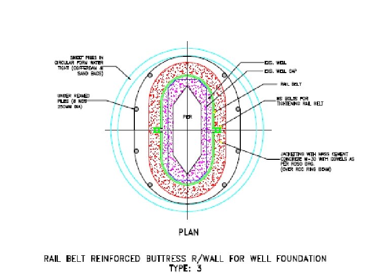

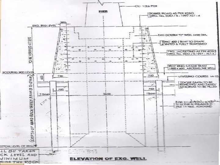
STRENGTHENING OF WELL FOUNDATIONANALOGY Ø The newly provided under reamed piles are designed to carry 80% - 100% of the loads. Ø The well portion is strengthened by jacketing around the well as per RDSO drg. no. EDO/B/1997/ALT-4. Ø 2 layers of ISMC channels bent to shape are also clamped vertically around the well, fully tightened so as to confine the exposed portion of well above the scoured bed level. Ø Due to load, when well starts settling/ sinking, the ISMC acting as belt around, holds the well back into the embedded concrete. To be continued….

CONTINUES …. Ø The triangle shaped concrete with dowels surrounding the well transmit loads/forces to the annular ring beam. Ø The ring beam transfers load to the U/R piles & resting at the scoured bed level. Ø Capping ring beam supported on fully - compacted gravel / quarry dust also provide additional bearing area for load transfer (Not considered in design). Ø Buoyancy effect on this ring beam is neglected. Ø Increase in strength due to ageing of concrete is also not considered.
 MAS – GDR SECTION (Sullurpettai)")
BR. NO. 167 (Span -11 X 18. 29 m) MAS – GDR SECTION (Sullurpettai) WELL FOUNDATION Retrofitted with U/R PILES- DOUBLE REAMED

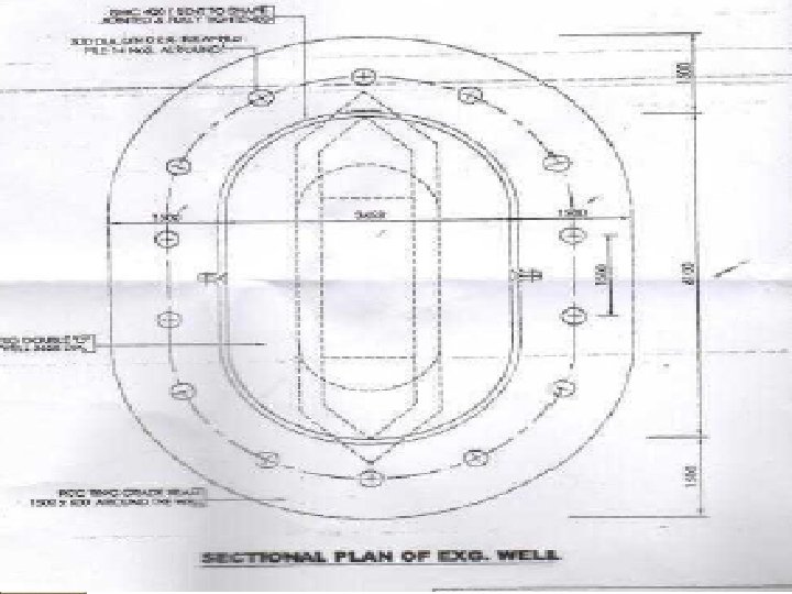
STRENGTHENING OF EXG. OLD WELL FOUNDATION WITH RING BEAM AND UNDER REAMED PILES: (P 8 & P 11) 500∅ Double Under Reamed Piles (P 8 & P 11 - Shallow wells): - Depth below Scoured Bed level - Piles upto the bottom of well foundation. - No. of Piles = 8 No. s - Well Diameter = 3. 66 m - Ring beam / girder at scoured bed level = 1500 x 800 thick (4/16 ∅ reinf. at top 4/125 ∅ reinf. at bottom 10∅ reinf. 4 legged stirrups at 150 cm. ) - Piles = 12 / 12 ∅ Reinf. Rods. (8 ∅ reinf. Rings @ 300 cm. ) - Capacity of 8 no. s of 500 ∅ Double under reamed piles = 796 t > 447 t - Capacity of 8 no. s of 500 ∅ piles in horizontal direction = 43. 20 t >34. 57 t = 9. 58 m.

STRENGTHENING OF EXG. OLD WELL FOUNDATION WITH RING BEAM AND UNDER REAMED PILES: (P 8 & P 11) For pier no. P 8: - Depth below Bed level = 7’ + 31’ + 4’ = 44’ = 13. 41 m - Depth below Scoured Bed level = 13. 41 – 3. 83 = 9. 58 m - Diameter of well = 4. 250 m As per table 1 of IS 2911 -3 - Diameter of pile d = 30 cm - Underreamed of Pile=2. 5 d = 75 cm - Length of Double Under reamed Pile = 3. 5 m - Compression load for Double under reamed pile = 24 t ( from IS 2911, table. 1) - Increase per 30 cm length = 1. 40 t - Length of grip (depth)9. 58 – 3. 5 = 6. 08 m - Multiples of 30 cm 6. 08 / 0. 30(hence extra capacity. = 20. 27 x 1. 40 = 28. 378 t - Capacity of each pile = 24 + 28. 378 = 52. 378 t

STRENGTHENING OF EXG. OLD WELL FOUNDATION WITH RING BEAM AND UNDER REAMED PILES: (P 8 & P 11) As per table 1 of IS 2911 -3 - Spacing = 2. 0 x 0. 75 =1. 50 m Clause 5. 2. 7 of IS: 2911 (Part III) - Circumference of well along pile centre = 21 m - No. of under reamed pile = 21/1. 50 = 14 say 16 no. s - Capacity = 16 x 52. 378 =838 t > 447 t - Lateral thrust capacity for double under = 2. 4 t - For 16 No's , total lateral capacity. = 16 x 2. 4 = 38. 4 t > 34. 5 t(i. e. , longitudinal force) Design of circular Grade Beam: (Double ‘D’ shaped grade beam) - Dia. of grade beam - Moment coefficients in circular grade beam: - Load /m run: (DL =142 t+LL=81. 65 t=223. 6 t) = 223653/(п x 5. 00) = 14245 Kg/m - With piles as columns(-ve B. M@ support) = 0. 0342 w. l - With piles as columns (+ve B. M @ support) = 0. 0176 w. l - Span l = 50 / 2 2. 5 m. = = 5. 00 m

IS 2911 – Part III - 1980

STRENGTHENING OF EXG. OLD WELL FOUNDATION WITH RING BEAM AND UNDER REAMED PILES: (P 8 & P 11) Design of circular Grade Beam: (Double ‘D’ shaped grade beam) - Max. Twisting Moment = 0. 0053 w. l - Max. –ve moment @ support = 0. 0342 x 223653 x 2. 5 = 19122 Kg m - Max. +ve moment @ centre of span = 0. 0176 x 223653 x 2. 5 =9841 Kg m - Max. torsional moment @ 15° 12’ from either support (T). = 0. 0053 x 223623 x 2. 5 =2963 Kg m - Shear Force @ support section v = (14245 x 2. 5 x (п/4)) / 2 =27957 Kg Design of support section: (600 x 1000) - Effective ‘d’ = 600 – 75 – 12. 5 = 512. 5 - Equivalent Shear Force ‘Ve’ = V + (1. 6 T)/b = 27957 + (1. 6 )(2963) (100) 100 = 32698 Kg -

STRENGTHENING OF EXG. OLD WELL FOUNDATION WITH RING BEAM AND UNDER REAMED PILES: (P 8 & P 11) Design of support section: (600 x 1000) - Equivalent nominal shear stress Zve = 32698 / (50 x 71. 25) = 9. 18 Kg/cm 2 < 19 Kg /cm 2 (for M 25 grade concrete) Longitudinal Reinforcement: - Equivalent Bending Moment Me 1 = M + Mt - M = B. M @ cross section - Mt = T (1 + D/b) / 1. 7 - Where ‘T’ is the Torsional moment, ‘D’ is the overall depth and ‘b’ is the Breadth of beam Mt = 296300 (1 + 80/50) / 1. 7 =453165 Kg. cm Me 1 = 453165 + 1912200 =2365365 Kg. cm A ∅t = 2365365 / (2000 x 0. 894 x 51. 25) =25. 81 cm 2

STRENGTHENING OF EXG. OLD WELL FOUNDATION WITH RING BEAM AND UNDER REAMED PILES: (P 8 & P 11) Longitudinal Reinforcement: - Provide 4/25 ∅ rods (25. 81 cm 2 - 100 x A st / bd = (100 x 19. 625) / (50 x 51. 25) =0. 551 - Zc = 3. 26 Kg /cm 2 - Distance between the centres of corner = bars parallel to the width 50 – 2(5+1. 25) = 37. 5 cm – b 1 - Distance between the centre of corner = bars parallel to the depth 80 – 2 (5 + 1. 25) = 67. 5 cm = d 1 Transverse Reinforcement ( Cl. 41. 4. 30 IS 456) - Two legged closed Loops enclosing the corner longitudinal bars shall have on Area of cross section Asu, given by = 3. 14 = Therefore, Sv = (T Sv / b 1 d 1 σ sv) + (V Sv / 2. 5 d 1 σ sv) 0. 073 Sv + 0. 103 Sv 17. 84 cm

STRENGTHENING OF EXG. OLD WELL FOUNDATION WITH RING BEAM AND UNDER REAMED PILES: (P 8 & P 11) Total traverse reinforcement shall not be less than - (Zve – Zc) b. Sv / σ sv = - Therefore, Sv = (10. 51 – 3. 26) (50) (15) /1600. Sv 3. 40 cm 2 - Provide 10 mm ∅ 4 –leg stirrups @ 150 mm Centre to centre - Steel for moment @ mid span - Moment = - (9841 x 100 )/( 2000 x 0. 894 x 71. 25) = 7. 72 cm 2 - Provide 4 / 16 t. Rod = 8. 03 cm 2 - 9841 Kg m With 250 ∅ Piles (ALTERNATE) - Min. Spacing = 1. 5 Du - Generally = 2. 0 Du - Du = - Spacing = 2. 5 D = 2. 5 x 0. 25 = 0. 625 m 2 x 0. 625 = 1. 25 m

STRENGTHENING OF EXG. OLD WELL FOUNDATION WITH RING BEAM AND UNDER REAMED PILES: (P 8 & P 11) With 16 No. s of double underreamed piles Increase in capacity beyond 3. 5 m length = 6. 08 / 0. 30 x 1. 15 = 23. 31 t Capacity of 1 pile = 18 + 23. 31 = 41 t Capacity of 16 No. s of piles = 16 x 41 (vertical load) =656 t > 447 t Capacity for lateral thrust = 16 x 1. 8 = 28. 8 t only < 34. 57 t. Inadequate. Min. No. s of piles required. = 20 O. K. since capacity is (from lateral load point of view) 20 x 18=36 t. Hence ok. Min. Spacing = 1. 5 x 0. 625 = 0. 94 m 21/ 20 = 1. 05 m spacing Adopt 16 No. s. of 300 mmΦ U/R piles
 TVC – NCJ SECTION (")
BR. NO. 482 (Span -7 X 12. 20 m) TVC – NCJ SECTION ( Nambe River) WELL FOUNDATION Retrofitted with U/R PILES- DOUBLE REAMED

THE PROBLEM Ø Due to sand mining by local villagers the well foundation has got a deep scour of 3 m. Ø Very tall bridge with 7. 5 m pier above the well. Ø Well is resting on silty sandy bed. Ø Steep bed slope and heavy water flow. THE SOLUTION Ø Ring beam supported on U/R pile foundation

WELL FOUNDATION REST ON SILTY SAND

7. 5 m PIER ABOVE THE WELL

I shall be glad to share technical points if you may pen to M. Suyambulingam, IRSE, Chief Bridge Engineer, Southern Railway Park Town, Chennai-600003 (or) Email- suyambulingamm 58@gmail. com (or) Contact : 044 -25353477(BSNL)

THANK YOU. . . !
- Slides: 32