
Results from Helical Axis Stellarators Thanks to Enrique
- Slides: 30
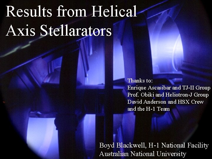
Results from Helical Axis Stellarators Thanks to: Enrique Ascasibar and TJ-II Group Prof. Obiki and Heliotron-J Group David Anderson and HSX Crew and the H-1 Team Boyd Blackwell, H-1 National Facility Australian National University
Outline Brief history Comparative parameters magnetic surfaces plasma formation and heating diagnostic issues Transport Stability fluctuations Acknowledgements: TJ-II, Heliotron-J, HSX and H-1 groups for their contributions and access to their data, in particular C. Alejaldre, E. Ascasibar, C. Hidalgo, T. Obiki, K. Nagasaki, D. T. Anderson, J. H. Harris, M. G. Shats, J. Howard, Nyima Gyaltsin, S. M. Collis and D. L. Rudakov.
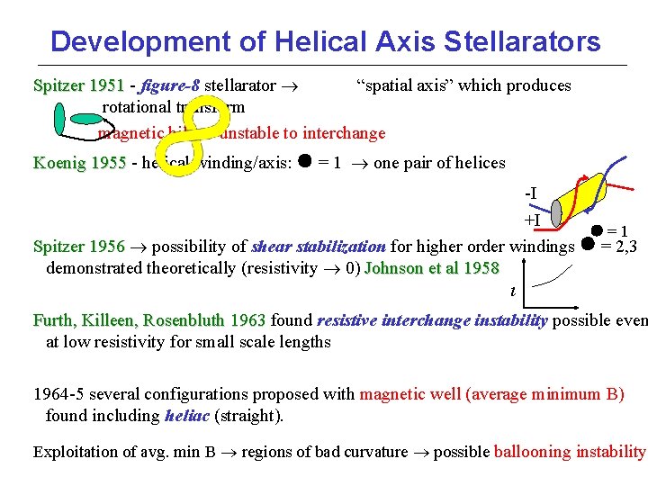
Development of Helical Axis Stellarators Spitzer 1951 - figure-8 stellarator “spatial axis” which produces Spitzer 1951 rotational transform magnetic hill unstable to interchange Koenig 1955 - helical winding/axis: = 1 one pair of helices 1955 -I +I = 1 Spitzer 1956 possibility of shear stabilization for higher order windings = 2, 3 Spitzer 1956 demonstrated theoretically (resistivity 0) Johnson et al 1958 Furth, Killeen, Rosenbluth 1963 found resistive interchange instability possible even 1963 at low resistivity for small scale lengths 1964 -5 several configurations proposed with magnetic well (average minimum B) found including heliac (straight). Exploitation of avg. min B regions of bad curvature possible ballooning instability
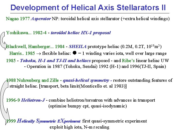
Development of Helical Axis Stellarators II Nagao 1977 Asperator NP: toroidal helical axis stellarator (+extra helical windings) Nagao 1977 Yoshikawa. . . 1982 -4 - toroidal heliac HX-1 proposal Yoshikawa. . . 1982 -4 19 m 3) Blackwell, Hamberger. . . 1984 - SHEILA prototype heliac (0. 2 M, 0. 2 T, 10. . . 1984 Harris. . 1985 flexible heliac: = 1 winding varies iota, well over large range 1985 - Tohoku, H-1 and TJ-II and heliacs proposed - and Ribe’s linear heliac UW 1985 Ribe’s - Operation in 1987 (Tohoku, Sendai) 1992 (H-1) and 1996(TJ-II, Spain) 1988 Nuhrenberg and Zille - quasi-helical symmetry - restore outstanding features of - straight heliac. [transport, beta limit(Monticello et. al 1983)] 1996 -9 Heliotron-J - combine heliotron/torsatron with advances in transport 1996 -9 (optimise bumpy cpt, quasi-isodynamic) 1999 Helically Symmetric EXperiment first quasi-symmetric experiment exploit high iota, N-m scaling
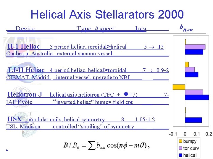
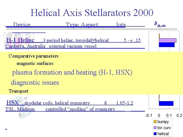
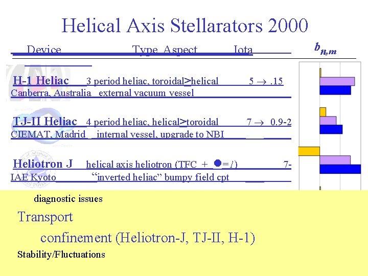
Helical Axis Stellarators 2000 Device Type Aspect b n, m Iota H-1 Heliac 3 period heliac, toroidal>helical Canberra, Australia external vacuum vessel 5 . 15 TJ-II Heliac 4 period heliac, helical>toroidal 7 0. 9 -2. 2 CIEMAT, Madrid internal vessel, upgrade to NBI Heliotron J IAE Kyoto helical axis heliotron (TFC + =1) “inverted heliac” bumpy field cpt 7 -11 0. 2 -0. 8 HSX modular coils, helical symmetry TSL, Madison. 8 1. 05 -1. 2 controlled “spoiling” of symmetry
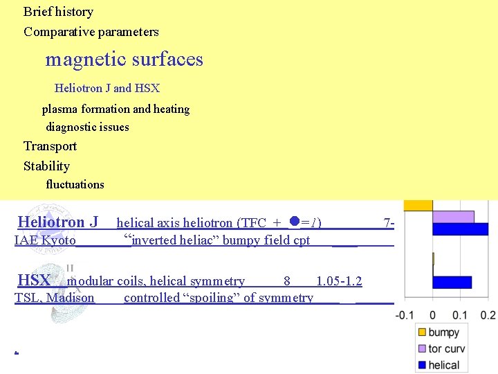
Brief history Comparative parameters Helical Axis Stellarators 2000 magnetic surfaces Device Type Aspect b n, m Iota Heliotron J and HSX plasma formation and heating H-1 Heliac 3 period heliac, toroidal>helical 5 . 15 Canberra, Australia external vacuum vessel diagnostic issues Transport TJ-II Heliac 4 period heliac, helical>toroidal 7 0. 9 -2. 2 Stability CIEMAT, Madrid internal vessel, upgrade to NBI fluctuations Heliotron J IAE Kyoto helical axis heliotron (TFC + =1) “inverted heliac” bumpy field cpt 7 -11 0. 2 -0. 8 HSX modular coils, helical symmetry TSL, Madison. 8 1. 05 -1. 2 controlled “spoiling” of symmetry
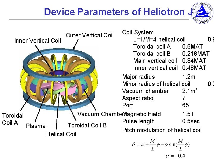
Device Parameters of Heliotron J Coil System L=1/M=4 helical coil 0. 9 Inner Vertical Coil Toroidal coil A 0. 6 MAT Toroidal coil B 0. 218 MAT Main vertical coil 0. 84 MAT Inner vertical coil 0. 48 MAT Major radius 1. 2 m Minor radius of helical coil 0. 2 Vacuum chamber 2. 1 m 3 Aspect ratio 7 Port 65 Magnetic Field 1. 5 T Vacuum Chamber Toroidal Pulse length 0. 5 sec Coil A Toroidal Coil B Plasma Pitch modulation of helical coil Helical Coil Outer Vertical Coil
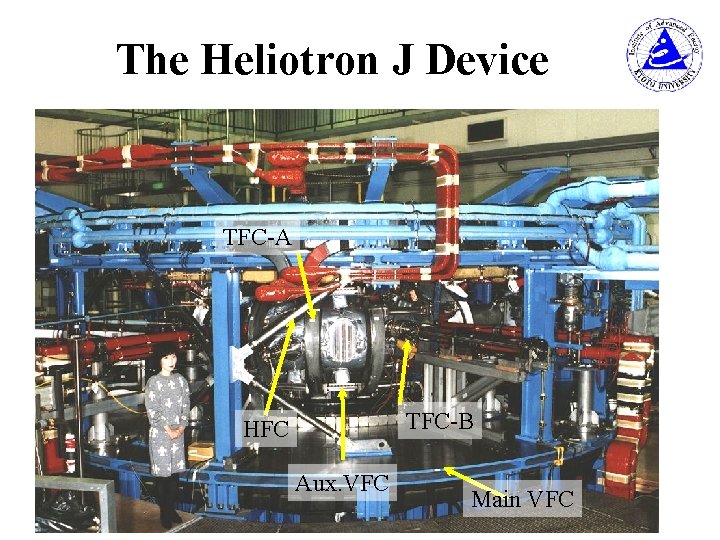
The Heliotron J Device TFC-A TFC-B HFC Aux. VFC Main VFC
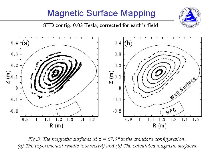
Magnetic Surface Mapping STD config, 0. 03 Tesla, corrected for earth’s field (a) (b) Fig. 3 The magnetic surfaces at = 67. 5 in the standard configuration. (a) The experimental results (corrected) and (b) The calculated magnetic surfaces.
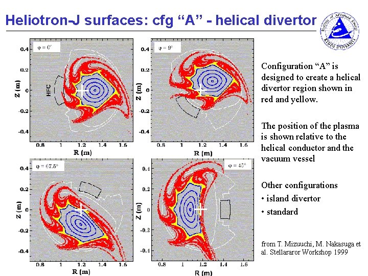
Heliotron-J surfaces: cfg “A” - helical divertor Configuration “A” is designed to create a helical divertor region shown in red and yellow. The position of the plasma is shown relative to the helical conductor and the vacuum vessel Other configurations • island divertor • standard from T. Mizuuchi, M. Nakasuga et al. Stellararor Workshop 1999
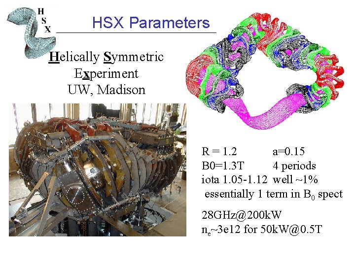
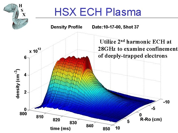
HSX Parameters Helically Symmetric Experiment UW, Madison R = 1. 2 a=0. 15 B 0=1. 3 T 4 periods iota 1. 05 -1. 12 well ~1% essentially 1 term in B 0 spect 28 GHz@200 k. W ne~3 e 12 for 50 k. W@0. 5 T
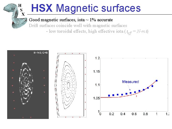
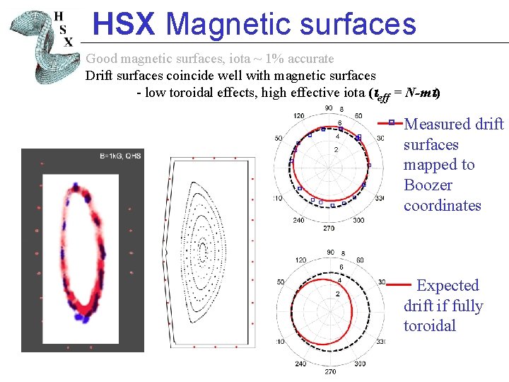
HSX Magnetic surfaces Good magnetic surfaces, iota ~ 1% accurate Drift surfaces coincide well with magnetic surfaces - low toroidal effects, high effective iota ( eff = N-m )
HSX Magnetic surfaces Good magnetic surfaces, iota ~ 1% accurate Drift surfaces coincide well with magnetic surfaces - low toroidal effects, high effective iota ( eff = N-m ) Measured drift surfaces mapped to Boozer coordinates Expected drift if fully toroidal
Helical Axis Stellarators 2000 Device Type Aspect H-1 Heliac 3 period heliac, toroidal>helical Canberra, Australia external vacuum vessel Iota b n, m 5 . 15 Comparative parameters TJ-II Heliac 4 period heliac, helical>toroidal 7 0. 9 -2. 2 magnetic surfaces CIEMAT, Madrid internal vessel, upgrade to NBI plasma formation and heating (H-1, HSX) Heliotron J helical axis heliotron (TFC + =1) 7 -11 0. 2 -0. 8 diagnostic issues IAE Kyoto “inverted heliac” bumpy field cpt Transport HSX modular coils, helical symmetry TSL, Madison. 8 1. 05 -1. 2 controlled “spoiling” of symmetry
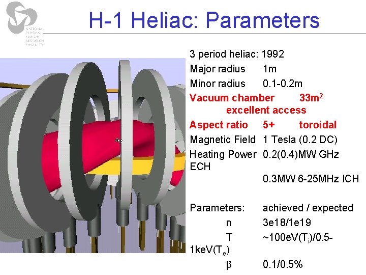
H-1 Heliac: Parameters 3 period heliac: 1992 Major radius 1 m Minor radius 0. 1 -0. 2 m Vacuum chamber 33 m 2 excellent access Aspect ratio 5+ toroidal Magnetic Field 1 Tesla (0. 2 DC) Heating Power 0. 2(0. 4)MW GHz ECH 0. 3 MW 6 -25 MHz ICH Parameters: n T 1 ke. V(Te) achieved / expected 3 e 18/1 e 19 ~100 e. V(Ti)/0. 50. 1/0. 5%
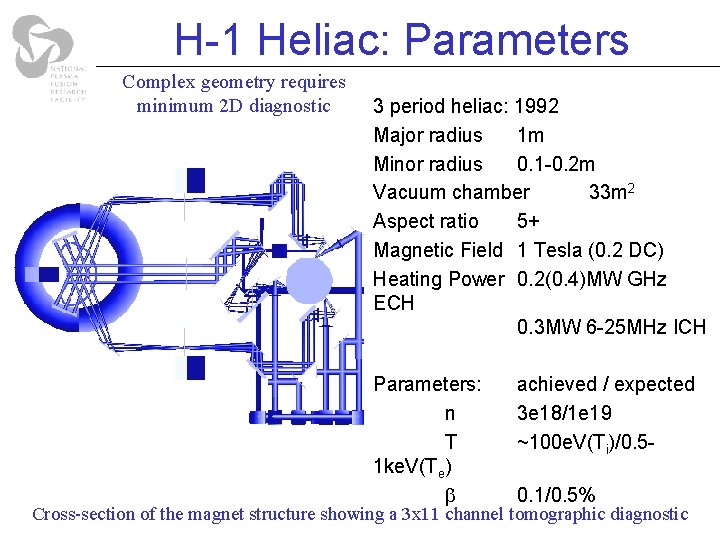
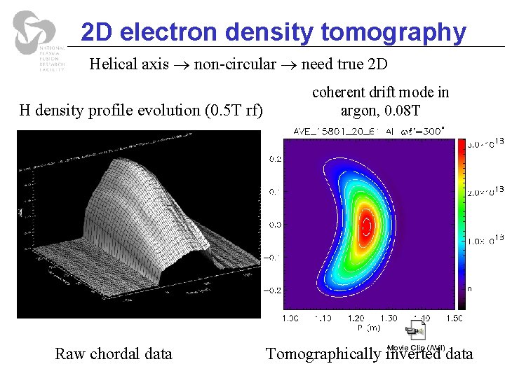
H-1 Heliac: Parameters Complex geometry requires minimum 2 D diagnostic 3 period heliac: 1992 Major radius 1 m Minor radius 0. 1 -0. 2 m Vacuum chamber 33 m 2 Aspect ratio 5+ Magnetic Field 1 Tesla (0. 2 DC) Heating Power 0. 2(0. 4)MW GHz ECH 0. 3 MW 6 -25 MHz ICH Parameters: n T 1 ke. V(Te) achieved / expected 3 e 18/1 e 19 ~100 e. V(Ti)/0. 50. 1/0. 5% Cross-section of the magnet structure showing a 3 x 11 channel tomographic diagnostic
2 D electron density tomography Helical axis non-circular need true 2 D H density profile evolution (0. 5 T rf) Raw chordal data coherent drift mode in argon, 0. 08 T Tomographically inverted data
HSX ECH Plasma Utilize 2 nd harmonic ECH at 28 GHz to examine confinement of deeply-trapped electrons
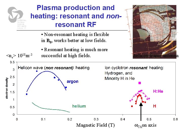
Plasma production and heating: resonant and nonresonant RF • Non-resonant heating is flexible in B 0, works better at low fields. <ne> 1018 m-3 • Resonant heating is much more successful at high fields. Magnetic Field (T) helicon/frame antenna = Chon axis
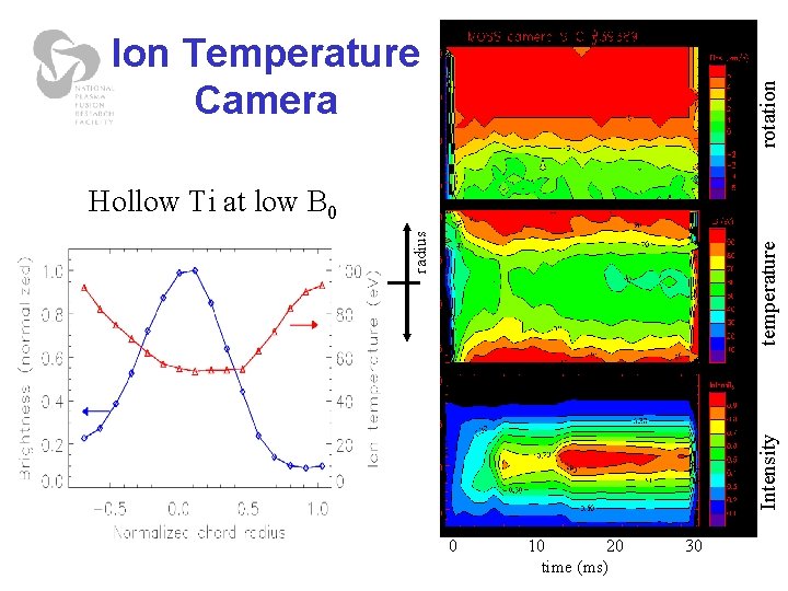
Hollow Ti at low B 0 Intensity temperature rotation radius Ion Temperature Camera 0 10 20 time (ms) 30
Helical Axis Stellarators 2000 Device Type Aspect bn, m Iota H-1 Heliac 3 period heliac, toroidal>helical Canberra, Australia external vacuum vessel 5 . 15 TJ-II Heliac 4 period heliac, helical>toroidal 7 0. 9 -2. 2 CIEMAT, Madrid internal vessel, upgrade to NBI Heliotron J IAE Kyoto helical axis heliotron (TFC + =1) “inverted heliac” bumpy field cpt diagnostic issues HSX modular coils, helical symmetry 8 1. 05 -1. 2 Transport controlled “spoiling” of symmetry TSL, Madison confinement (Heliotron-J, TJ-II, H-1). Stability/Fluctuations 7 -11 0. 2 -0. 8
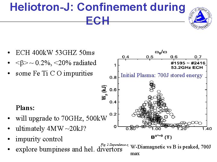
Heliotron-J: Confinement during ECH • ECH 400 k. W 53 GHZ 50 ms • < > ~ 0. 2%, <20% radiated • some Fe Ti C O impurities • • Initial Plasma: 700 J stored energy Plans: will upgrade to 70 GHz, 500 k. W ultimately 4 MW ~20 k. J? impurity control Fig. 2 Dependence of the diamagnetic stored energy on the magnetic field strength. explore bumpiness and hel. divertors W-Diamagnetic vs B is peaked, 700 J max
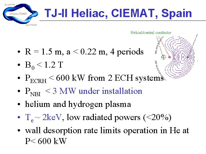
TJ-II Heliac, CIEMAT, Spain Helical/central conductor • • R = 1. 5 m, a < 0. 22 m, 4 periods B 0 < 1. 2 T PECRH < 600 k. W from 2 ECH systems PNBI < 3 MW under installation helium and hydrogen plasma Te ~ 2 ke. V, low radiated powers (<20%) wall desorption rate limits operation in He at P< 600 k. W
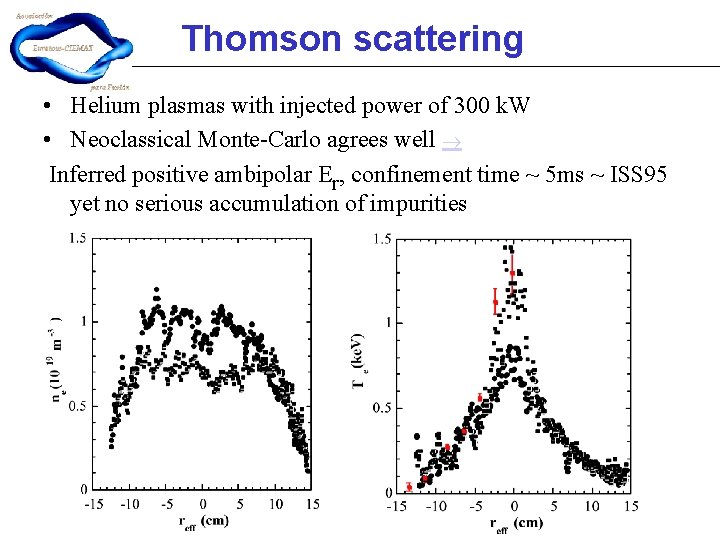
Thomson scattering • Helium plasmas with injected power of 300 k. W • Neoclassical Monte-Carlo agrees well Inferred positive ambipolar Er, confinement time ~ 5 ms ~ ISS 95 yet no serious accumulation of impurities
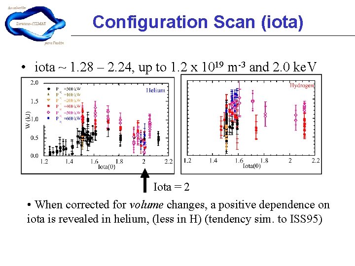
Configuration Scan (iota) • iota ~ 1. 28 – 2. 24, up to 1. 2 x 10¹⁹ m-3 and 2. 0 ke. V Iota = 2 • When corrected for volume changes, a positive dependence on iota is revealed in helium, (less in H) (tendency sim. to ISS 95)
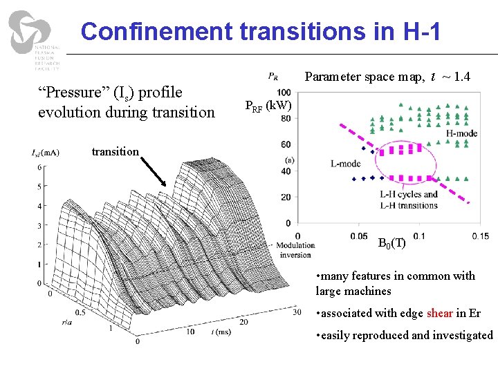
Confinement transitions in H-1 “Pressure” (Is) profile evolution during transition Parameter space map, ~ 1. 4 PRF (k. W) transition B 0(T) • many features in common with large machines • associated with edge shear in Er • easily reproduced and investigated
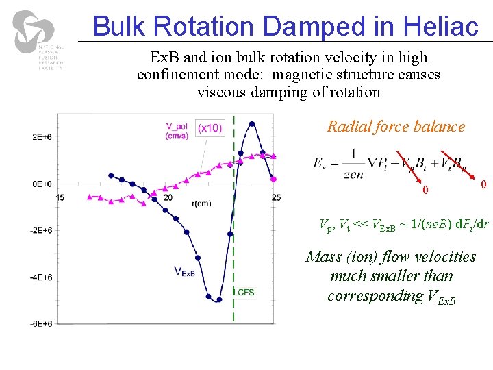
Bulk Rotation Damped in Heliac Ex. B and ion bulk rotation velocity in high confinement mode: magnetic structure causes viscous damping of rotation Radial force balance 0 0 Vp, Vt << VEx. B ~ 1/(ne. B) d. Pi/dr Mass (ion) flow velocities much smaller than corresponding VEx. B
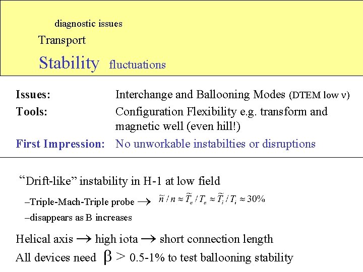
diagnostic issues Transport Stability fluctuations Issues: Tools: Interchange and Ballooning Modes (DTEM low ) Configuration Flexibility e. g. transform and magnetic well (even hill!) First Impression: No unworkable instabilties or disruptions “Drift-like” instability in H-1 at low field –Triple-Mach-Triple probe –disappears as B increases Helical axis high iota short connection length All devices need > 0. 5 -1% to test ballooning stability
TJ-II Turbulence/Fluctuation studies • Ex. B sheared flows observed near edge rational surfaces (8/5, 4/2) • Spectra mainly <200 k. Hz, 10 -40% (edge? ), correlation time 10 ms • MHD (ELM-like) events (for W~1 k. J) - magnetic activity - spike in the Ha signal. • Fluctuations increase with magnetic hill near edge • resistive ballooning?
Summary - Future • • • Confinement in heliacs ~ISS 95 or better (2 ke. V, ~5 ms). Ion beam probe to elucidate role of Eradial in improved confinement New configurations with improved neoclassical transport initial results promising, await mature data, analysis HSX/H-J can compare similar configurations with vastly different neoclassical transport predictions. Confinement transitions possible at low power, many similarities with large devices/powers. Investigate effect of E-field imposed by localised ECH. No serious impurity accumulation problems yet. Real test when the ions are strongly heated No fatal instabilities observed yet. Several devices should have the heating capacity to test ballooning limits, at least in degraded configurations (consequence of flexibility).