
RESOLVING TRANSFORMER NOISE AND ELECTRICAL HARMONICS PROBLEMS ASSOCIATED
RESOLVING TRANSFORMER NOISE AND ELECTRICAL HARMONICS PROBLEMS ASSOCIATED WITH DEEP WELL PUMPING SYSTEMS Craig Patterson, Project Engineer, Meurer & Associates Paul D. Goldfain, Associate Principal, Meurer & Associates Robert Anderson, Electrical Engineer, The RMH Group David Kaunisto, District Manager, East Cherry Creek Valley Water & Sanitation District 1
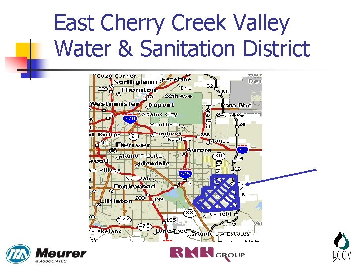
East Cherry Creek Valley Water & Sanitation District 2
East Cherry Creek Valley Water & Sanitation District n § § Approximately 50, 000 population 10 -15 MGD yearly range Water Supply – Arapahoe aquifer (1, 500’ - 1, 800’ deep) – Laramie-Fox Hills aquifer (1, 800’ – 2, 300’ deep) 3

Deep Well Installation Diagram 480 Volts UTILITY TRANSFORMER (XFMR) 480 Volts VARIABLE FREQUENCY DRIVE (VFD) 2300 Volts STEP-UP TRANSFORMER SUBMERSIBLE WELL PUMP AND MOTOR 4
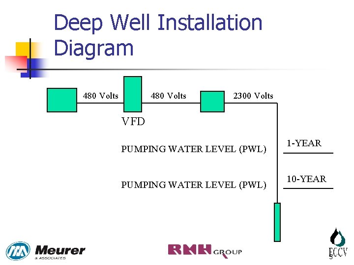
Deep Well Installation Diagram 480 Volts 2300 Volts VFD PUMPING WATER LEVEL (PWL) 1 -YEAR 10 -YEAR 5
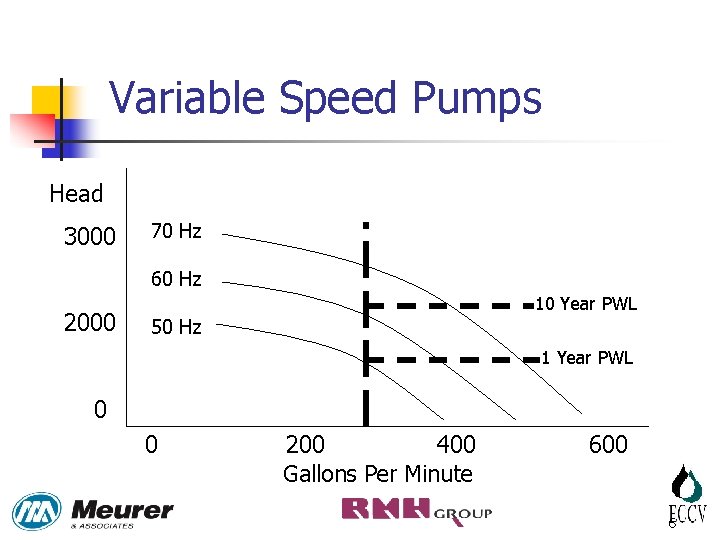
Variable Speed Pumps Head 3000 70 Hz 60 Hz 2000 10 Year PWL 50 Hz 1 Year PWL 0 0 200 400 Gallons Per Minute 600 6
Discussion of Problem – Power Factor n Power Factor is the percentage difference between apparent and actual power. § The Electric utility requires at least 95%. § P. S. SA-8 was 84%. 7
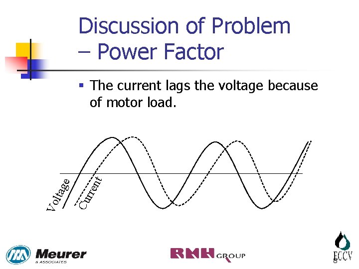
Discussion of Problem – Power Factor nt rre Cu Vo ltag e § The current lags the voltage because of motor load. 8
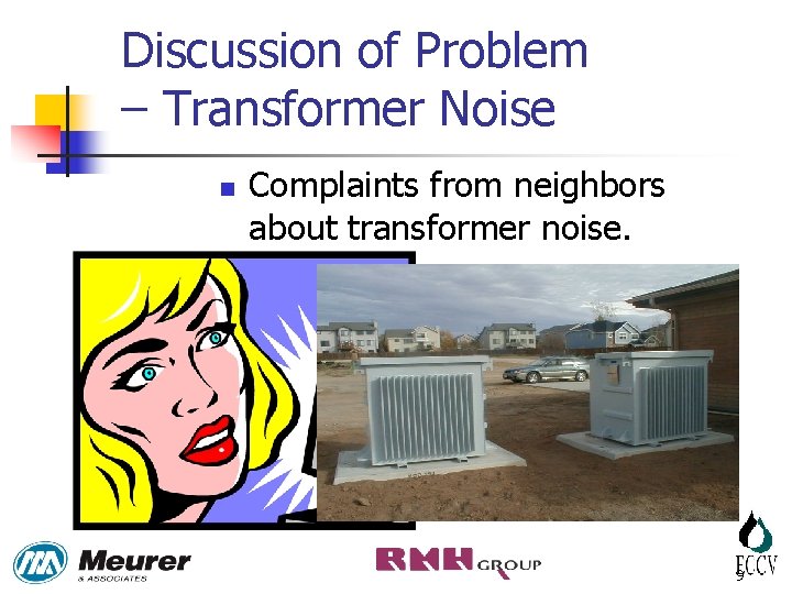
Discussion of Problem – Transformer Noise n Complaints from neighbors about transformer noise. 9
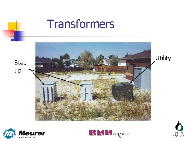
Transformers Stepup Utility 10
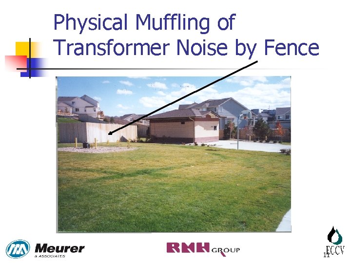
Physical Muffling of Transformer Noise by Fence 11
Goal Equipment combination that will: §Provide adequate power factor §Reduce noise to acceptable level §Provide operating flexibility to meet varying demands. 12
Electrical Analysis n n RMH Group analyzed the power systems at several pump stations. They determined that problem was caused by voltage and current harmonics generated in the VFDs. 13
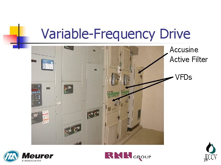
Variable-Frequency Drive Accusine Active Filter VFDs 14
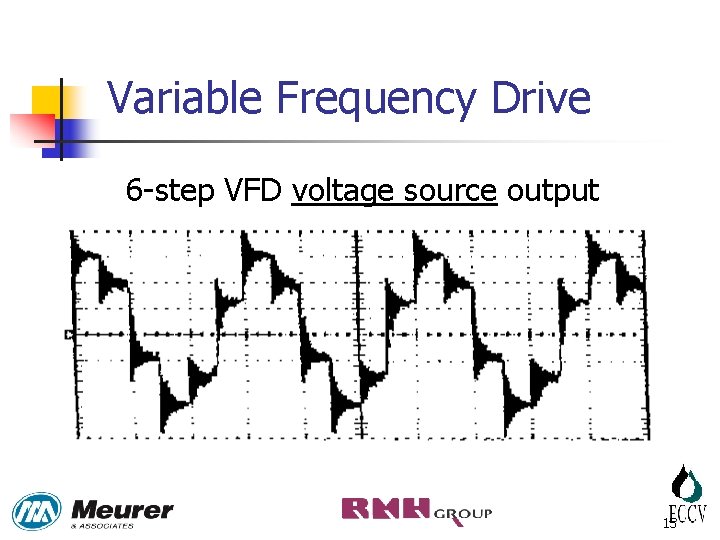
Variable Frequency Drive 6 -step VFD voltage source output 15
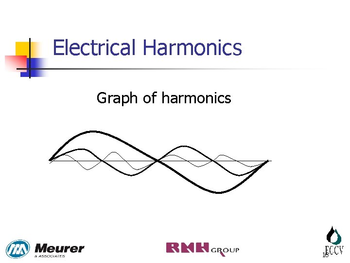
Electrical Harmonics Graph of harmonics 16
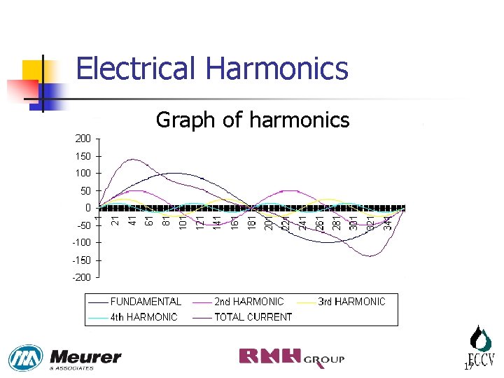
Electrical Harmonics Graph of harmonics 17
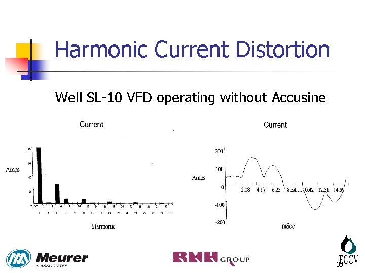
Harmonic Current Distortion Well SL-10 VFD operating without Accusine 18
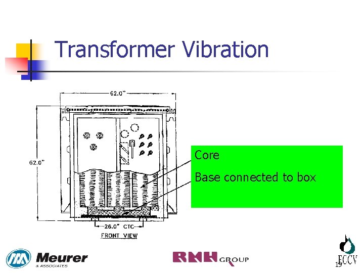
Transformer Vibration Core Base connected to box 19
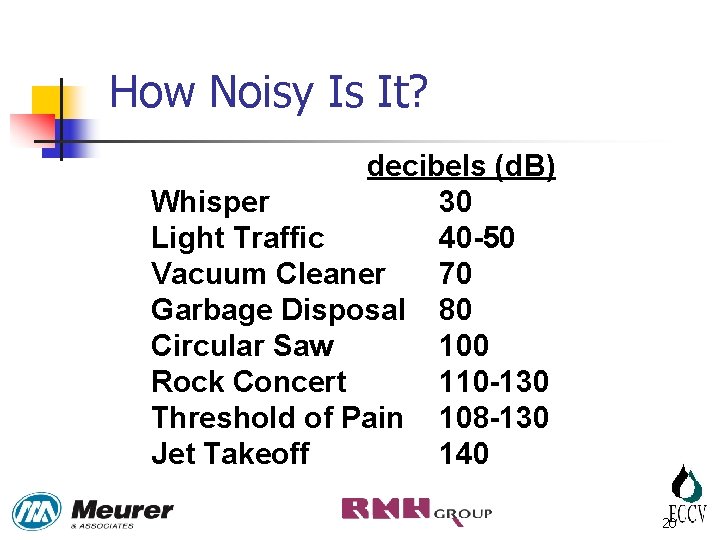
How Noisy Is It? decibels (d. B) Whisper 30 Light Traffic 40 -50 Vacuum Cleaner 70 Garbage Disposal 80 Circular Saw 100 Rock Concert 110 -130 Threshold of Pain 108 -130 Jet Takeoff 140 20
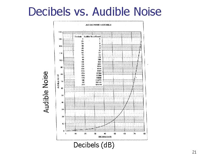
Audible Noise Decibels vs. Audible Noise Decibels (d. B) 21
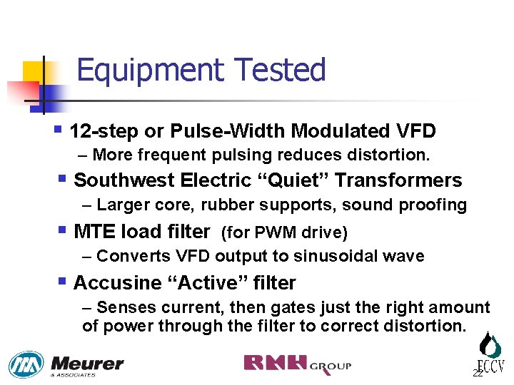
Equipment Tested § 12 -step or Pulse-Width Modulated VFD – More frequent pulsing reduces distortion. § Southwest Electric “Quiet” Transformers – Larger core, rubber supports, sound proofing § MTE load filter (for PWM drive) – Converts VFD output to sinusoidal wave § Accusine “Active” filter – Senses current, then gates just the right amount of power through the filter to correct distortion. 22
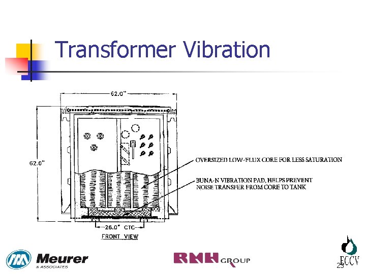
Transformer Vibration 23
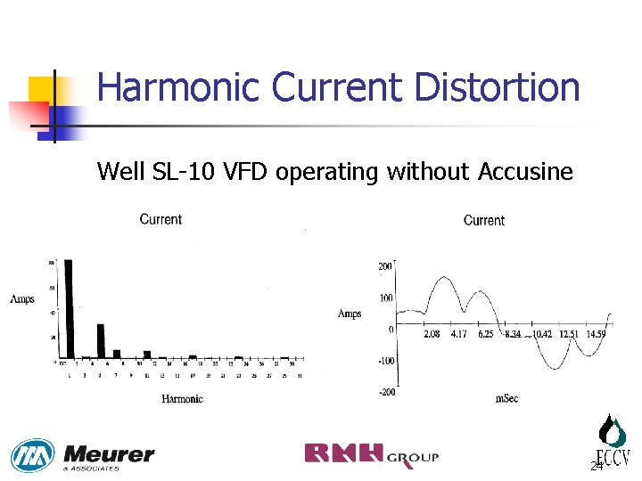
Harmonic Current Distortion Well SL-10 VFD operating without Accusine 24
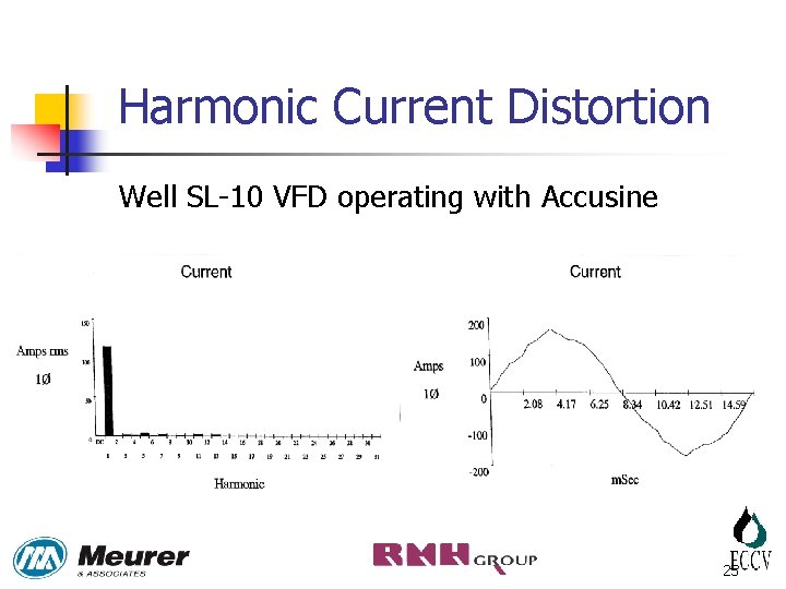
Harmonic Current Distortion Well SL-10 VFD operating with Accusine 25
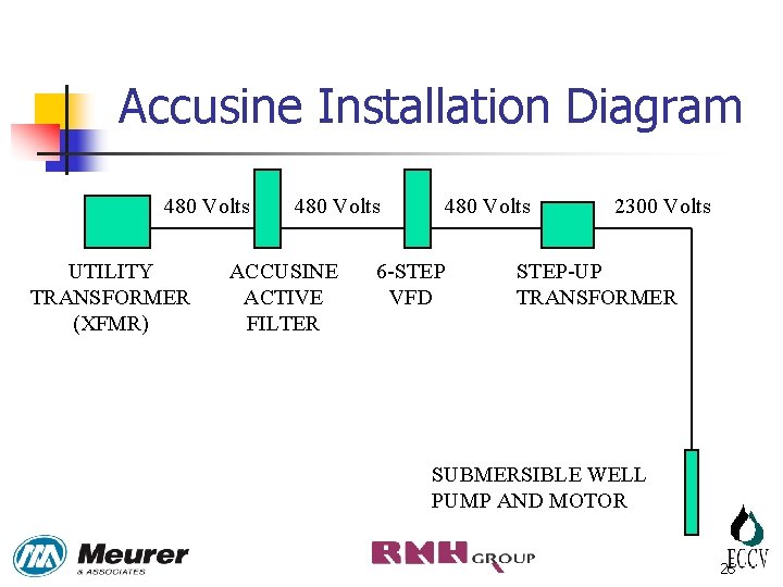
Accusine Installation Diagram 480 Volts UTILITY TRANSFORMER (XFMR) 480 Volts ACCUSINE ACTIVE FILTER 480 Volts 6 -STEP VFD 2300 Volts STEP-UP TRANSFORMER SUBMERSIBLE WELL PUMP AND MOTOR 26
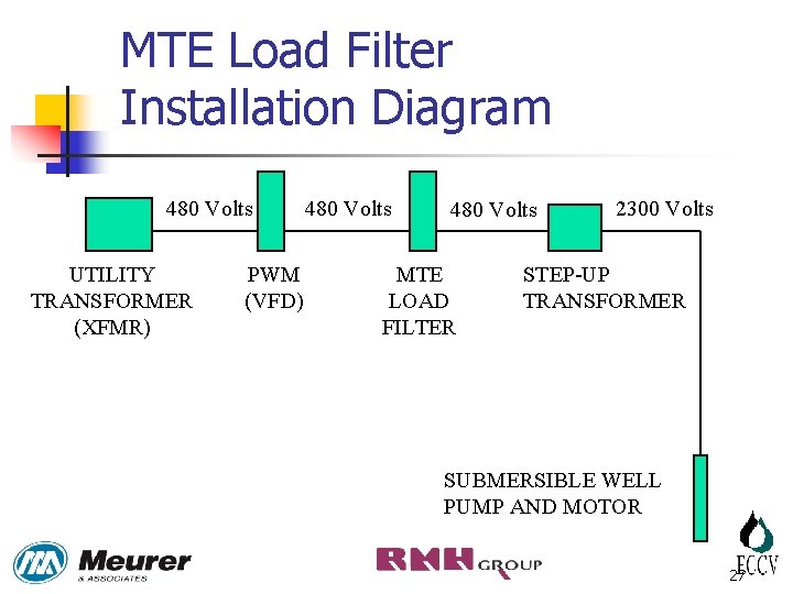
MTE Load Filter Installation Diagram 480 Volts UTILITY TRANSFORMER (XFMR) PWM (VFD) 480 Volts MTE LOAD FILTER 2300 Volts STEP-UP TRANSFORMER SUBMERSIBLE WELL PUMP AND MOTOR 27
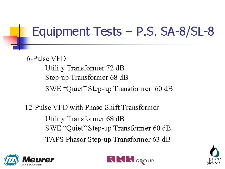
Equipment Tests – P. S. SA-8/SL-8 6 -Pulse VFD Utility Transformer 72 d. B Step-up Transformer 68 d. B SWE “Quiet” Step-up Transformer 60 d. B 12 -Pulse VFD with Phase-Shift Transformer Utility Transformer 68 d. B SWE “Quiet” Step-up Transformer 60 d. B TAPS Phasor Step-up Transformer 63 d. B 28
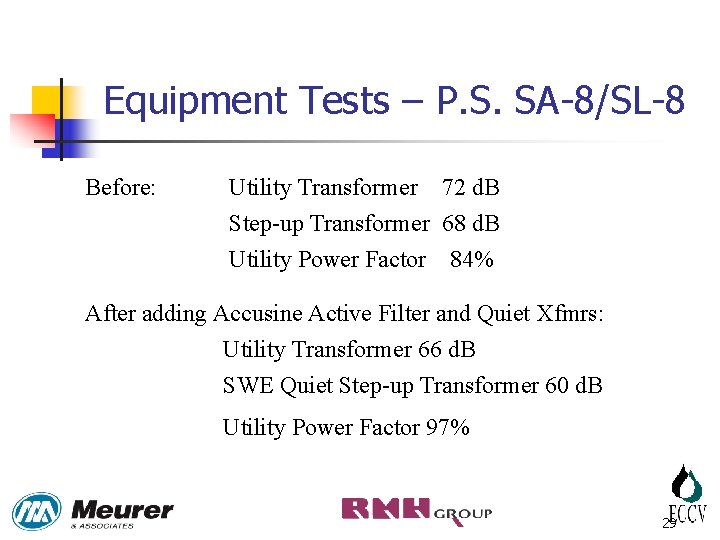
Equipment Tests – P. S. SA-8/SL-8 Before: Utility Transformer 72 d. B Step-up Transformer 68 d. B Utility Power Factor 84% After adding Accusine Active Filter and Quiet Xfmrs: Utility Transformer 66 d. B SWE Quiet Step-up Transformer 60 d. B Utility Power Factor 97% 29
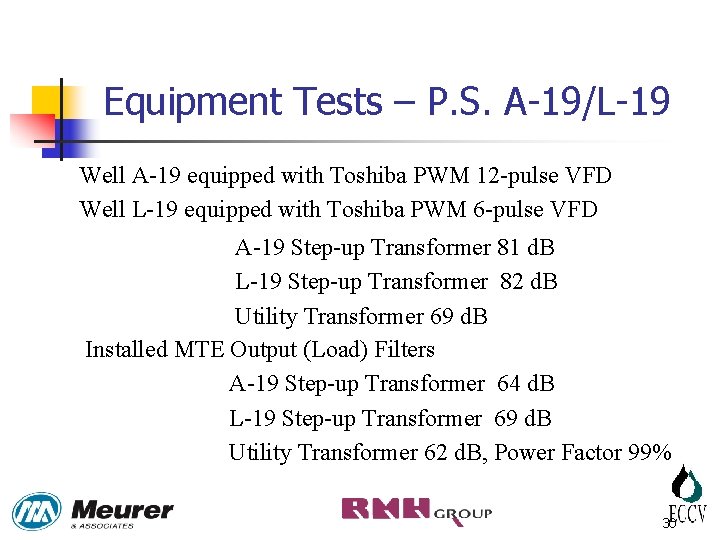
Equipment Tests – P. S. A-19/L-19 Well A-19 equipped with Toshiba PWM 12 -pulse VFD Well L-19 equipped with Toshiba PWM 6 -pulse VFD A-19 Step-up Transformer 81 d. B L-19 Step-up Transformer 82 d. B Utility Transformer 69 d. B Installed MTE Output (Load) Filters A-19 Step-up Transformer 64 d. B L-19 Step-up Transformer 69 d. B Utility Transformer 62 d. B, Power Factor 99% 30
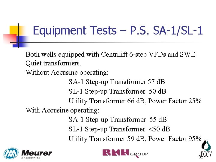
Equipment Tests – P. S. SA-1/SL-1 Both wells equipped with Centrilift 6 -step VFDs and SWE Quiet transformers. Without Accusine operating: SA-1 Step-up Transformer 57 d. B SL-1 Step-up Transformer 50 d. B Utility Transformer 66 d. B, Power Factor 25% With Accusine operating: SA-1 Step-up Transformer 55 d. B SL-1 Step-up Transformer <50 d. B Utility Transformer 59 d. B, Power Factor 95% 31
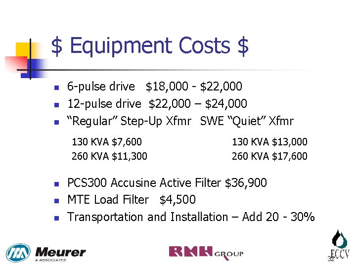
$ Equipment Costs $ n n n 6 -pulse drive $18, 000 - $22, 000 12 -pulse drive $22, 000 – $24, 000 “Regular” Step-Up Xfmr SWE “Quiet” Xfmr 130 KVA $7, 600 260 KVA $11, 300 n n n 130 KVA $13, 000 260 KVA $17, 600 PCS 300 Accusine Active Filter $36, 900 MTE Load Filter $4, 500 Transportation and Installation – Add 20 - 30% 32
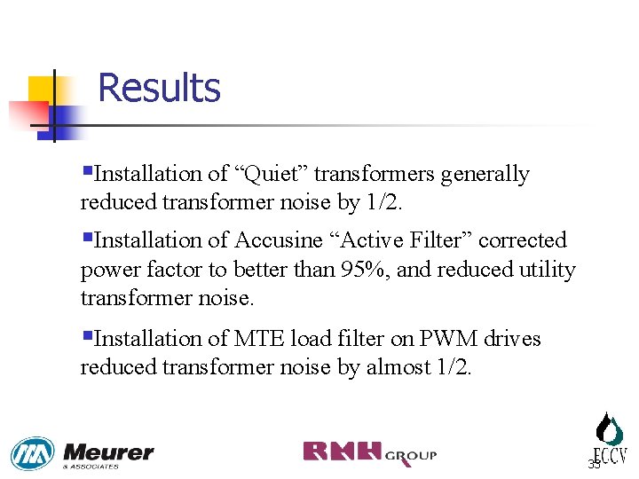
Results §Installation of “Quiet” transformers generally reduced transformer noise by 1/2. §Installation of Accusine “Active Filter” corrected power factor to better than 95%, and reduced utility transformer noise. §Installation of MTE load filter on PWM drives reduced transformer noise by almost 1/2. 33
Questions? Craig Patterson, Project Engineer, Meurer & Associates Paul D. Goldfain, Associate Principal, Meurer & Associates Robert Anderson, Electrical Engineer, The RMH Group David Kaunisto, District Manager, East Cherry Creek Valley Water & Sanitation District 34
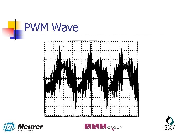
PWM Wave 35
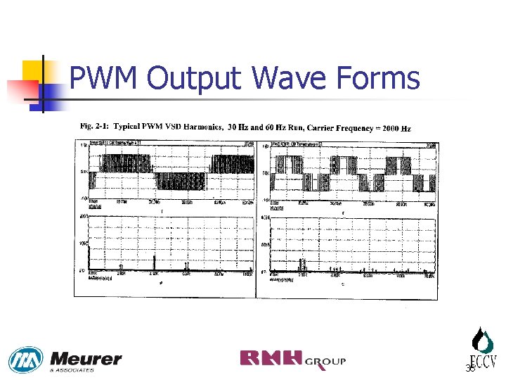
PWM Output Wave Forms 36
- Slides: 36