Resistance Chapter 23 Define Resistance The Resistance of


, at constant temperature, the")


 as shown. By moving")


- Slides: 34
Resistance Chapter 23
Define Resistance. The Resistance of a conductor is the ratio of the potential difference across it to the current flowing through it. R is resistance V is voltage I is current
What is the SI unit of Resistance? The SI unit of resistance is the ohm (Ω). Define the ohm. A conductor has a resistance of 1 Ω if the current through it is 1 A when the pd across it is 1 V.
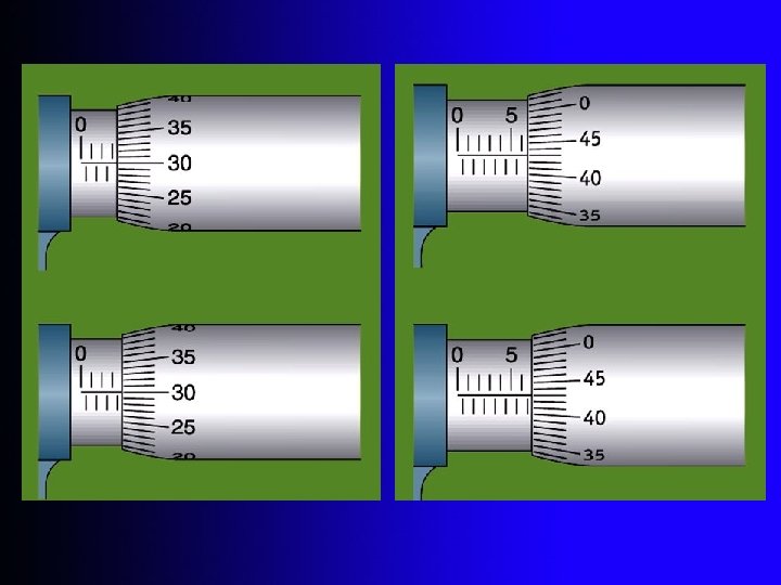
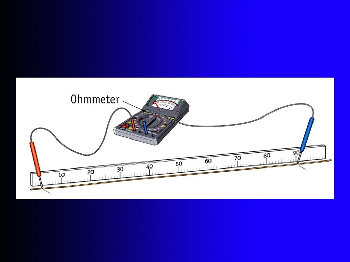
Measuring Resistance An ohmmeter can be used to measure resistance. By selecting one of its resistance scales a digital multimeter reads the resistance of whatever is connected across the ends of its probes. A Metre bridge, a Wheatstone bridge or an Ammeter and Voltmeter can also be used to measure resistance.
State Ohm’s Law states that for certain conductors (mainly metals), at constant temperature, the Current is directly proportional to the Voltage. I is the Current V is the Voltage
Ohm’s Law A graph of current against voltage is plotted for a conductor that obeys Ohm’s Law. Describe the shape of the graph. Since the current is directly proportional to the voltage the graph is: • a straight line • passing through the origin.
Ohm’s Law. If a conductor obeys Ohm’s Law then: as the voltage V across it varies so does the current I that flows through it. However, the ratio of V to I remains the same value. Put another way, as the voltage and current vary the resistance remains the same.
Electrical Circuit Symbols
Resistors in Series The diagram shows three Resistors in Series. Give an expression for the effective resistance of the three. R = R 1 + R 2 + R 3
Resistors in Parallel The diagram shows three Resistors in Parallel. Give an expression for the effective resistance of the three.
A Variable Resistor Current flows through the variable resistor (rheostat) as shown. By moving the sliding contact along the bar we can cause the current to pass through all of the wire, some of the wire or none of the wire in the coil thus changing the total resistance of the circuit in which it is connected.
A Potentiometer Another type of variable resistor, called a Potentiometer, is shown below. Potentiometers are often found in radios usually controlling volume. It operates similarly to the rheostat except that the current flows along a carbon track rather than a coil of wire.
Find the current flowing through each resistor in the circuit shown. (Answers: 2 A, 3 A and 5 A)
The Resistance of a Conductor depends on: Its Length Its Cross-sectional area The material from which it is made Its Temperature
The Length doubles and the Resistance doubles.
Resistance and Length The Resistance of a uniform conductor is directly proportional to its Length. For a fixed cross-sectional Area A.
The Cross-sectional Area is doubled and the Resistance is halved.
Resistance and Cross-sectional Area The Resistance of a uniform conductor is Inversely Proportional to its Cross-sectional Area. For a fixed length l.
What is Resistivity? If a conductor of length l and cross-sectional area A has a resistance R, then the constant ρ given by: is its Resistivity.
What is the SI Unit of Resistivity? The SI Unit of Resistivity is the ohm metre (Ω m).
Variation of the Resistance of a Metallic Conductor with Temperature The graph shows how the resistance of a metallic conductor varies with temperature. The graph is a straight line, but it does not pass through the origin. We say the resistance changes linearly with temperature. The increase in resistance is not very great, for moderate increases in temperature.
Explain why the resistance of a metallic conductor increases as the temperature increases. As the temperature of the metal increases the metal atoms vibrate at a greater rate. The electrons, in trying to move through the metal, collide more frequently with the atoms. The electrons therefore meet increased resistance. i. e. the resistance of a metallic conductor increases as the temperature increases.
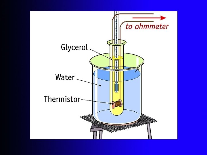
Variation of the Resistance of a Thermistor with Temperature The graph shows how the resistance of a thermistor varies with temperature. The resistance of thermistor decreases dramatically as the temperature increases.
Explain why the resistance of a thermistor decreases as the temperature increases. As the temperature of thermistor increases, more electrons break free from their bonds. There are thus more charge carriers available for conduction. Thus the resistance decreases.
The Wheatstone Bridge shown is said to be Balanced when the Galvanometer reads Zero.
Wheatstone Bridge formula When the Wheatstone Bridge is balanced:
A Metre Bridge A simple and easy to use form of the Wheatstone Bridge is the Metre Bridge. When the bridge is balanced:
Calculate the pd across each resistor in the diagram. Answer: V 1 = 4 V and V 2 = 8 V Calculate the pd across each resistor in the diagram. Answer: V 1 = 11. 98 V V 2 = 0. 02395 V and
A Potential Divider Circuit If two resistors are connected in series across a fixed voltage supply: The greater voltage is across the greater resistor. The sum of the voltages is the supply voltage. The resistors divide the pd of the supply in the ratio of their resistances. The circuit is called a Potential Divider Circuit.
A variable Potential Divider circuit A Variable Potential Divider provides any voltage from zero volts to the supply voltage by sliding a movable contact. As the movable contact is moved from A to B the output voltage increases from zero volts (at A) to 12 volts (at B)