
Resident Physics Lectures Christensen Chapter 2 B Tube
Resident Physics Lectures • Christensen, Chapter 2 B Tube Ratings George David Associate Professor Department of Radiology Medical College of Georgia
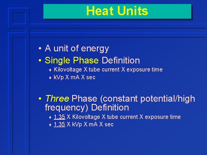
Heat Units • A unit of energy • Single Phase Definition ¨ Kilovoltage X tube current X exposure time ¨ k. Vp X m. A X sec • Three Phase (constant potential/high frequency) Definition ¨ 1. 35 X Kilovoltage X tube current X exposure time ¨ 1. 35 X k. Vp X m. A X sec
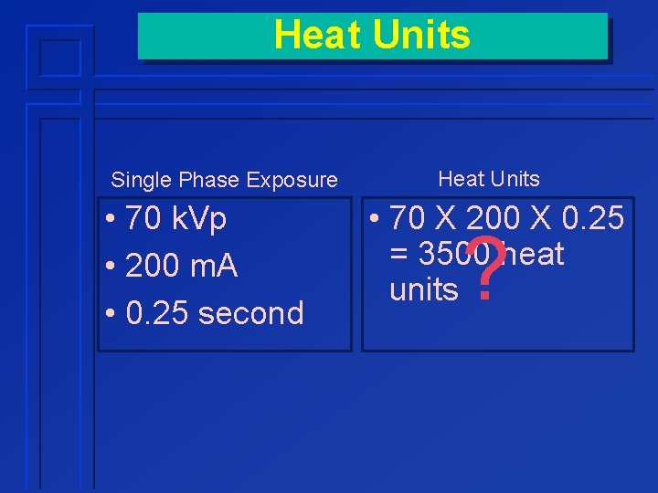
Heat Units Single Phase Exposure • 70 k. Vp • 200 m. A • 0. 25 second Heat Units • 70 X 200 X 0. 25 = 3500 heat units ?
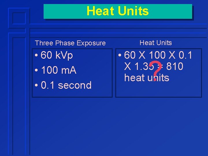
Heat Units Three Phase Exposure • 60 k. Vp • 100 m. A • 0. 1 second Heat Units • 60 X 100 X 0. 1 X 1. 35 = 810 heat units ?
Heat is the Enemy X-Ray Tube Heat
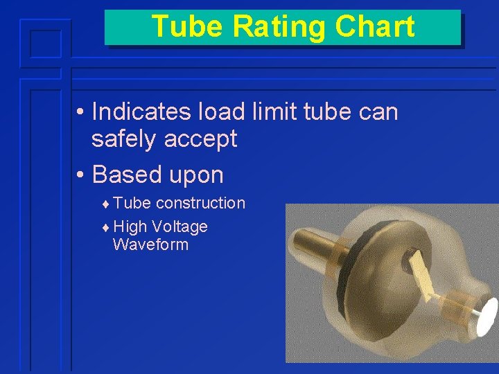
Tube Rating Chart • Indicates load limit tube can safely accept • Based upon ¨ Tube construction ¨ High Voltage Waveform
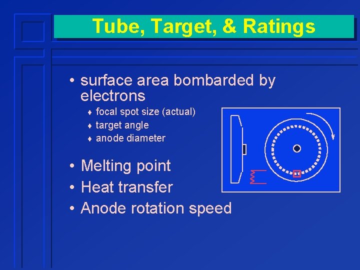
Tube, Target, & Ratings • surface area bombarded by electrons ¨ focal spot size (actual) ¨ target angle ¨ anode diameter • Melting point • Heat transfer • Anode rotation speed
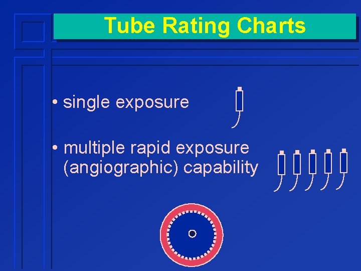
Tube Rating Charts • single exposure • multiple rapid exposure (angiographic) capability
Single Exposure Rating Charts • Tube specific • Incorporated in virtually all generators ¨ prevents illegal single exposures • Better ratings (more heat allowed) for ¨ Large focal spot ¨ High speed anode rotation
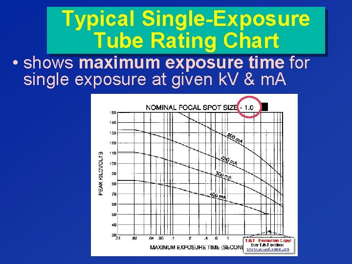
Typical Single-Exposure Tube Rating Chart • shows maximum exposure time for single exposure at given k. V & m. A
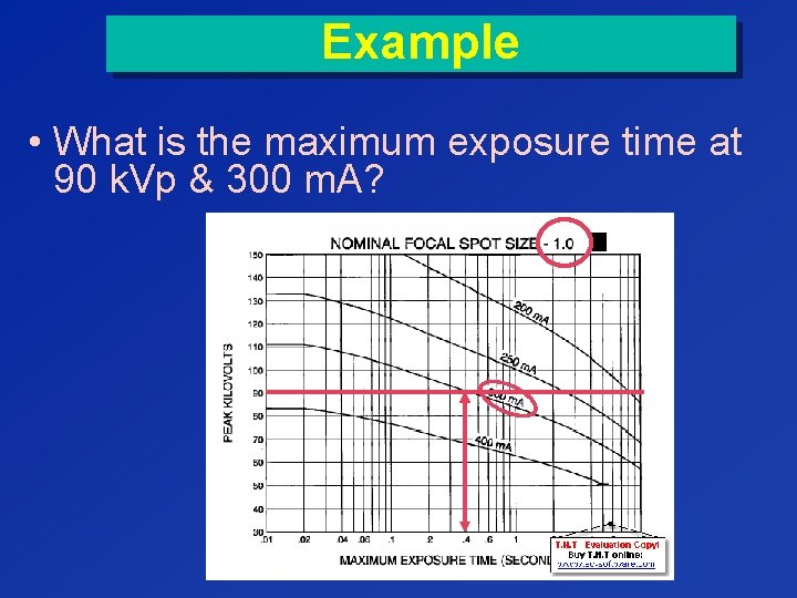
Example • What is the maximum exposure time at 90 k. Vp & 300 m. A?
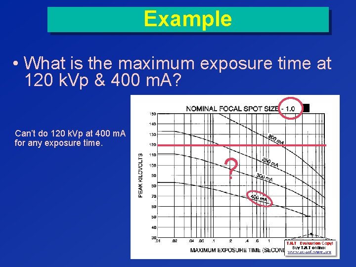
Example • What is the maximum exposure time at 120 k. Vp & 400 m. A? Can’t do 120 k. Vp at 400 m. A for any exposure time. ?
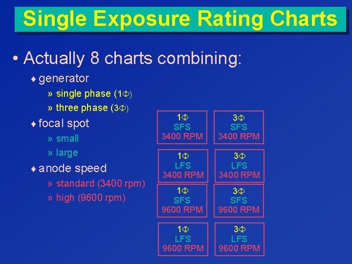
Single Exposure Rating Charts • Actually 8 charts combining: ¨ generator » single phase (1 F) » three phase (3 F) ¨ focal spot » small » large ¨ anode speed » standard (3400 rpm) » high (9600 rpm) 1 F SFS 3400 RPM 3 F SFS 3400 RPM 1 F LFS 3400 RPM 3 F LFS 3400 RPM 1 F SFS 9600 RPM 3 F SFS 9600 RPM 1 F LFS 9600 RPM 3 F LFS 9600 RPM
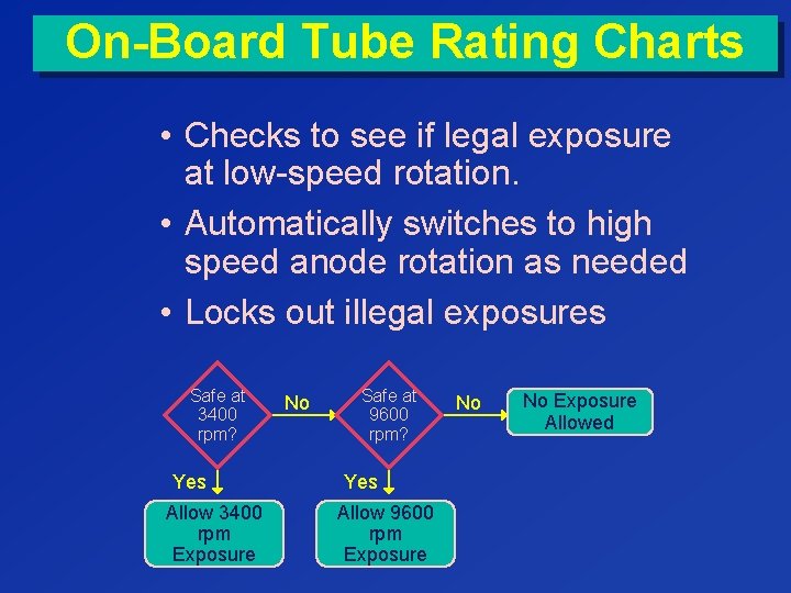
On-Board Tube Rating Charts • Checks to see if legal exposure at low-speed rotation. • Automatically switches to high speed anode rotation as needed • Locks out illegal exposures Safe at 3400 rpm? Yes Allow 3400 rpm Exposure No Safe at 9600 rpm? Yes Allow 9600 rpm Exposure No No Exposure Allowed
Kilowatt Rating • Ability of x-ray tube to make single exposure of reasonable duration (usually. 1 sec. ) • Found on tube rating chart ¨ standard assumptions » Use 0. 1 sec. exposure time » Three phase chart » high speed rotor rotation
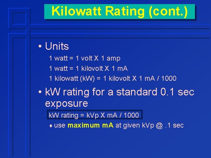
Kilowatt Rating (cont. ) • Units 1 watt = 1 volt X 1 amp 1 watt = 1 kilovolt X 1 m. A 1 kilowatt (k. W) = 1 kilovolt X 1 m. A / 1000 • k. W rating for a standard 0. 1 sec exposure k. W rating = k. Vp X m. A / 1000 ¨ use maximum m. A at given k. Vp @. 1 sec
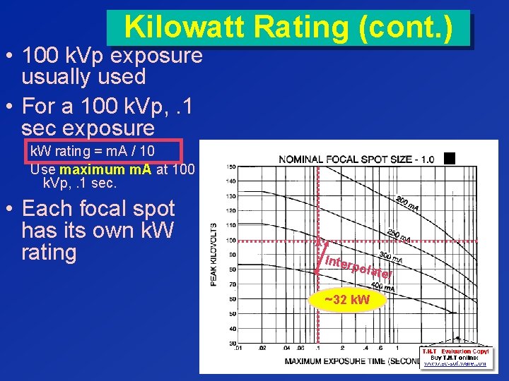
Kilowatt Rating (cont. ) • 100 k. Vp exposure usually used • For a 100 k. Vp, . 1 sec exposure k. W rating = m. A / 10 Use maximum m. A at 100 k. Vp, . 1 sec. • Each focal spot has its own k. W rating X Inter polat e ~32 k. W !
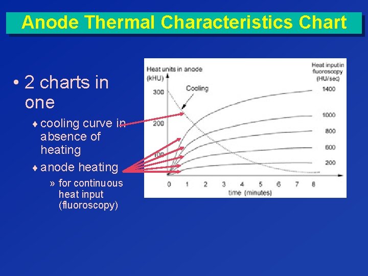
Anode Thermal Characteristics Chart • 2 charts in one ¨ cooling curve in absence of heating ¨ anode heating » for continuous heat input (fluoroscopy)
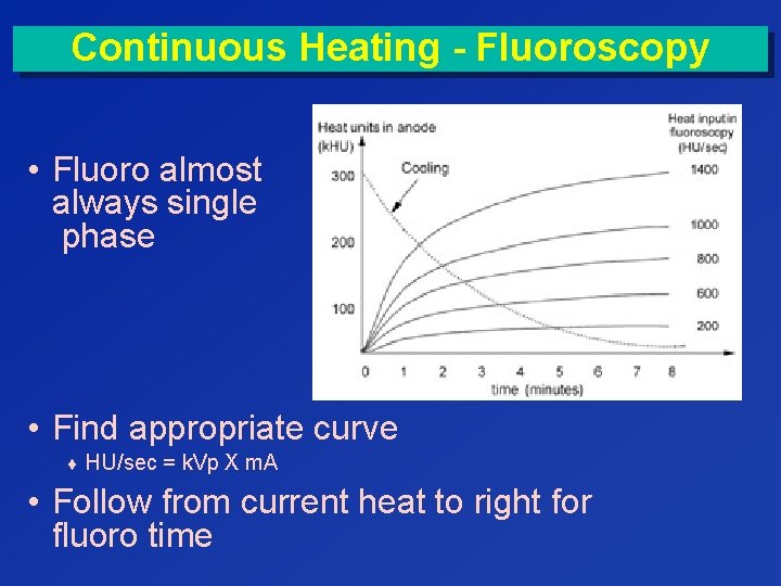
Continuous Heating - Fluoroscopy • Fluoro almost always single phase • Find appropriate curve ¨ HU/sec = k. Vp X m. A • Follow from current heat to right for fluoro time
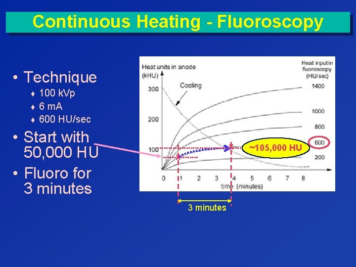
Continuous Heating - Fluoroscopy • Technique ¨ 100 k. Vp ¨ 6 m. A ¨ 600 HU/sec • Start with 50, 000 HU • Fluoro for 3 minutes x x 3 minutes ~105, 000 HU
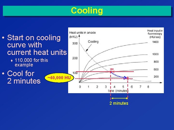
Cooling • Start on cooling curve with current heat units ¨ 110, 000 for this example • Cool for 2 minutes xx ~40, 000 HU x 2 minutes
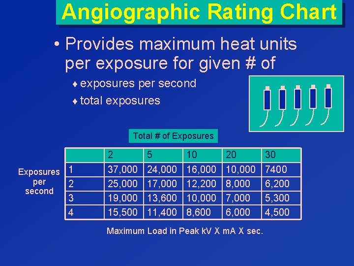
Angiographic Rating Chart • Provides maximum heat units per exposure for given # of ¨ exposures per second ¨ total exposures Total # of Exposures 1 per 2 second 3 4 2 37, 000 25, 000 19, 000 15, 500 5 24, 000 17, 000 13, 600 11, 400 10 16, 000 12, 200 10, 000 8, 600 20 10, 000 8, 000 7, 000 6, 000 Maximum Load in Peak k. V X m. A X sec. 30 7400 6, 200 5, 300 4, 500
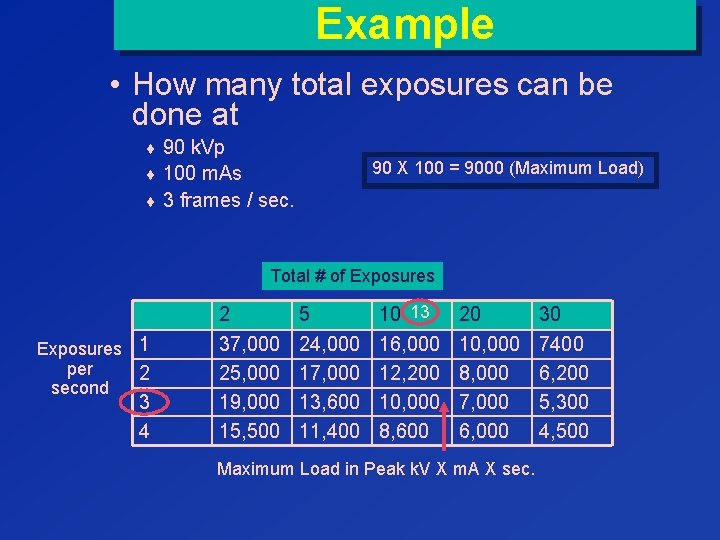
Example • How many total exposures can be done at ¨ 90 k. Vp 90 X 100 = 9000 (Maximum Load) ¨ 100 m. As ¨ 3 frames / sec. Total # of Exposures 1 per 2 second 3 4 2 37, 000 25, 000 19, 000 15, 500 5 24, 000 17, 000 13, 600 11, 400 10 13 16, 000 12, 200 10, 000 8, 600 20 10, 000 8, 000 7, 000 6, 000 Maximum Load in Peak k. V X m. A X sec. 30 7400 6, 200 5, 300 4, 500
Tube Rating Considerations • ability of tube to withstand multiple exposures during several hours of heavy use depends upon ¨ anode storage / cooling curves ¨ housing storage / cooling curves • housing cooling can be improved with ¨ fans ¨ oil / water circulators
Tube Damage Warning
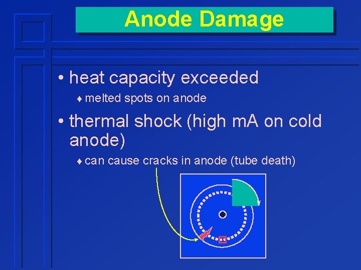
Anode Damage • heat capacity exceeded ¨ melted spots on anode • thermal shock (high m. A on cold anode) ¨ can cause cracks in anode (tube death)
Protecting the Anode • Tube warm-up • Eliminates thermal shock from high m. A exposures on cold anode • Warm-up needed whenever tube cold ¨ once in the morning not sufficient if tube not used for several hours
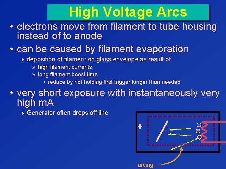
High Voltage Arcs • electrons move from filament to tube housing instead of to anode • can be caused by filament evaporation ¨ deposition of filament on glass envelope as result of » high filament currents » long filament boost time • reduce by not holding first trigger longer than needed • very short exposure with instantaneously very high m. A ¨ Generator often drops off line + arcing
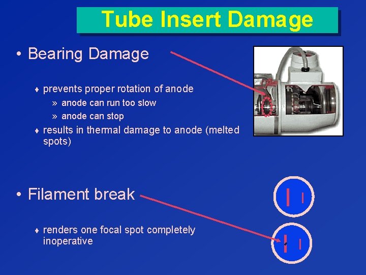
Tube Insert Damage • Bearing Damage ¨ prevents proper rotation of anode » anode can run too slow » anode can stop ¨ results in thermal damage to anode (melted spots) • Filament break ¨ renders one focal spot completely inoperative
Reducing Tube Wear: Lower m. A 80 k. Vp 500 m. A, 0. 1 sec 80 k. Vp or 100 m. A, 0. 5 sec • Both exposure are 50 m. As ¨ Same radiation to image receptor ¨ Same dose to patient Don’t smoke that tube
Reducing Tube Wear: Lower m. A 80 k. Vp 500 m. A, 0. 1 sec 80 k. Vp or 100 m. A, 0. 5 sec • Low m. A reduces tube wear ¨ filament temperatures lower ¨ reduces filament evaporation Don’t smoke that tube
Reducing Tube Wear: Lower m. A 80 k. Vp 500 m. A, 0. 1 sec 80 k. Vp or 100 m. A, 0. 5 sec • use lowest m. A (and largest focal spot) consistent with patient motion considerations • Large focal spot allows higher m. A to be used Don’t smoke that tube
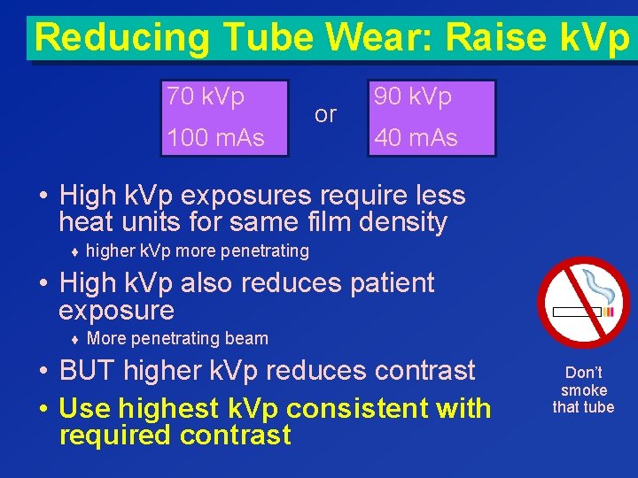
Reducing Tube Wear: Raise k. Vp 70 k. Vp 100 m. As or 90 k. Vp 40 m. As • High k. Vp exposures require less heat units for same film density ¨ higher k. Vp more penetrating • High k. Vp also reduces patient exposure ¨ More penetrating beam • BUT higher k. Vp reduces contrast • Use highest k. Vp consistent with required contrast Don’t smoke that tube
Reducing Tube Wear • Reduce use of high speed anode rotation ¨ use longer times instead of higher k. V and/or m. A • High speed rotation greatly increases bearing wear ¨ generators automatically select high speed for high combinations of k. V & m. A ¨ BUT longer exposure times » increase exposure time & patient motion ¨ use lowest m. A consistent with patient motion considerations Don’t smoke that tube
Reducing Tube Wear • Reduce first trigger holding time ¨ Reduces bearing wear » Reduces tube rotation time ¨ Reduces filament evaporation » filament evaporation can lead to tube arcing • Holding first trigger sometimes necessary ¨ synchronizing breathing for children Don’t smoke that tube
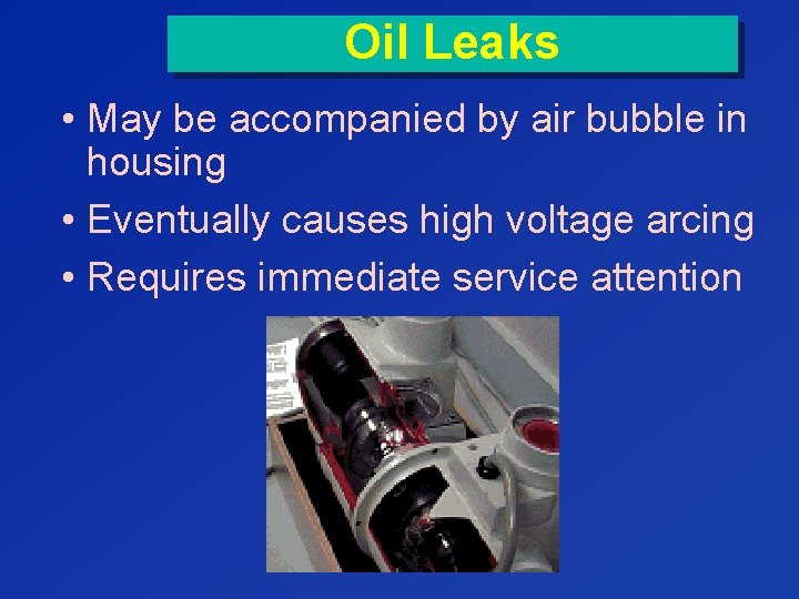
Oil Leaks • May be accompanied by air bubble in housing • Eventually causes high voltage arcing • Requires immediate service attention
- Slides: 36