
Requirements of technical systems V Parma TEMSC Outline


- Slides: 25
Requirements of technical systems V. Parma, TE-MSC Outline: Introduction Systems involved Cryogenic system Super-conducting bus bars Beam vacuum Other requirements Summary
Introduction Technical Working Group for the DS collimators in pt. 3 8 weekly meetings in last 2 months Chairs: A. Bertarelli+V. Parma Secretary: D. Ramos (minutes in https: //espace. cern. ch/dscollimator ) Participants: O. Aberle, R. Assmann, V. Baglin, A. Bertarelli, F. Cerutti, R. Principe, Th. Renaglia, D. Ramos, V. Parma, J. Ph. Tock, R. Van Weelderen • Goal: review specifications, feasibility of cold and warm options for installation in the 2012 shut-down, and review integration within LHC technical systems • Requirements in this presentation focused on the warm concept, “the 2012 option” • Most of this content is part of an Engineering Specification under preparation (editor: Delio Ramos) • • •
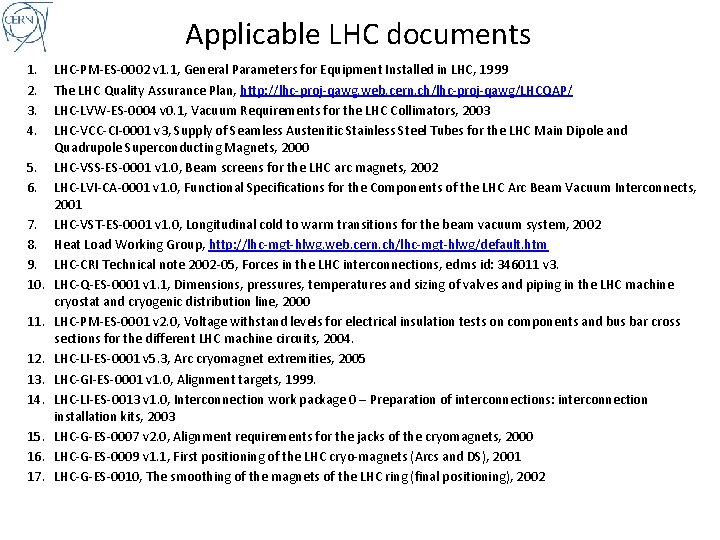
Applicable LHC documents 1. 2. 3. 4. 5. 6. 7. 8. 9. 10. 11. 12. 13. 14. 15. 16. 17. LHC-PM-ES-0002 v 1. 1, General Parameters for Equipment Installed in LHC, 1999 The LHC Quality Assurance Plan, http: //lhc-proj-qawg. web. cern. ch/lhc-proj-qawg/LHCQAP/ LHC-LVW-ES-0004 v 0. 1, Vacuum Requirements for the LHC Collimators, 2003 LHC-VCC-CI-0001 v 3, Supply of Seamless Austenitic Stainless Steel Tubes for the LHC Main Dipole and Quadrupole Superconducting Magnets, 2000 LHC-VSS-ES-0001 v 1. 0, Beam screens for the LHC arc magnets, 2002 LHC-LVI-CA-0001 v 1. 0, Functional Specifications for the Components of the LHC Arc Beam Vacuum Interconnects, 2001 LHC-VST-ES-0001 v 1. 0, Longitudinal cold to warm transitions for the beam vacuum system, 2002 Heat Load Working Group, http: //lhc-mgt-hlwg. web. cern. ch/lhc-mgt-hlwg/default. htm LHC-CRI Technical note 2002 -05, Forces in the LHC interconnections, edms id: 346011 v 3. LHC-Q-ES-0001 v 1. 1, Dimensions, pressures, temperatures and sizing of valves and piping in the LHC machine cryostat and cryogenic distribution line, 2000 LHC-PM-ES-0001 v 2. 0, Voltage withstand levels for electrical insulation tests on components and bus bar cross sections for the different LHC machine circuits, 2004. LHC-LI-ES-0001 v 5. 3, Arc cryomagnet extremities, 2005 LHC-GI-ES-0001 v 1. 0, Alignment targets, 1999. LHC-LI-ES-0013 v 1. 0, Interconnection work package 0 – Preparation of interconnections: interconnection installation kits, 2003 LHC-G-ES-0007 v 2. 0, Alignment requirements for the jacks of the cryomagnets, 2000 LHC-G-ES-0009 v 1. 1, First positioning of the LHC cryo-magnets (Arcs and DS), 2001 LHC-G-ES-0010, The smoothing of the magnets of the LHC ring (final positioning), 2002
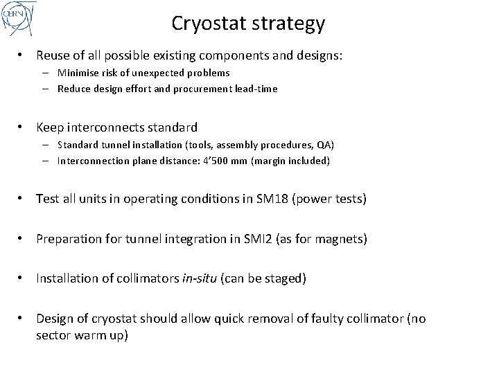
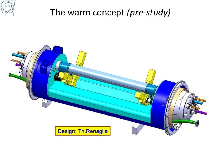
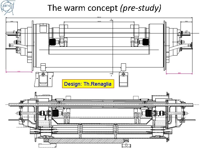
Cryostat strategy • Reuse of all possible existing components and designs: – Minimise risk of unexpected problems – Reduce design effort and procurement lead-time • Keep interconnects standard – Standard tunnel installation (tools, assembly procedures, QA) – Interconnection plane distance: 4’ 500 mm (margin included) • Test all units in operating conditions in SM 18 (power tests) • Preparation for tunnel integration in SMI 2 (as for magnets) • Installation of collimators in-situ (can be staged) • Design of cryostat should allow quick removal of faulty collimator (no sector warm up)
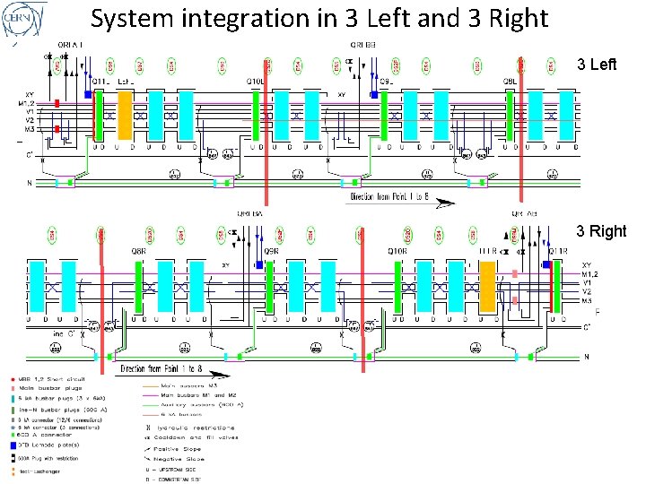
System integration in 3 Left and 3 Right 3 Left 3 Right
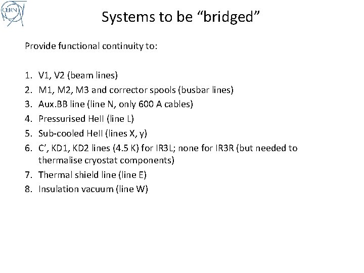
Systems to be “bridged” Provide functional continuity to: 1. 2. 3. 4. 5. 6. V 1, V 2 (beam lines) M 1, M 2, M 3 and corrector spools (busbar lines) Aux. BB line (line N, only 600 A cables) Pressurised He. II (line L) Sub-cooled He. II (lines X, y) C’, KD 1, KD 2 lines (4. 5 K) for IR 3 L; none for IR 3 R (but needed to thermalise cryostat components) 7. Thermal shield line (line E) 8. Insulation vacuum (line W)
The warm concept (pre-study) Design: Th. Renaglia
The warm concept (pre-study) Design: Th. Renaglia
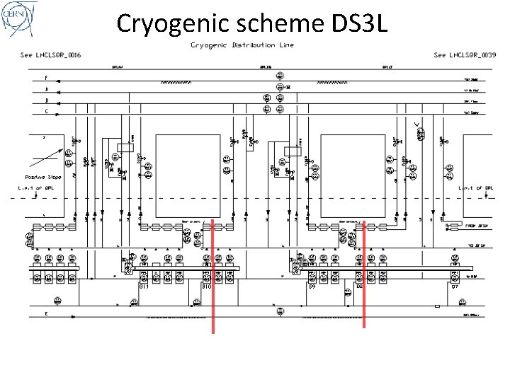
Cryogenic scheme DS 3 L
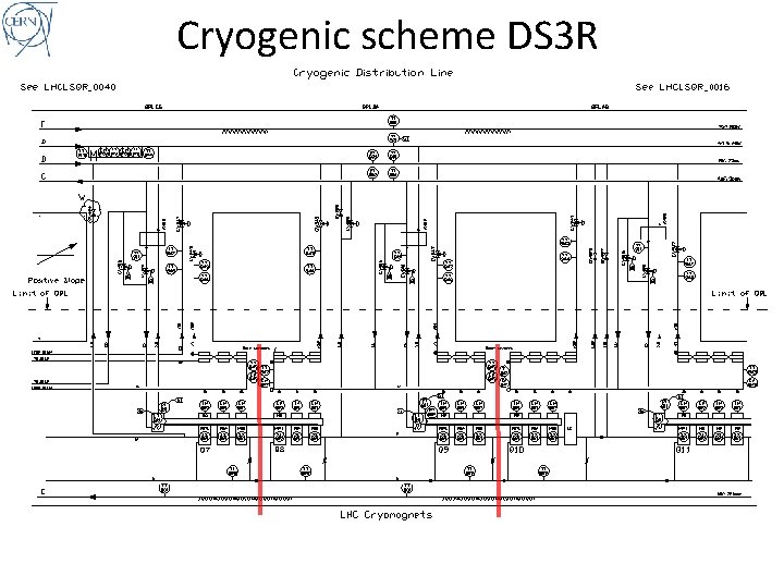
Cryogenic scheme DS 3 R
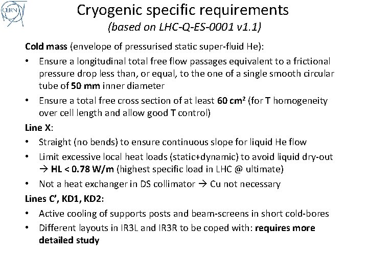
Cryogenic specific requirements (based on LHC-Q-ES-0001 v 1. 1) Cold mass (envelope of pressurised static super-fluid He): • Ensure a longitudinal total free flow passages equivalent to a frictional pressure drop less than, or equal, to the one of a single smooth circular tube of 50 mm inner diameter • Ensure a total free cross section of at least 60 cm 2 (for T homogeneity over cell length and allow good T control) Line X: • Straight (no bends) to ensure continuous slope for liquid He flow • Limit excessive local heat loads (static+dynamic) to avoid liquid dry-out HL < 0. 78 W/m (highest specific load in LHC @ ultimate) • Not a heat exchanger in DS collimator Cu not necessary Lines C’, KD 1, KD 2: • Active cooling of supports posts and beam-screens in short cold-bores • Different layouts in IR 3 L and IR 3 R to be coped with: requires more detailed study
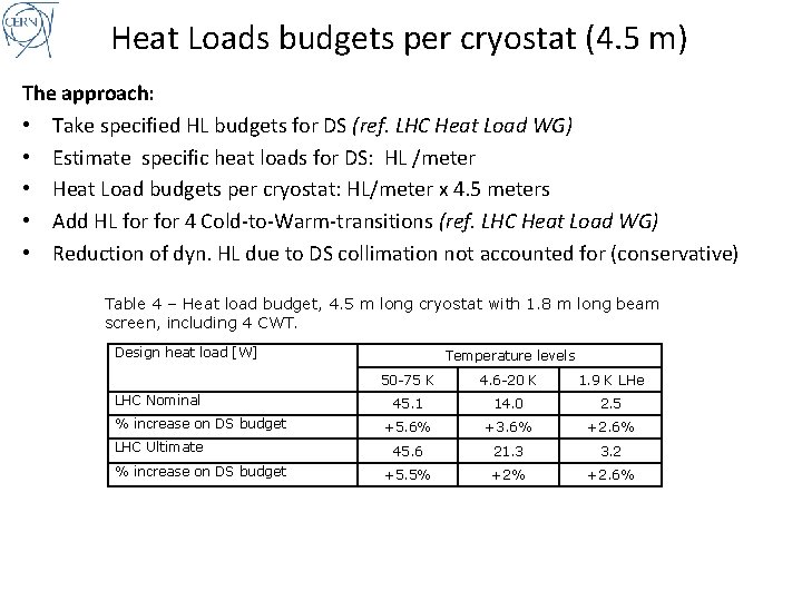
Heat Loads budgets per cryostat (4. 5 m) The approach: • Take specified HL budgets for DS (ref. LHC Heat Load WG) • Estimate specific heat loads for DS: HL /meter • Heat Load budgets per cryostat: HL/meter x 4. 5 meters • Add HL for 4 Cold-to-Warm-transitions (ref. LHC Heat Load WG) • Reduction of dyn. HL due to DS collimation not accounted for (conservative) Table 4 – Heat load budget, 4. 5 m long cryostat with 1. 8 m long beam screen, including 4 CWT. Design heat load [W] LHC Nominal % increase on DS budget LHC Ultimate % increase on DS budget Temperature levels 50 -75 K 4. 6 -20 K 1. 9 K LHe 45. 1 14. 0 2. 5 +5. 6% +3. 6% +2. 6% 45. 6 21. 3 3. 2 +5. 5% +2. 6%
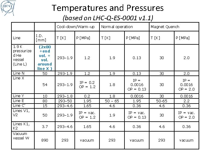
Temperatures and Pressures (based on LHC-Q-ES-0001 v 1. 1) Line 1. 9 K pressurize d He vessel (Line L) Line N Line X Line Y Line E Line C’ Lines V 1, V 2 Lines K 1, K 2 Vacuum vessel W I. D. [mm] (2 x 80 +end vol. + vol. around line X ) 50 Cool-down/Warm-up Normal operation Magnet Quench T [K] P [MPa] 293– 1. 9 1. 2 1. 9 0. 13 30 2. 0 293 -1. 9 1. 2 1. 9 0. 13 30 2. 0 54 293– 1. 9 IP = 0. 2 OP = 1. 2 1. 8 IP = 0. 0016 OP = 0. 13 30 IP = 0. 0016 OP = 2. 0 10 80 15 293– 1. 8 293– 50 293– 4. 6 0. 2 1. 95 1. 65 1. 8 50 – 65 4. 6 0. 0016 1. 95 0. 36 30 50 -65 4. 6 0. 0016 2. 2 0. 36 50 293– 1. 9 IP = vac. OP = 1. 2 1. 9 IP = vac. OP = 0. 13 30 IP = vac. OP = 2. 0 3. 7 293– 4. 6 1. 65 4. 6 0. 36 890 293 vacuum
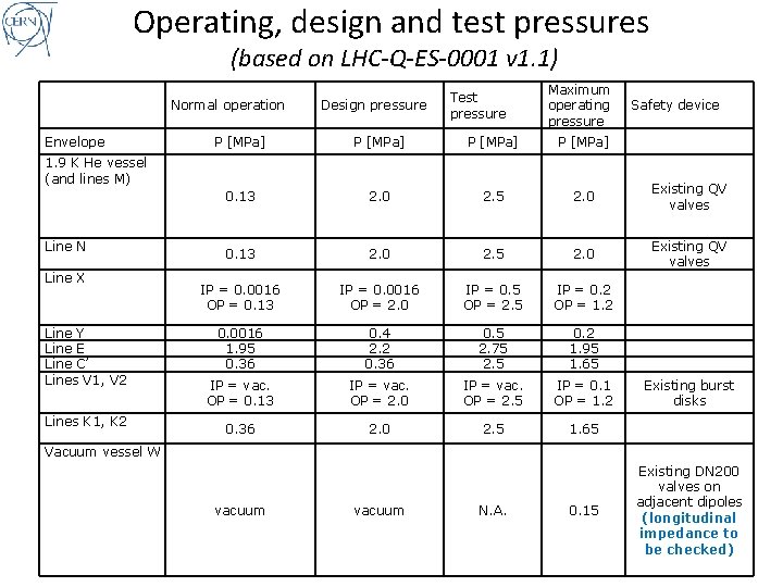
Operating, design and test pressures (based on LHC-Q-ES-0001 v 1. 1) Normal operation Envelope Design pressure Test pressure Maximum operating pressure P [MPa] 0. 13 2. 0 2. 5 2. 0 Existing QV valves IP = 0. 0016 OP = 0. 13 IP = 0. 0016 OP = 2. 0 IP = 0. 5 OP = 2. 5 IP = 0. 2 OP = 1. 2 0. 0016 1. 95 0. 36 0. 4 2. 2 0. 36 0. 5 2. 75 2. 5 0. 2 1. 95 1. 65 IP = vac. OP = 0. 13 IP = vac. OP = 2. 0 IP = vac. OP = 2. 5 IP = 0. 1 OP = 1. 2 0. 36 2. 0 2. 5 1. 65 1. 9 K He vessel (and lines M) Line N Line X Line Y Line E Line C’ Lines V 1, V 2 Lines K 1, K 2 Safety device Existing burst disks Vacuum vessel W vacuum N. A. 0. 15 Existing DN 200 valves on adjacent dipoles (longitudinal impedance to be checked)
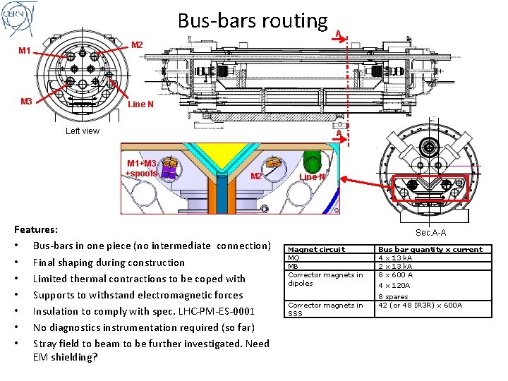
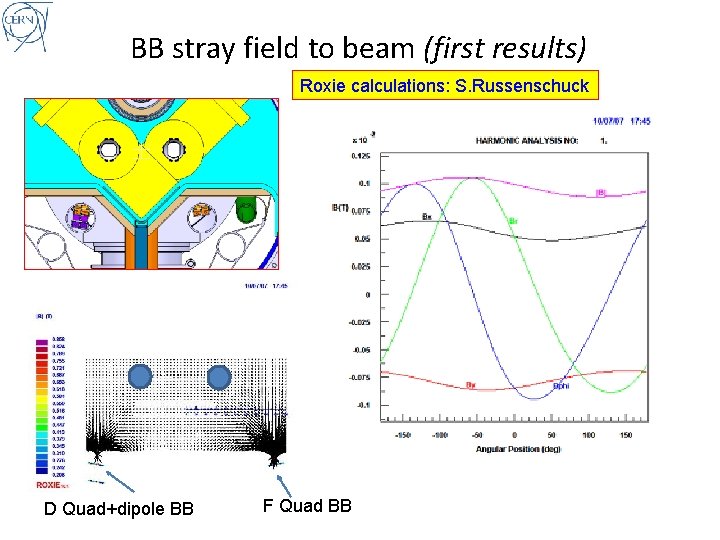
Bus-bars routing A M 2 M 1 M 3 Line N Left view A M 1+M 3 +spools M 2 Features: • Bus-bars in one piece (no intermediate connection) • Final shaping during construction • Limited thermal contractions to be coped with • Supports to withstand electromagnetic forces • Insulation to comply with spec. LHC-PM-ES-0001 • No diagnostics instrumentation required (so far) • Stray field to beam to be further investigated. Need EM shielding? Line N Sec. A-A Magnet circuit MQ MB Corrector magnets in dipoles Corrector magnets in SSS Bus bar quantity x current 4 x 13 k. A 2 x 13 k. A 8 x 600 A 4 x 120 A 8 spares 42 (or 48 IR 3 R) x 600 A
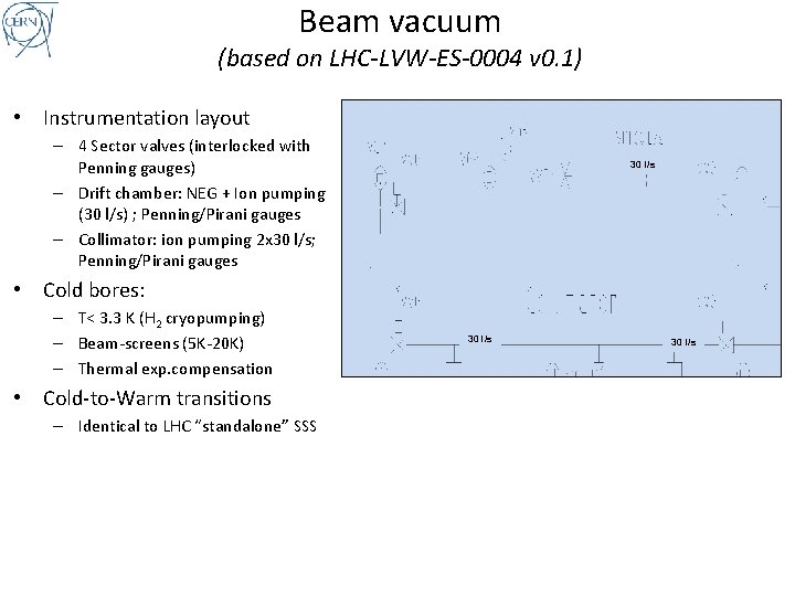
Beam vacuum (based on LHC-LVW-ES-0004 v 0. 1) • Instrumentation layout – 4 Sector valves (interlocked with Penning gauges) – Drift chamber: NEG + Ion pumping (30 l/s) ; Penning/Pirani gauges – Collimator: ion pumping 2 x 30 l/s; Penning/Pirani gauges 30 l/s • Cold bores: – T< 3. 3 K (H 2 cryopumping) – Beam-screens (5 K-20 K) – Thermal exp. compensation • Cold-to-Warm transitions – Identical to LHC “standalone” SSS 30 l/s
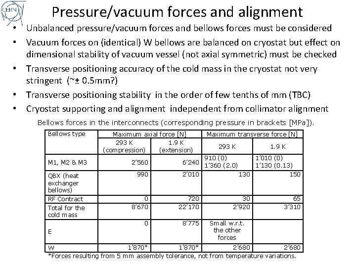
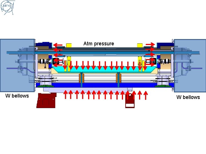
Pressure/vacuum forces and alignment • Unbalanced pressure/vacuum forces and bellows forces must be considered • Vacuum forces on (identical) W bellows are balanced on cryostat but effect on dimensional stability of vacuum vessel (not axial symmetric) must be checked • Transverse positioning accuracy of the cold mass in the cryostat not very stringent (~± 0. 5 mm? ) • Transverse positioning stability in the order of few tenths of mm (TBC) • Cryostat supporting and alignment independent from collimator alignment Bellows forces in the interconnects (corresponding pressure in brackets [MPa]). Bellows type M 1, M 2 & M 3 QBX (heat exchanger bellows) RF Contract Total for the cold mass E Maximum axial force [N] 293 K 1. 9 K (compression) (extension) 2’ 560 Maximum transverse force [N] 293 K 1. 9 K 910 (0) 6’ 240 1’ 360 (2. 0) 1’ 010 (0) 1’ 130 (0. 13) 990 2’ 010 130 150 0 8’ 670 720 22’ 170 30 2’ 920 65 3’ 310 0 8’ 775 Small w. r. t. the other forces 1’ 870* 2’ 680 W *Forces resulting from 5 mm assembly tolerance, not from temperature variations.
Atm pressure W bellows
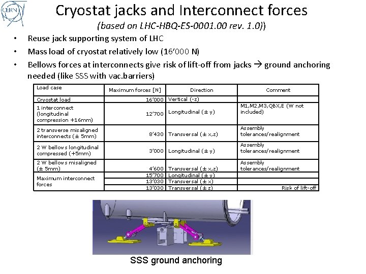
Cryostat jacks and Interconnect forces (based on LHC-HBQ-ES-0001. 00 rev. 1. 0)) • • • Reuse jack supporting system of LHC Mass load of cryostat relatively low (16’ 000 N) Bellows forces at interconnects give risk of lift-off from jacks ground anchoring needed (like SSS with vac. barriers) Load case Cryostat load 1 interconnect (longitudinal compression +16 mm) Maximum forces [N] Direction Comment 16’ 000 Vertical (-z) 12’ 700 Longitudinal (± y) M 1, M 2, M 3, QBX, E (W not included) 2 transverse misaligned interconnects (± 5 mm) 8’ 430 Transversal (± x, z) Assembly tolerances/realignment 2 W bellows longitudinal compressed (+5 mm) 3’ 000 Longitudinal (± y) Assembly tolerances/realignment 2 W bellows misaligned (± 5 mm) Maximum interconnect forces 4’ 600 15’ 700 13’ 030 Transversal (± x, z) Longitudinal (± y) Transversal (± x) Transversal (± z) SSS ground anchoring Assembly tolerances/realignment Risk of lift-off
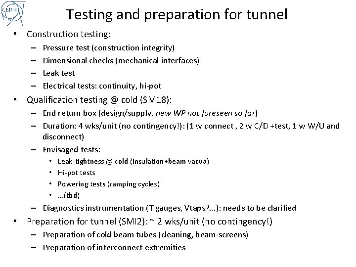
Testing and preparation for tunnel • Construction testing: – – Pressure test (construction integrity) Dimensional checks (mechanical interfaces) Leak test Electrical tests: continuity, hi-pot • Qualification testing @ cold (SM 18): – End return box (design/supply, new WP not foreseen so far) – Duration: 4 wks/unit (no contingency!): (1 w connect , 2 w C/D +test, 1 w W/U and disconnect) – Envisaged tests: • • Leak-tightness @ cold (insulation+beam vacua) Hi-pot tests Powering tests (ramping cycles). . . (tbd) – Diagnostics instrumentation (T gauges, Vtaps? . . . ): needs to be clarified • Preparation for tunnel (SMI 2): ~ 2 wks/unit (no contingency!) – Preparation of cold beam tubes (cleaning, beam-screens) – Preparation of interconnect extremities
Other requirements • Radiation shielding needed? – Lead shielding was a (tough!) requirement in the LHC CC – Needed in the DS cryostats? To be decided by experts • Reliability: – Cryostat shall be maintenance-free – Collimator shall be removable in-situ and replaced by drift tubes • . . .
Summary • The study carried out in the last two months allowed reviewing specifications and feasibility of the cold and warm options for DS collimators to be installed in the 2012 shut-down • Warm option is the “ 2012 solution” • Integration needs for the cryostats within LHC technical systems could be reviewed and have led to additional requirements • No technical show-stoppers have been identified so far • . . . but this was only a pre-study, more work is still needed (e. g. magnetic and radiation shielding) • An Engineering Specification for the DS collimators is in progress and will be the basis for the design of the DS collimators • The technical challenge is certainly at reach but the engineering and construction effort is not to be underestimated • The cryostat should NOT be underestimated, it is far from being an “empty cryostat”. . . Let’s not repeat the same mistakes made on the LHC Connection Cryostats !
Thank you for your attention!
Spare slides
BB stray field to beam (first results) Roxie calculations: S. Russenschuck D Quad+dipole BB F Quad BB