Requirements Engineering Requirements Analysis Software Modeling Data Model


")
 �Fact finding �Investigate")
 �DFDs describe the flow of data or information into and")
 - people or organisations that send data into")


- Slides: 37
Requirements Engineering
Requirements Analysis
Software Modeling Data Model �structure of the information, e. g. , ER diagram Function and Information Flow Model �what we will do with the data, e. g. , DFD, Use-Case Behavior Model �how we interact with the system, e. g. , State Transition Diagram
Data Flow Diagram (DFD)
Where do they fit in? �Analysis (What do we do? ) �Fact finding �Investigate business process and the current system �Modelling the current and required systems �Deliverables �Requirements specification �Logical models of the required system
Data Flow Diagrams (DFD) �DFDs describe the flow of data or information into and out of a system �what does the system do to the data? �A DFD is a graphic representation of the flow of data or information through a system 3
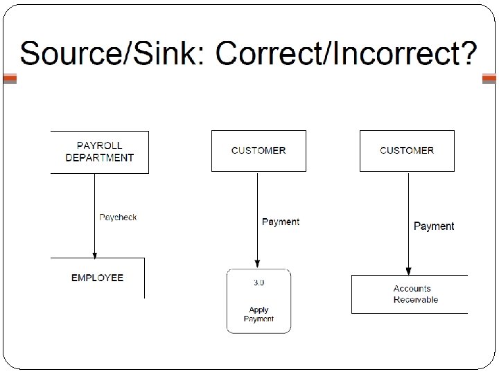
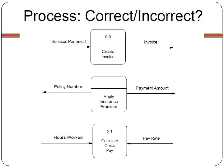
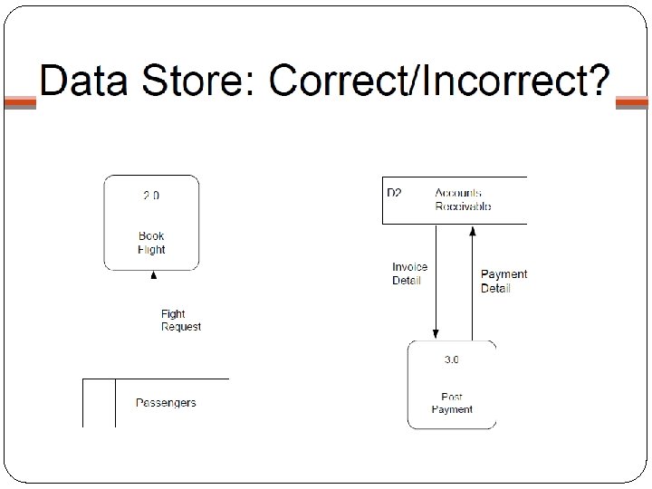
4 Main Elements �External Entity (Source/Sink) - people or organisations that send data into the system or receive data from the system �Process - models what happens to the data i. e. transforms incoming data into outgoing data �Data Store - represents permanent data that is used by the system �Data Flow - models the actual flow of the data between the other elements
Notation
Levelled DFDs �Even a small system could have many processes and data flows and DFD could be large and messy �use levelled DFDs - view system at different levels of detail �one overview and many progressively greater detailed views 4
Level 0 - Context Diagram �Models system as one process box which represents scope of the system �Identifies external entities and related inputs and outputs �Additional notation - system box Data Flow Out System Data Flow In External Entity
Level 1 – Overview Diagram �Gives overview of full system �Identifies major processes and data flows between them �Identifies data stores that are used by the major processes �Boundary of level 1 is the context diagram
Level 2 – Detailed Diagram �Level 1 process is expanded into more detail �Each process in level 1 is decomposed to show its constituent processes �Boundary of level 2 is the level 1 process
Rules for DFDs �Numbering �Labelling �Balancing
Numbering �On level 1 processes are numbered 1, 2, 3… �On level 2 processes are numbered x. 1, x. 2, x. 3… where x is the number of the parent level 1 process �Number is used to uniquely identify process not to represent any order of processing �Data store numbers usually D 1, D 2, D 3. . .
Labelling �Process label - short description of what the process does, e. g. , price order �Data flow label - noun representing the data flowing through it, e. g. , customer payment �Data store label - describes the type of data stored �Make labels as meaningful as possible
Balancing �any data flows entering or leaving a parent level must by equivalent to those on the child level �Data stores �data stores that are local to a process need not be included until the process is expanded �Data Flows �Allowed to combine several data flows from lower level diagrams at a higher level under one data flow to reduce clutter �Flows should be labelled except when data to or from a data store consists of all items in the data store
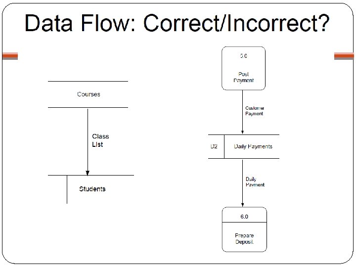
Rules for Using DFD Symbols YES A process to another process A process to an external entity A process to a data store An external entity to another external entity An external entity to a data store A data store to another data store NO
List the Errors of this DFD
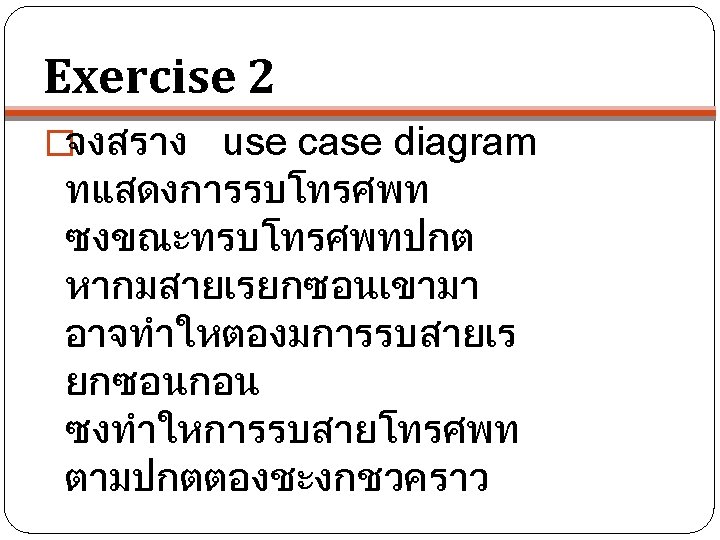
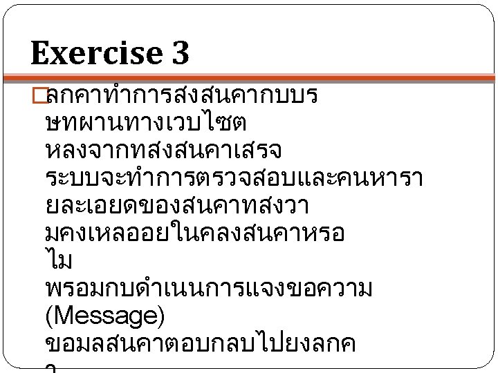
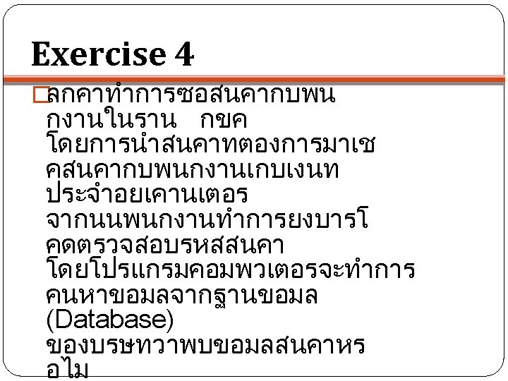
Use Case Diagram
Use Case Diagram �Use Case diagram is used to identify system requirements �Identify actors (users) of the system �Comparable to Context Diagram of DFD
Use Case Diagram: Notation Actor represents stakeholder or user of the system Use Case is a function of the system “association” is the relation between actor and use case “extend” and “include” are relations between use cases
Extend & Include �Stereotype <<extend>> is used to specify that a use case is extending another use case �Usually, an extending use case is adding extra function to the extended use case �Stereotype <<include>> OR <<use>> is used to specify that a use case is including other use cases �Usually, an included use case is a common function which is shared by many other use cases
Use Case Description �Text describing the use case �Example �Use Case Name: �Actors: �Precondition: �Postcondition: �Stakeholder: �Description: �Scenario:
Use Case Diagram Example
Use Case Description Example Use Case Name: Withdraw Actors: Customer Precondition: Customer enters correct pin number Postcondition: Customer receives correct amount of cash Stakeholder: Customer, ATM, Bank Description: The withdrawal from customer’s account via ATM Scenario: Next Slide
Example Scenario 1. Customer enters the amount to withdraw 2. System checks if the amount is valid 2. 1 The amount is valid, go to 3 2. 2 The amount is invalid, go to 4 3. ATM displays transaction and give out cash, go to 5 4. ATM displays an error message, go to 5 5. End