requirements Adv LIGO optical layout Adv LIGO PSL


 by Innolight* • output power: 800 m.")


 master laser, output power: 800")


 • each 10 X")


")

 500 m")

 500 m")
")


- Slides: 70
requirements
Adv. LIGO – optical layout
Adv. LIGO PSL – subsystem layout power stabilizaiton front end 20 W power stages 200 W premode cleaner 170 W reference cavity frequency stabilization mode cleaner long baseline cavities
Advanced LIGO PSL – requirements Power / Beamprofile: – 165 W in gausian TEM 00 mode – less than 5 W in non- TEM 00 modes Drift: – 1% power drift over 24 hr. – 2% pointing drift Control: – tidal frequency acuator +/- 50 MHz, time constant < 30 min – power actuator 10 k. Hz BW, +/-1% range – frequency actuatot BW: <20 o lag at 100 k. Hz, range: DC-1 Hz: 1 MHz, 1 Hz-100 k. Hz: 10 k. Hz
frequency noise requirement
intensity noise requirement
further PSL requirements • interfaces to detector control software • interfaces to DAQ system • environmental requirements: size, power, cooling • reliability to meet detector duty cycle goal • easy to maintain (change of items with lifetimes < 2 years)
concept
PSL optical layout high power ring laser 200 W GEO typ ring laser 15 W spatial filter resonator (PMC) NPRO 1 W frequency reference resonator AOM
Advanced LIGO Laser Design output f QR NPRO f FI BP FI f QR HR@1064 HT@808 EOM f modemaching optics f 2 f f YAG / Nd: YAG / YAG 3 x 7 x 40 x 7 High Power Slave YAG / Nd: YAG 3 x 2 x 6 BP 20 W Master
PSL – stabilization scheme intensity stabilization outer loop injection locking intensity stabilization inner loop PMC loop frequency stabilization inner loop frequency stabilization outer loop
pre-stabilized -LIGO 10 W laser length controll intensity controller NPRO EO pre-mode cleaner power amplifier to suspended mode cleaner temp PZT EO phase shifter frequency contoller AO mixer reference cavity
LIGOI reference cavity, AOM, tidal correction
pre-modecleaner • 713 MHz free spectral range • linewidth: 162 k. Hz in s-pol. , 3. 2 MHz in p-pol. • circulating power 0. 135 MW/cm 2 (for p-pol. ), 2. 64 MW/cm 2 (for s-pol. ) • linewidth required to filter RIN(@25 MHz) of 180 W laser: 3. 7 MHz
status
PSL set-up high power ring laser 200 W GEO typ ring laser 15 W spatial filter resonator (PMC) NPRO 1 W frequency reference resonator AOM
Nd: YAG Master-Laser NPRO (non-planar ring oscillator) by Innolight* • output power: 800 m. W • frequency noise: [ 10 k. Hz/f ] Hz/sqrt(Hz) • power noise: 10 -6 /sqrt(Hz) * US dristibution: Resonant optics Corp. , San Martin CA
High Power Locking Scheme Master • 2 W Miser Mephisto 2000 Innolight • EOM: New Focus @ 29, 02 MHz • Isolator: Gsänger
GEO 600 Slave Laser
performance of the LIGOI frequency stab
High Power Locking Scheme Medium Stage • 12 W med. power stage based on GEO 600 laser design opt ~ 30 % • Isolator: Gsänger high power design
GEO 600 Slave Laser Prototype II Frequency Stability
12 W injection-locked laser-system • NPRO (non-planar ring oscillator) master laser, output power: 800 m. W • slave laser optical components mounted on rigid resonator-spacer (Invar) • 12 W output power (< 5% in higher TEM modes) • injection-locking stable over days
High Power Slave • 87 W output power • linear polarized • single transverse mode • M 2 x, y ~ 1, 2
Experimental/Diode Temperature Control laser diode JENOPTIK 30 W, fiber coupled, NA 0. 22; 800 m temperature resolution: 0. 01 K temperature fluctuations: 2 -3 digits temperature stability better than 0. 05 K
Experimental/Diode Box • 4 boxes user interface 4 systems (boxes) • each 10 X 30 W fiber-coupled diodes 1200 W pump Power 40 temperatures 4 current controls (1 per box) laser diode (10) heat sink (2) ADC/DAC upcoming: • 40 diode power measurements laser power control for each diode overtemp interlocks peltier drivers
High Power Locking Scheme • 87 W high power slave single transverse mode M 2 ~ 1, 2 opt ~ 23 %
High Power Locking Scheme
Results First high power injection locked laser system 87 W linear polarized, single frequency, single transverse mode ( total power of all systems ~ 101 W ) total optical efficiency 22% locking direct to 2 W master possible single frequency output power ~ 70 W
Beam Characterization Beat signals of free running slave no higher order modes detect Beam profile of locked system M 2~1. 1 , less elliptical beam
Relock Time relock time < 500 ms faster relock possible depending on piezo ramp
System Optimization To get full injection locked power following things has to be optimized: • Modemaching in the high power slave ( FI with compensated thermal lens ) • Outputcoupler of high power slave • optimize gain overlap of different Lasers • implement pumplight optimization
next steps
Pump Concepts mode selective pumping w = 1 mm
Pump Light Homogenization 30 % more output power with homogenization better gain overlap and less distortion for low order modes
New Head Design
Pump Chamber water flow 2. 5 cm
Birefringence compensation Find working point with less birefringence
Pump Light Homogenization fluorescence w/o homogenization
Homogenization of Pump Light simulation 10 x 800 µm measured 30 x 800 µm
Pump Concepts mode selective pumping w = 2 mm
Optimization of Pump Light Distribution • alignment of homogenous and centered pump light profile • pump power calibration for PD-readout
Optimize Resonator • Test different laser rods 4, 5 mm • Test different pump spot sizes find best laser design before doubling the system
Advanced Ligo Laser 1 st. Step • Optimized laser head with respect to beam quality and output power • up to now 100 W of output power in single transverse mode are demonstrated
Advanced Ligo Laser 2 st. Step output f QR f BP from Master f QR HR@1064 HT@808 f f 2 f f
Modeling/Overview pump light distribution • ray tracing • analytical approximation • experimental data heat generation gain wave propagation through inhomogenous medium • finite differencing • split step fourier approach Finite Element Method for calculating • temperature distribution • mechanical stress • deformation cooling calculation of optical properties k-vector • thermal lens • stress-induced birefringence
Model assumption: cylinder symmetrical pump light distribution • model takes into account temperature dependent properties wavelength dependent absorption coefficient temperature dependent heat conducitvity temperature dependent expansion coefficient temperature dependent dn/d. T
Fox/Li Approach Iterative Solution of Kirchhoff integral equations initial distributed E(x, y, z 0) (e. g. noise) medium free propagation mirror/aperture free propagation • inhomogenous distributed gain, refractive index, birefringence concentrated in gain/phase sheets • propagation between gain/phase sheets and in free space described by FFT propagator medium free Propagation mirror/aperture output power beam quality free Propagation no convergence ? yes
Abberations/End Pumped vs. Transversally Pumped <10 nm
Thermal Modeling/Temperature Distribution varying with pump spot diameter (pump power kept constant) 500 m
Thermal Modeling/Maximum Temperature
Von Mises Stress varying with pump spot diameter (pump power kept constant) 500 m
Mechanical Stress/Von Mises Equivalent Stress varying with pump spot diameter (pump power kept constant)
Resumé • Modeling • 100 W of output power will be achieveable • abberations will have to be compensated for • abberations are comparable in end pumped and transversally pumped rod • Experimental • 4 diode boxes have been set up (1200 W of pump power) • temperature stabilization works • pump light homogenization has been demonstrated • 45 W single mode and 75 W multi mode laser has been demonstrated (single rod, no compensation)
alt. concept
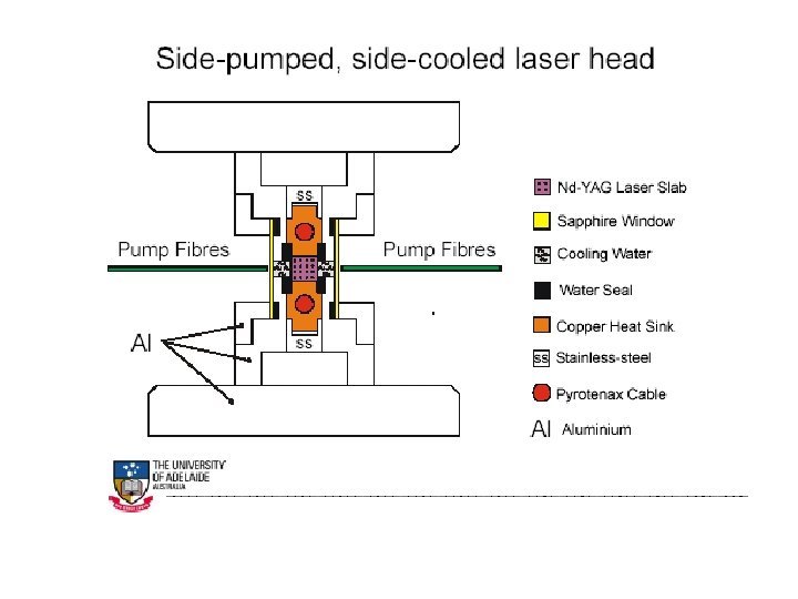
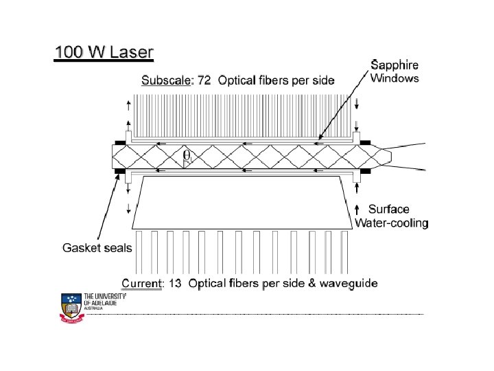
Face-pumping vs Edge-pumping Pumping zig-zag slab Facepumping zig-zag plane Cooling Edgepumping zig-zag plane Pumping Cooling
Experimental Setup for 100 W demonstration 10 W LIGO MOPA System Mode-matching optics ISOL ATOR Mode-matching Output Power = 32 W optics 20 W Amplifier Lightwave Electronics Edge Pumped Slab #1 Mode-matching optics Mode-matching End Pumped Slab optics Output Power = 110 W Edge Pumped Slab #2 Pump Power = 300 W Pump Power = 420 W Output Power = 65 W
10 W LIGO Laser Characteristics: • Single frequency. • TEM 00 • Narrow linewidth. • Low frequency & amplitude noise. 10 W Amplifier 400 m. W NPRO
Nd: YAG Laser Head 3. 8 cm
End pumped slab geometry Motivation -> Higher efficiency • Near total absorption of pump light. 808 nm Pump undoped end signal OUT • Confinement of pump radiation leads to better mode overlap 3. 33 cm 1. 51 cm 0. 6% Nd: YAG signal IN 808 nm Pump undoped end 1. 1 mm X 0. 9 mm
What next for the 100 W experiment? 10 W LIGO MOPA System Mode-matching optics ISOL ATOR Mode-matching Output Power = 35 W optics 20 W Amplifier Lightwave Electronics Key: Improve absorption of pump light and achieve the expected small signal gain. 2 -pass End Pumped Slab Pump Power = 230 W Expected Output Power = 100 W Edge Pumped Slab #1 Mode-matching optics
Scaling to 200 W : Experimental Plan 10 W LIGO MOPA System Mode-matching optics 20 W Amplifier ISOL ATOR Pump Power = 130 Output TEM 00 Power = 50 W Lightwave Electronics 2 -pass End Pumped Slab #1 Mode-matching optics 2 -pass End Pumped Slab #2 TO PRE MODE CLEANER Pump Power = 430 W Expected TEM 00 Output Power = 160 W
WBS plan
manpower costing
the LIGOII laser-team Laser Zentrum Hannover High-power solidstate-lasers design Stanford Adelaide Max-Planck Institut University of Glasgow University of Hannover power and frequency stabilization GEO 600 pre-stabilized laser LIGOII pre-stabilized laser LIGO Lab
German proposal