Requirement Engineering Lecture 7 Review Analysis Modeling Structured


 2) 3) 4) 5) 6) 7) Perform a grammatical parse")


 • General classifications for a potential class – – –")


 2) Identify events found within the use cases and")


 for the Safe. Home security function")


 template TABLE OF CONTENTS 1. 0 Introduction 1. 1 Purpose")


: – STS shall allow the")

 – 3. 2 Design Constraints • • • SRS-031 (3.")
: STS")


 • Do any requirements conflict with other")


- Slides: 59
Requirement Engineering Lecture 7
Review • Analysis Modeling – Structured analysis – Object oriented analysis • Object Oriented Analysis – Scenario Based Modeling (Use Cases, Swim lane Diagrams, Activity Diagrams)
Contents • Flow Oriented Modeling • Class Based Modeling
Flow-Oriented Modeling
Guidelines • Depict the system as single bubble in level 0. • Carefully note primary input and output. • Refine by isolating candidate processes and their associated data objects and data stores. • Label all elements with meaningful names. • Maintain information conformity between levels. • Refine one bubble at a time.
Data Flow Diagram Context-level DFD for Safe. Home security function
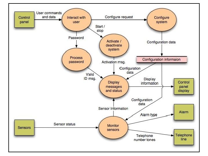
Level 2 DFD that refines the monitor sensors process
Control Flow Diagram State diagram for Safe. Home security function
Processing narrative • The Safe. Home security function enables the homeowner to configure the security system when it is installed, monitors all sensors connected to the security system, and interacts with the homeowner through the Internet, a PC, or a control panel. • During installation, the Safe. Home PC is used to program and configure the system. Each sensor is assigned a number and type, a master password is programmed for arming and disarming the system, and telephone number(s) are input for dialing when a sensor event occurs. • When a sensor event is recognized, the software invokes an audible alarm attached to the system. After a delay time that is specified by the homeowner during system configuration activities, the software dials a telephone number of a monitoring service, provides information about the location, reporting the nature of the event that has been detected. The telephone number will be redialed every 20 seconds until a telephone connection is obtained. • The homeowner receives security information via a control panel, the PC, or a browser, collectively called an interface. The interface displays prompting messages and system status information on the control panel, the PC, or the browser window. Homeowner interaction takes the following form…
Class-based Modeling
Identifying Analysis Classes 1) 2) 3) 4) 5) 6) 7) Perform a grammatical parse of the problem statement or use cases Classes are determined by underlining each noun or noun clause A class required to implement a solution is part of the solution space A class necessary only to describe a solution is part of the problem space A class should NOT have an imperative procedural name (i. e. , a verb) List the potential class names in a table and "classify" each class according to some taxonomy and class selection characteristics A potential class should satisfy nearly all (or all) of the selection characteristics to be considered a legitimate problem domain class Potential classes General classification (More on next slide) Selection Characteristic s
Grammatical Parse • The Safe. Home security function enables the homeowner to configure the security system when it is installed, monitors all sensors connected to the security system, and interacts with the homeowner through the Internet, a PC, or a control panel. • During installation, the Safe. Home PC is used to program and configure the system. Each sensor is assigned a number and type, a master password is programmed for arming and disarming the system, and telephone number(s) are input for dialing when a sensor event occurs. • When a sensor event is recognized, the software invokes an audible alarm attached to the system. After a delay time that is specified by the homeowner during system configuration activities, the software dials a telephone number of a monitoring service, provides information about the location, reporting the nature of the event that has been detected. The telephone number will be redialed every 20 seconds until a telephone connection is obtained. • The homeowner receives security information via a control panel, the PC, or a browser, collectively called an interface. The interface displays prompting messages and system status information on the control panel, the PC, or the browser window. Homeowner interaction takes the following form…
Grammatical Parse • The Safe. Home security function enables the homeowner to configure the security system when it is installed, monitors all sensors connected to the security system, and interacts with the homeowner through the Internet, a PC, or a control panel. • During installation, the Safe. Home PC is used to program and configure the system. Each sensor is assigned a number and type, a master password is programmed for arming and disarming the system, and telephone number(s) are input for dialing when a sensor event occurs. • When a sensor event is recognized, the software invokes an audible alarm attached to the system. After a delay time that is specified by the homeowner during system configuration activities, the software dials a telephone number of a monitoring service, provides information about the location, reporting the nature of the event that has been detected. The telephone number will be redialed every 20 seconds until a telephone connection is obtained. • The homeowner receives security information via a control panel, the PC, or a browser, collectively called an interface. The interface displays prompting messages and system status information on the control panel, the PC, or the browser window. Homeowner interaction takes the following form…
Identifying Analysis Classes (continued) • General classifications for a potential class – – – – External entity (e. g. , another system, a device, a person) Thing (e. g. , report, screen display) Occurrence or event (e. g. , movement, completion) Role (e. g. , manager, engineer, salesperson) Organizational unit (e. g. , division, group, team) Place (e. g. , manufacturing floor, loading dock) Structure (e. g. , sensor, vehicle, computer) (More on next slide)
Class Selection Criteria 1. 2. 3. 4. 5. 6. Retained information Needed services Multiple attributes Common operations Essential requirements
Identifying Classes Potential class Classification Accept / Reject homeowner role; external entity reject: 1, 2 fail sensor external entity accept control panel external entity accept installation occurrence reject (security) system thing accept number, type not objects, attributes reject: 3 fails master password thing reject: 3 fails telephone number thing reject: 3 fails sensor event occurrence accept audible alarm external entity accept: 1 fails monitoring service organizational unit; ee reject: 1, 2 fail
Defining Attributes of a Class • Attributes of a class are those nouns from the grammatical parse that reasonably belong to a class • Attributes hold the values that describe the current properties or state of a class • An attribute may also appear initially as a potential class that is later rejected because of the class selection criteria • In identifying attributes, the following question should be answered – What data items (composite and/or elementary) will fully define a specific class in the context of the problem at hand? • Usually an item is not an attribute if more than one of them is to be associated with a class
Defining Operations of a Class • Operations define the behavior of an object • Four categories of operations – Operations that manipulate data in some way to change the state of an object (e. g. , add, delete, modify) – Operations that perform a computation – Operations that inquire about the state of an object – Operations that monitor an object for the occurrence of a controlling event • An operation has knowledge about the state of a class and the nature of its associations • The action performed by an operation is based on the current values of the attributes of a class • Using a grammatical parse again, circle the verbs; then select the verbs that relate to the problem domain classes that were previously identified
Identifying operations • The Safe. Home security function enables the homeowner to configure the security system when it is installed, monitors all sensors connected to the security system, and interacts with the homeowner through the Internet, a PC, or a control panel. • During installation, the Safe. Home PC is used to program and configure the system. Each sensor is assigned a number and type, a master password is programmed for arming and disarming the system, and telephone number(s) are input for dialing when a sensor event occurs. • When a sensor event is recognized, the software invokes an audible alarm attached to the system. After a delay time that is specified by the homeowner during system configuration activities, the software dials a telephone number of a monitoring service, provides information about the location, reporting the nature of the event that has been detected. The telephone number will be redialed every 20 seconds until a telephone connection is obtained. • The homeowner receives security information via a control panel, the PC, or a browser, collectively called an interface. The interface displays prompting messages and system status information on the control panel, the PC, or the browser window. Homeowner interaction takes the following form…
Identifying operations • The Safe. Home security function enables the homeowner to configure the security system when it is installed, monitors all sensors connected to the security system, and interacts with the homeowner through the Internet, a PC, or a control panel. • During installation, the Safe. Home PC is used to program and configure the system. Each sensor is assigned a number and type, a master password is programmed for arming and disarming the system, and telephone number(s) are input for dialing when a sensor event occurs. • When a sensor event is recognized, the software invokes an audible alarm attached to the system. After a delay time that is specified by the homeowner during system configuration activities, the software dials a telephone number of a monitoring service, provides information about the location, reporting the nature of the event that has been detected. The telephone number will be redialed every 20 seconds until a telephone connection is obtained. • The homeowner receives security information via a control panel, the PC, or a browser, collectively called an interface. The interface displays prompting messages and system status information on the control panel, the PC, or the browser window. Homeowner interaction takes the following form…
Class Diagram Class diagram for the system class
CRC Modeling A CRC model index card for Floor. Plan class
Example Class Box Class Name Component Attributes + component. ID - telephone. Number - component. Status - delay. Time - master. Password - number. Of. Tries Operations + program() + display() + reset() + query() - modify() + call()
Summary • Flow Based Modeling • DFDs • CFDs • Processing narratives • Class-based Model • How to select classes? • How to find attributes and operations of a class? • CRC modeling
Behavioral Modeling
Creating a Behavioral Model 1) 2) Identify events found within the use cases and implied by the attributes in the class diagrams Build a state diagram for each class, and if useful, for the whole software system
Identifying Events in Use Cases • An event occurs whenever an actor and the system exchange information • An event is NOT the information that is exchanged, but rather the fact that information has been exchanged • Some events have an explicit impact on the flow of control, while others do not – An example is the reading of a data item from the user versus comparing the data item to some possible value
Building a State Diagram • A state is represented by a rounded rectangle • A transition (i. e. , event) is represented by a labeled arrow leading from one state to another – Syntax: trigger-signature [guard]/activity • The active state of an object indicates the current overall status of the object as is goes through transformation or processing – A state name represents one of the possible active states of an object • The passive state of an object is the current value of all of an object's attributes – A guard in a transition may contain the checking of the passive state of an object
Identifying Events • A use-case is examined for points of information exchange. • The homeowner uses the keypad to key in a four-digit password. The password is compared with the valid password stored in the system. If the password in incorrect, the control panel will beep once and reset itself for additional input. If the password is correct, the control panel awaits further action.
State Diagram State diagram for the Control. Panel class
Sequence Diagram Sequence diagram (partial) for the Safe. Home security function
Inception Elicitation Elaboration Negotiation Specification Validation Requirements Management
Negotiation Task • During negotiation, the software engineer reconciles the conflicts between what the customer wants and what can be achieved given limited business resources • Requirements are ranked (i. e. , prioritized) by the customers, users, and other stakeholders • Risks associated with each requirement are identified analyzed • Rough guesses of development effort are made and used to assess the impact of each requirement on project cost and delivery time • Using an iterative approach, requirements are eliminated, combined and/or modified so that each party achieves some measure of satisfaction
The Art of Negotiation • • Recognize that it is not competition Map out a strategy Listen actively Focus on the other party’s interests Don’t let it get personal Be creative Be ready to commit
Inception Elicitation Elaboration Negotiation Specification Validation Requirements Management
Specification Task • A specification is the final work product produced by the requirements engineer • It is normally in the form of a software requirements specification • It serves as the foundation for subsequent software engineering activities • It describes the function and performance of a computer-based system and the constraints that will govern its development • It formalizes the informational, functional, and behavioral requirements of the proposed software in both a graphical and textual format
Typical Contents of a Software Requirements Specification • Requirements Required states and modes Software requirements grouped by capabilities (i. e. , functions, objects) Software external interface requirements Software internal data requirements Other software requirements (safety, security, privacy, environment, hardware, software, communications, quality, personnel, training, logistics, etc. ) – Design and implementation constraints – – – • Qualification provisions to ensure each requirement has been met – Demonstration, test, analysis, inspection, etc. • Requirements traceability – Trace back to the system or subsystem where each requirement applies
Software Requirements Specification (SRS) template TABLE OF CONTENTS 1. 0 Introduction 1. 1 Purpose 1. 2 Scope 1. 3 Definitions, Acronyms, and Abbreviations 1. 4 References 1. 5 Overview 2. 0 General Description 2. 1 Product Perspective 2. 2 Product Functions 2. 3 User Characteristics 2. 4 General Constraints 2. 5 Assumptions and Dependencies
SRS template • 3. 0 Specific Requirements – 3. 1 Functional Requirements • 3. 1. 1 Unit Registration 3. 1. 2 Retrieving and Displaying Unit Information 3. 1. 3 Report Generation 3. 1. 4 Data Entry – 3. 2 Design Constraints – 3. 3 Non-Functional Requirements • 3. 3. 1 Security • Appendix A
SRS explained • 1. 0 INTRODUCTION This document specifies all the requirements for – 1. 1 Purpose The purpose of the …is to …. The system should assist …. The intended audience for this document is … This specification describes …. . – 1. 2 Scope This document applies only to …. . . This specification is not concerned with …. .
SRS explained – 1. 3 Definitions, Acronyms, and Abbreviations SRS - Software Requirements Specifications IEEE - Institute of Electrical and Electronic Engineering – 1. 4 Reference [1] IEEE 830 -1993: IEEE Recommended Practice for Software Requirements Specifications" IEEE Standards Collection, IEEE, 1997. – 1. 5 Overview In the following sections of this specification……will be presented. In Section 2, the general product and its functions will be introduced.
SRS explained In Section 3, all detailed requirements will be specified and grouped. In Appendix ……. 2. 0 GENERAL DESCRIPTION 2. 1 Product Perspective This system allows stakeholders to…. . The system will display…. . The system will help …… The system provides information about …. 2. 2 Product Functions The system provides the following functions:
SRS explained – 2. 3 User Characteristics The users of the system are: • Level of Users’ Computer Knowledge • Level of Users’ Business Knowledge • Frequency of Use – 2. 4 General Constraints The system will support …. The system will not allow …… – 2. 5 Assumption and Dependencies This system relies on …… The system must have a satisfactory interface and ……
Section 3 of SRS • 3 SPECIFIC REQUIREMENTS – 3. 1 Functional Requirements • 3. 1. 1 Unit Registration – The unit registration requirements are concerned with functions regarding unit registration which includes students selecting, adding, dropping, and changing a unit. SRS-001 (3. 1. 1. 1): The system shall allow the user to register a unit. SRS-002 (3. 1. 1. 2): STS shall allow the user to delete a unit if the user has chosen to drop that unit. – SRS-003 (3. 1. 1. 3): – STS shall check if a unit has been filled by enough registered students. – –
SRS functional egs – SRS-004 (3. 1. 1. 4): – STS shall allow the user to add his/her name to the unit waiting list if the user wants to register in a unit which has been filled already with enough registered students. – SRS-005 (3. 1. 1. 5): – STS shall automatically register the unit for the user who is the first one on the waiting list if a vacancy appears for that unit. – SRS-006 (3. 1. 1. 6): – STS shall allow the user to change practical session(s) within a unit. – SRS-007 (3. 1. 1. 7): – STS shall allow the user to change tutorial session(s) within a unit.
Functional parent reqs broken into many childreqs. • 3. 1. 2 Retrieving and Displaying Unit Information • The retrieving and displaying requirements are concerned with how information is retrieved and presented to the user. – SRS-014 (3. 1. 2. 1): – The system shall allow users to enter the following selection criteria to retrieve unit information: by unit code, by unit number, by title of unit, by weight of unit (credit points). – OR by unit code (3. 1. 2. 1. 1) , by unit number (3. 1. 2) , by title of unit (3. 1. 2. 1. 3) , by weight of unit (credit points) (3. 1. 2. 1. 4).
Design Constraints (3. 2) – 3. 2 Design Constraints • • • SRS-031 (3. 2. 1): STS shall store and retrieve persistent data. SRS-032 (3. 2. 2): STS shall support PC and/or UNIX platforms. SRS-033 (3. 2. 3): STS shall be developed using the JAVA programming language
Non-functional requirements – 3. 3 Non-Functional Requirements • • SRS-034 (3. 3. 1): STS shall respond to any retrieval in less than 5 seconds. SRS-035 (3. 3. 2): STS shall generate a report within 1 minute. SRS-036 (3. 3. 3): STS shall allow the user to remotely connect to the system. SRS-041 (3. 3. 8): The system will be accompanied by a comprehensive user manual.
Safety and security issues – 3. 5. 3 Security – The security requirements are concerned with security and privacy issues. SRS-029: • VSS shall provide staff ID and password verification protection to protect from unauthorised use of the system. SRS-030: • VSS shall allow the store manager to add, remove and modify staff ID and passwords as required.
Other SRS template for section 3 • 3. Specific Requirements – 3. 1 External Interface Requirements • • 3. 1. 1 User Interfaces 3. 1. 2 Hardware Interfaces 3. 1. 3 Software Interfaces 3. 1. 4 Communication Interfaces – 3. 2 Functional Requirements • 3. 2. 1 Requirement 1 – – 3. 2. 1. 1 Introduction 3. 2. 1. 2 Inputs 3. 2. 1. 3 Processing 3. 2. 1. 4 Outputs • 3. 2. 2 Requirement 2 …. .
Other SRS template for section 3 – 3. 3 Performance Requirements – 3. 4 Design Constraints • 3. 4. 1 Standards Compliance • 3. 4. 2 Hardware Limitations …… – 3. 5 Software System Attributes • • – 3. 6 3. 5. 1 Reliability 3. 5. 2 Availability 3. 5. 3 Security 3. 5. 4 Maintainability 3. 5. 5 Portability 3. 5. 6 Reusability 3. 5. 7 Usability 3. 5. 8 Other Factors …. . Other Requirements • 3. 6. 1 Database • 3. 6. 2 Operations …. .
Inception Elicitation Elaboration Negotiation Specification Validation Requirements Management
Validation Task • During validation, the work products produced as a result of requirements engineering are assessed for quality • The specification is examined to ensure that – all software requirements have been stated unambiguously – inconsistencies, omissions, and errors have been detected and corrected – the work products conform to the standards established for the process, the project, and the product • The formal technical review serves as the primary requirements validation mechanism – Members include software engineers, customers, users, and other stakeholders
Questions to ask when Validating Requirements • Is each requirement consistent with the overall objective for the system/product? • Have all requirements been specified at the proper level of abstraction? That is, do some requirements provide a level of technical detail that is inappropriate at this stage? • Is the requirement really necessary or does it represent an add-on feature that may not be essential to the objective of the system? • Is each requirement bounded and unambiguous? • Does each requirement have attribution? That is, is a source (generally, a specific individual) noted for each requirement? (more on next slide)
Questions to ask when Validating Requirements (continued) • Do any requirements conflict with other requirements? • Is each requirement achievable in the technical environment that will house the system or product? • Is each requirement testable, once implemented? – Approaches: Demonstration, actual test, analysis, or inspection • Does the requirements model properly reflect the information, function, and behavior of the system to be built? • Has the requirements model been “partitioned” in a way that exposes progressively more detailed information about the system?
Inception Elicitation Elaboration Negotiation Specification Validation Requirements Management
Requirements Management Task • During requirements management, the project team performs a set of activities to identify, control, and track requirements and changes to the requirements at any time as the project proceeds • Each requirement is assigned a unique identifier • The requirements are then placed into one or more traceability tables • These tables may be stored in a database that relate features, sources, dependencies, subsystems, and interfaces to the requirements • A requirements traceability table is also placed at the end of the software requirements specification
Summary Inception Elicitation Elaboration Negotiation Specification Validation Requirements Management