
Reny Sebastian SEG ERDCI TVM RealTime Systems Sessions
Reny Sebastian, SEG, ER&DCI, TVM Real-Time Systems
Sessions 1. Introduction to Real-Time Concepts. 2. Real-Time Operating Systems. 3. Case Study. Real-Time Systems
Session 1 Introduction to Real-Time Concepts. Real-Time Systems
Real-Time System • Definition A real-time system (defined by IEEE) is a system whose correctness includes its response time as well as its functional correctness. In other words, in a real-time system, it not only matters that the answers are correct, but it matters when the answers are produced. A Late Answer is a Wrong Answer! Real-Time Systems
Real-Time Systems - Categories 1. Hard Real-Time Systems 2. Soft Real-Time Systems
Hard Real-Time Systems • Hard real-time means that the system (i. e. , the entire system including OS, middleware, application, HW, communications, etc. ) must be designed to GUARANTEE that response requirements are met. • Hard Real-Time doesn’t mean fast execution. Real-Time Systems
Examples • Electronic Engines • Automotive and Flight Control Systems • Medical Systems • Industrial Control Systems • Robotics Real-Time Systems
Soft-Real Time Systems Soft real-time is exactly the same as hard real-time in its infrastructure requirements, but it is not necessary for system success that EVERY time constraint be met. Real-Time Systems
Example • Telecommunication Systems • Internet Video • ATM Real-Time Systems
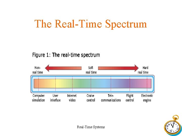
The Real-Time Spectrum Real-Time Systems
Real-Time Design Issues • How many things are under control? • How “hard” are the timing constraints? • Will there be user interaction? • What is the mix of synchronous vs. asynchronous threads of control? Real-Time Systems
Real-Time Design Approaches • There are two primary techniques used in real-time designs - Super- loops One program running -Multitasking Many programs running, taking turns Real-Time Systems
Super-Loops • Also called Foreground/Background Systems • There is a background loop that is always running anytime an ISR isn’t executing • The CPU is always busy • Can be taken to the extreme of an idle loop and all of the work being done in the ISRs Real-Time Systems
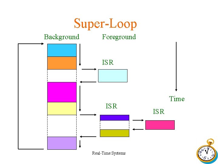
Super-Loop Background Foreground ISR Real-Time Systems Time ISR
Multi-Tasking Operation • With multi- tasking, multiple tasks or threads compete for the CPU based on a scheduling policy • This scheduling policy is implemented in the Kernel • The tasks give up the CPU: -Voluntarily: cooperative multi- tasking Developer determined via system call - Involuntarily: preemptive multi- tasking Process scheduling algorithm Real-Time Systems
Multi-Tasking Real-Time Systems
Session 2 Real-Time Operating Systems Real-Time Systems
What Is An RTOS? • A Real- Time Operating System is software that allows a program to: – Communicate with peripherals and other tasks – React in a deterministic way to external events – Share the CPU and resources in a rigidly established manner between competing threads of execution Real-Time Systems
Commercial RTOSs • • • Vx. Works p. SOS System QNX Nucleus Windows CE Mirco. C/OS-II Real-Time Systems
Commercial RTOS Shortcomings • Can be very expen$ive • High, per- seat costs • Royalties • Access to source Real-Time Systems
Free RTOSs • • • Embedded Linux Real-Time Linux RTAI RTEMS e. COS Real-Time Systems
Multi-Tasking Revisited • Multitasking is the process of scheduling and switching the CPU between several tasks • Maximizes the utilization of the CPU • Facilitates modular construction of applications • Simplifies the design of application programs Real-Time Systems
Task • A task (thread) is a simple program that thinks it has the CPU all to itself. • A Real-Time application consists of several tasks executing concurrently. • Each task is assigned a priority, its own set of CPU registers, and its own stack area. Real-Time Systems
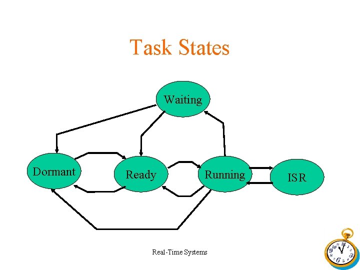
Task States Waiting Dormant Ready Running Real-Time Systems ISR
Context Switch • Occurs when a Multi-Tasking kernel decides to run a different task. • Steps involved in a context switch 1. Save current task’s context(CPU registers) in the current tasks context storage area(it’s stack) 2. Restore the new task’s context from it’s storage area(it’s stack). 3. Resume execution of the new task’s code. Real-Time Systems
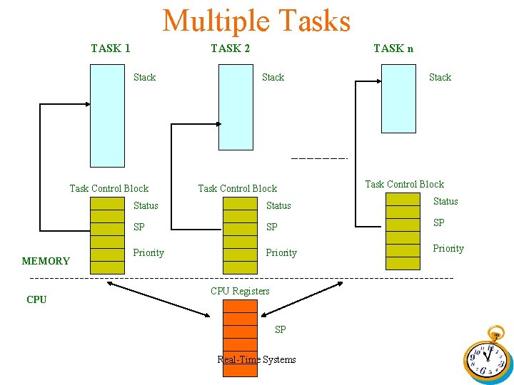
Multiple Tasks TASK 1 TASK 2 Stack Task Control Block MEMORY CPU TASK n Stack Task Control Block Status SP SP SP Priority CPU Registers SP Real-Time Systems
Kernel • Definition Kernel is the part of the multi-tasking system responsible for the management of tasks and communication between tasks. • Services - Context switching - Inter task communication services(Semaphore management, mail boxes, queues, time delays, etc. ) Real-Time Systems
Scheduler • Scheduler is the part of the kernel responsible for determining which task will run next • Most real-time kernels are priority based • Each task is assigned a priority based on its importance • The priority of each task is application specific • Control is always given to the highest priority task ready to run. Real-Time Systems
Kernel There are two types of priority based kernels • • Non-Preemptive Kernel Real-Time Systems
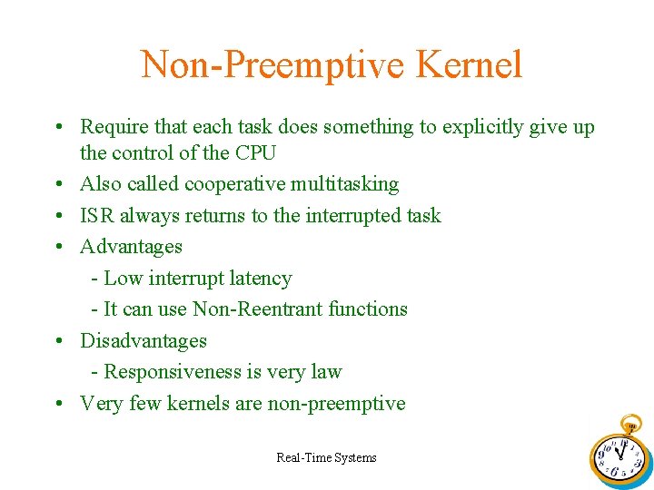
Non-Preemptive Kernel • Require that each task does something to explicitly give up the control of the CPU • Also called cooperative multitasking • ISR always returns to the interrupted task • Advantages - Low interrupt latency - It can use Non-Reentrant functions • Disadvantages - Responsiveness is very law • Very few kernels are non-preemptive Real-Time Systems
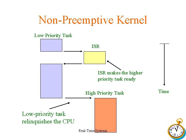
Non-Preemptive Kernel Low Priority Task ISR makes the higher priority task ready High Priority Task Low-priority task relinquishes the CPU Real-Time Systems Time
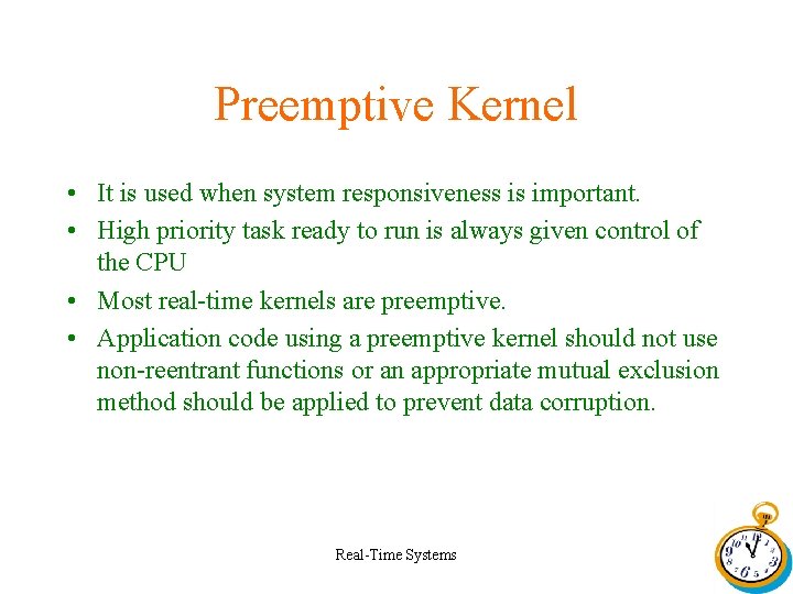
Preemptive Kernel • It is used when system responsiveness is important. • High priority task ready to run is always given control of the CPU • Most real-time kernels are preemptive. • Application code using a preemptive kernel should not use non-reentrant functions or an appropriate mutual exclusion method should be applied to prevent data corruption. Real-Time Systems
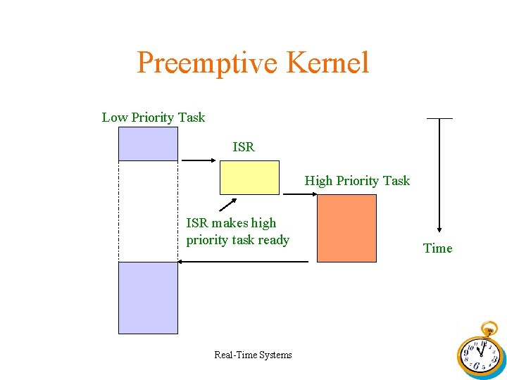
Preemptive Kernel Low Priority Task ISR High Priority Task ISR makes high priority task ready Real-Time Systems Time
Reentrancy • A reentrant function can be interrupted at any time and resumed at a later time without loss of data. • It either uses local variables or protects data when global variables are used. • It can be used by more than one task without fear of data corruption. Real-Time Systems
Mutual Exclusion • Mutual Exclusion is used to ensure the exclusive access to a shared resource without data corruption. • Common Methods are – Disabling interrupts – Disabling scheduling – Using Semaphores Real-Time Systems
Intertask Communication • Common Inter task Communication methods are 1. Message Queues 2. Mail Boxes 3. Semaphores Real-Time Systems
Session 3 Case Study TETRA Mobile Real-Time Systems
Tetra Air Interface • Tetra Systems use TDMA protocol. • TDMA defines time slots of duration 14. 167 ms • A TDMA Frame contains 4 time slots • Each time slot is a physical channel which may be used for signaling or traffic. • There is an offset of two time slots between uplink and downlink slots. Real-Time Systems
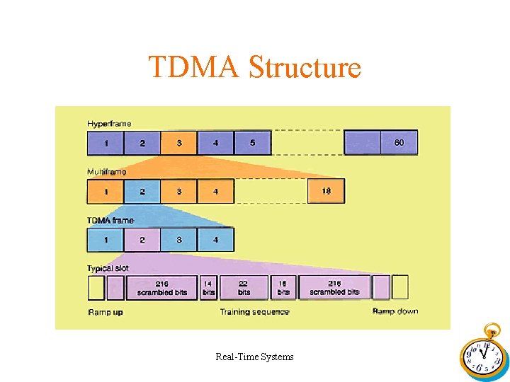
TDMA Structure Real-Time Systems
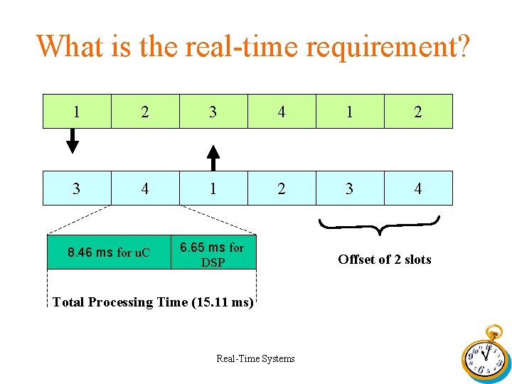
What is the real-time requirement? 1 2 3 4 8. 46 ms for u. C 6. 65 ms for DSP Total Processing Time (15. 11 ms) Real-Time Systems Offset of 2 slots
Hardware Architecture • Texas TMS 320 VC 5472 (Orion Processor) Processor • External RAM 8 MB SDRAM • Flash Memory 8 MB Real-Time Systems
Orion Processor Integrates • A DSP subsystem based on the TMS 320 C 54 x architecture and a • RISC microcontroller subsystem based on the AR 7 TDMI core. Real-Time Systems
DSP Subsystem • • Includes TMS 320 C 54 X DSP Core 74 K X 16 Bit internal SRAM ARM Port Interface Two multi channel buffered serial ports(Mc. BSPs) Timer DMA Programmable wait-state generator External Memory Interface Real-Time Systems
MCU Subsystem • ARM 7 TDMI Core • Memory interface for external SRAM, Flash, ROM and SDRAM. • On-chip 16 K-byte zero wait-state SRAM. • General purpose I/Os (GPIOS), including support for an 8 x 8 keyboard. • Three Timers(Two generic, one watchdog) • Two UARTs • Interrupt Handler Subsystem Real-Time Systems
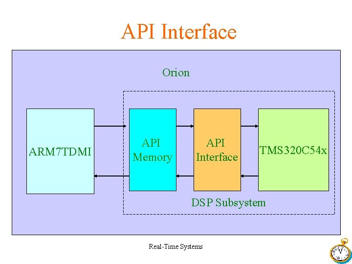
API Interface Orion ARM 7 TDMI API Memory API Interface TMS 320 C 54 x DSP Subsystem Real-Time Systems
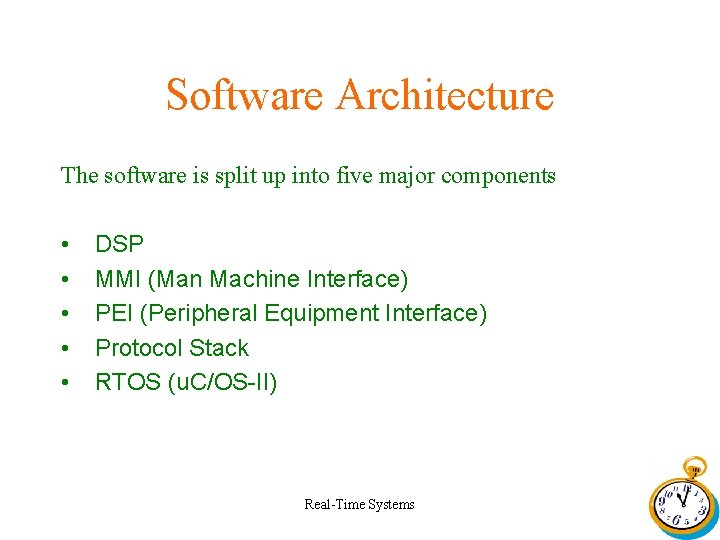
Software Architecture The software is split up into five major components • • • DSP MMI (Man Machine Interface) PEI (Peripheral Equipment Interface) Protocol Stack RTOS (u. C/OS-II) Real-Time Systems
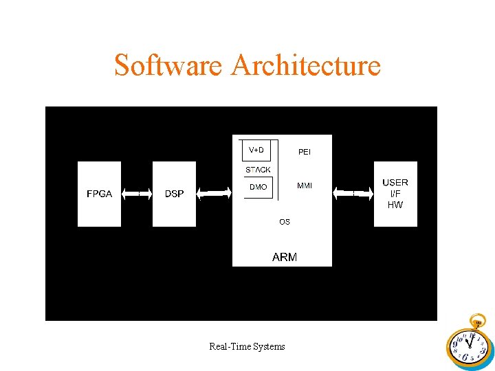
Software Architecture Real-Time Systems
ARM Software Architecture Real-Time Systems
u. C/OS-II is a real-time operating system developed by Jean J. Labrosse. • • Characteristics Preemptive Multi-tasking Romable Scalable Real-Time Systems
u. COS-II • • • Maximum number of Tasks is 64 Task priority levels can be 4 – 56 Task priority should be unique. Supports fixed block memory management. Supports Inter task communication methods such as Message Queues, Mail Boxes etc. Real-Time Systems
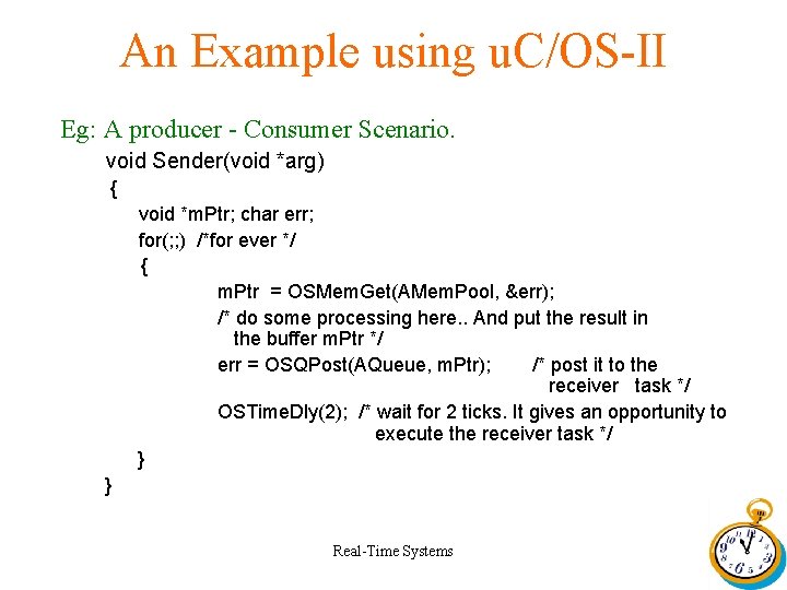
An Example using u. C/OS-II Eg: A producer - Consumer Scenario. void Sender(void *arg) { void *m. Ptr; char err; for(; ; ) /*for ever */ { m. Ptr = OSMem. Get(AMem. Pool, &err); /* do some processing here. . And put the result in the buffer m. Ptr */ err = OSQPost(AQueue, m. Ptr); /* post it to the receiver task */ OSTime. Dly(2); /* wait for 2 ticks. It gives an opportunity to execute the receiver task */ } } Real-Time Systems
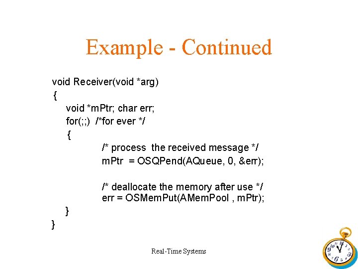
Example - Continued void Receiver(void *arg) { void *m. Ptr; char err; for(; ; ) /*for ever */ { /* process the received message */ m. Ptr = OSQPend(AQueue, 0, &err); /* deallocate the memory after use */ err = OSMem. Put(AMem. Pool , m. Ptr); } } Real-Time Systems
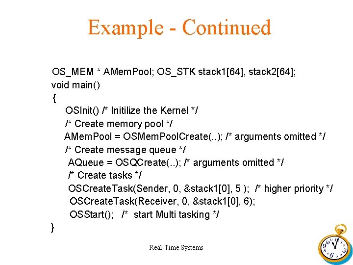
Example - Continued OS_MEM * AMem. Pool; OS_STK stack 1[64], stack 2[64]; void main() { OSInit() /* Initilize the Kernel */ /* Create memory pool */ AMem. Pool = OSMem. Pool. Create(. . ); /* arguments omitted */ /* Create message queue */ AQueue = OSQCreate(. . ); /* arguments omitted */ /* Create tasks */ OSCreate. Task(Sender, 0, &stack 1[0], 5 ); /* higher priority */ OSCreate. Task(Receiver, 0, &stack 1[0], 6); OSStart(); /* start Multi tasking */ } Real-Time Systems
SDL • Specification and Description Language(SDL) is the best suited language for developing telecommunication Protocols. • It is a graphical language. • It uses a state machine approach for developing applications Real-Time Systems
Telelogic Tau SDL Suit • A graphical Tool Set for SDL Development • Tools for Simulating the system under development. • Automatic Code generation is supported using CAdvanced SDL to C compiler. Real-Time Systems
Structure of a Telelogic SDL Application Having three parts • The SDL system. • The physical environment of the system. • The environment functions, where you connect the SDL system with the environment of the system. Real-Time Systems
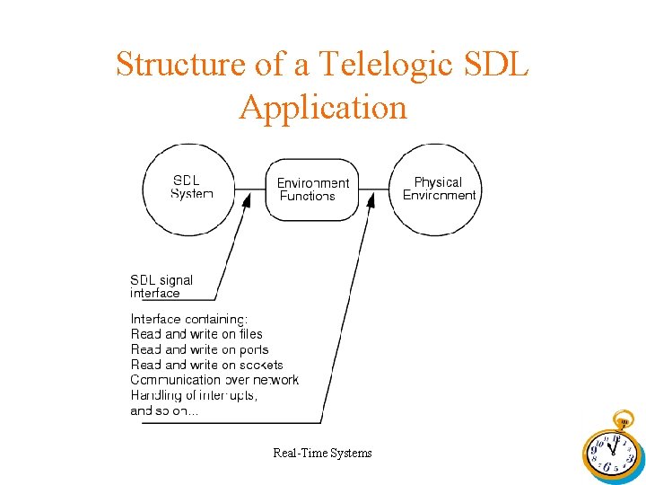
Structure of a Telelogic SDL Application Real-Time Systems
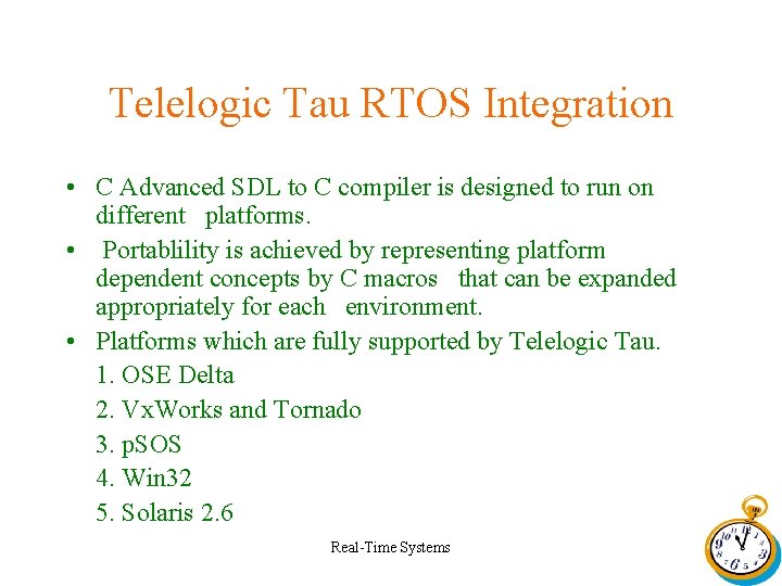
Telelogic Tau RTOS Integration • C Advanced SDL to C compiler is designed to run on different platforms. • Portablility is achieved by representing platform dependent concepts by C macros that can be expanded appropriately for each environment. • Platforms which are fully supported by Telelogic Tau. 1. OSE Delta 2. Vx. Works and Tornado 3. p. SOS 4. Win 32 5. Solaris 2. 6 Real-Time Systems
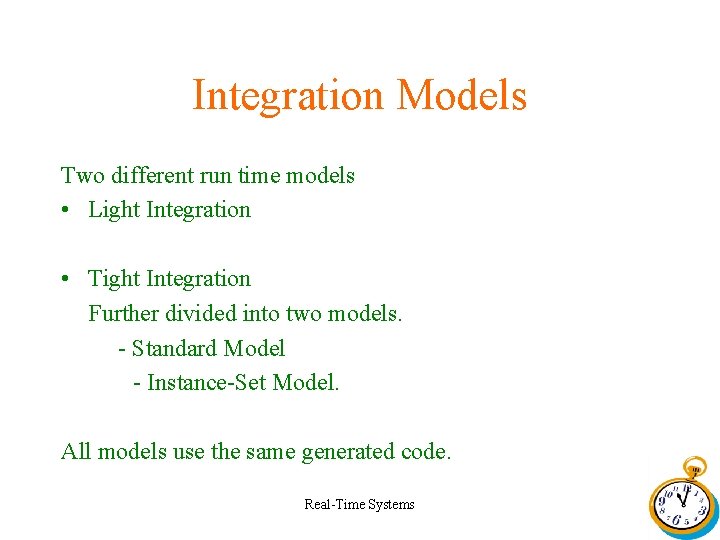
Integration Models Two different run time models • Light Integration • Tight Integration Further divided into two models. - Standard Model - Instance-Set Model. All models use the same generated code. Real-Time Systems
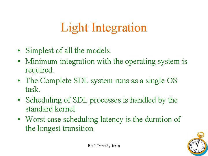
Light Integration • Simplest of all the models. • Minimum integration with the operating system is required. • The Complete SDL system runs as a single OS task. • Scheduling of SDL processes is handled by the standard kernel. • Worst case scheduling latency is the duration of the longest transition Real-Time Systems
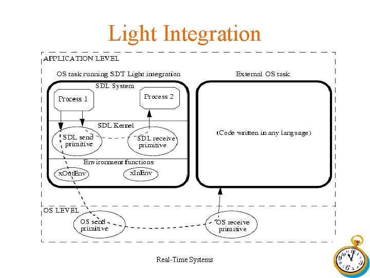
Light Integration Real-Time Systems
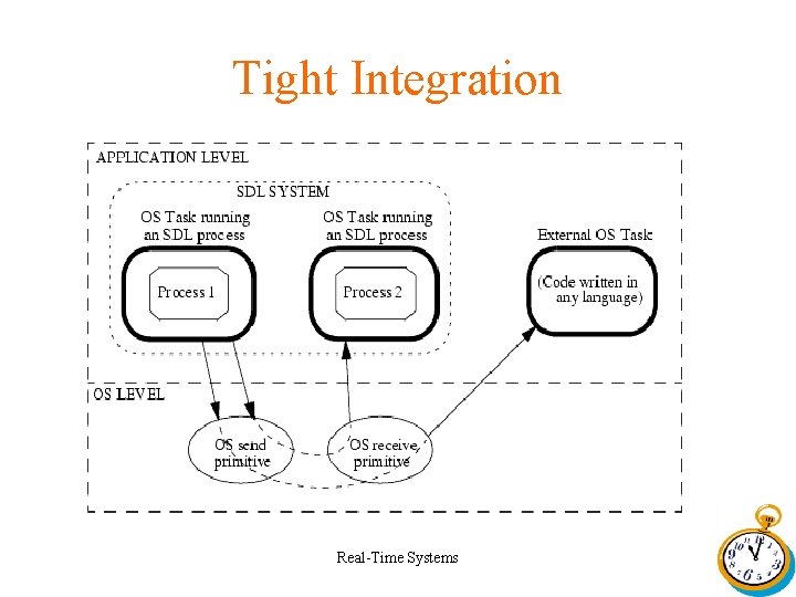
Tight Integration • The generated code interacts directly with the underlying operating system when creating processes, sending signals, etc. • The SDL processes run as separate OS tasks • Scheduling is handled by the OS and is normally timesliced, priority based and preemptive. • Communication takes place using the inter-process communications mechanisms offered by the OS, normally message queues. • There are no environment functions Real-Time Systems
Tight Integration • In the standard model of the Tight integration each SDL process is implemented as OS task. • The the Instance Set Model of the Tight integration each SDL process INSTANCE is implemented as OS task. Real-Time Systems
Tight Integration Real-Time Systems
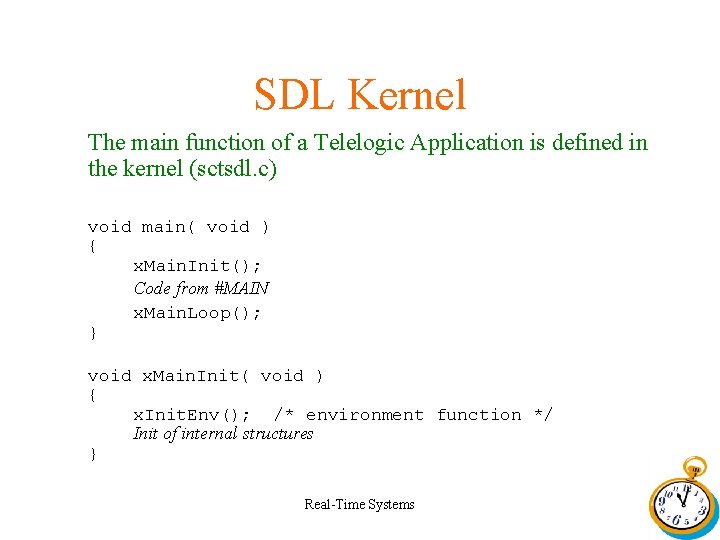
SDL Kernel The main function of a Telelogic Application is defined in the kernel (sctsdl. c) void main( void ) { x. Main. Init(); Code from #MAIN x. Main. Loop(); } void x. Main. Init( void ) { x. Init. Env(); /* environment function */ Init of internal structures } Real-Time Systems
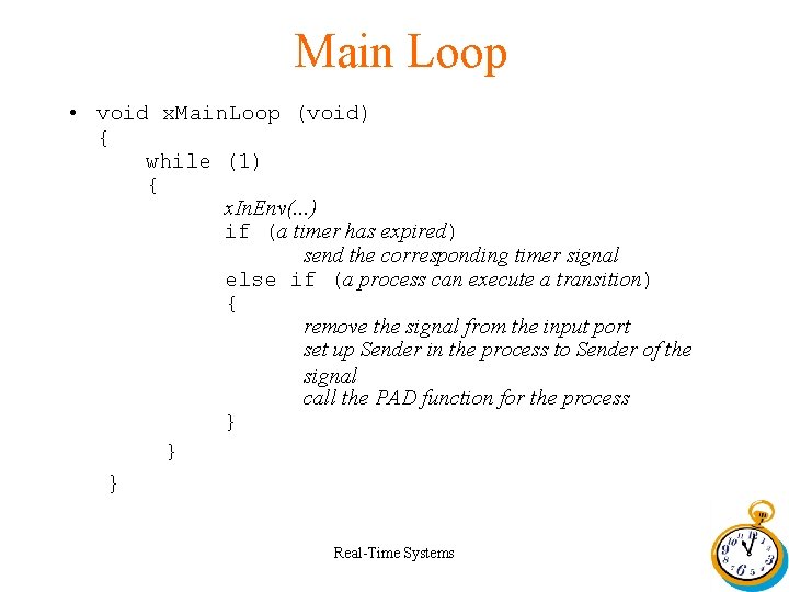
Main Loop • void x. Main. Loop (void) { while (1) { x. In. Env(. . . ) if (a timer has expired) send the corresponding timer signal else if (a process can execute a transition) { remove the signal from the input port set up Sender in the process to Sender of the signal call the PAD function for the process } } } Real-Time Systems
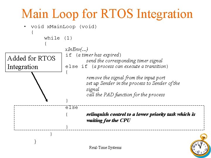
Main Loop for RTOS Integration • void x. Main. Loop (void) { while (1) { x. In. Env(. . . ) if (a timer has expired) Added for RTOS send the corresponding timer signal else if (a process can execute a transition) Integration { remove the signal from the input port set up Sender in the process to Sender of the signal call the PAD function for the process } else { relinquish control to a lower priority task which is waiting for the CPU } } } Real-Time Systems
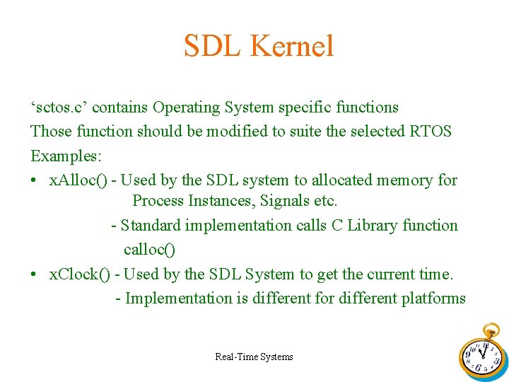
SDL Kernel ‘sctos. c’ contains Operating System specific functions Those function should be modified to suite the selected RTOS Examples: • x. Alloc() - Used by the SDL system to allocated memory for Process Instances, Signals etc. - Standard implementation calls C Library function calloc() • x. Clock() - Used by the SDL System to get the current time. - Implementation is different for different platforms Real-Time Systems
Task Level Design Tasks ISRs in the order of task priority • • API_Isr (ISR) Protocol. Stack (Task) MMI (Task) PEI (Task) Real-Time Systems
Message Queues • Message Queues are used for inter task communication • Message Queues used are PS_PDU_Queue (Protocol Stack Input) MMI_PDU_Queue (MMI task Input) PEI_PDU_Queue (PEI task Input) Real-Time Systems
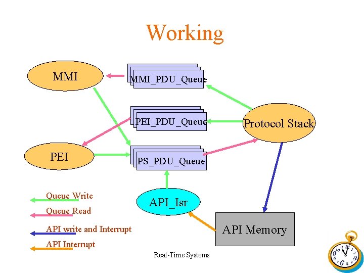
Working MMI_PDU_Queue PEI Queue Write Queue Read Protocol Stack PS_PDU_Queue API_Isr API Memory API write and Interrupt API Interrupt Real-Time Systems
Real-Time Systems
- Slides: 72