
Rendering Reconstructing Under Complex BRDFs AGENDA n Introduction
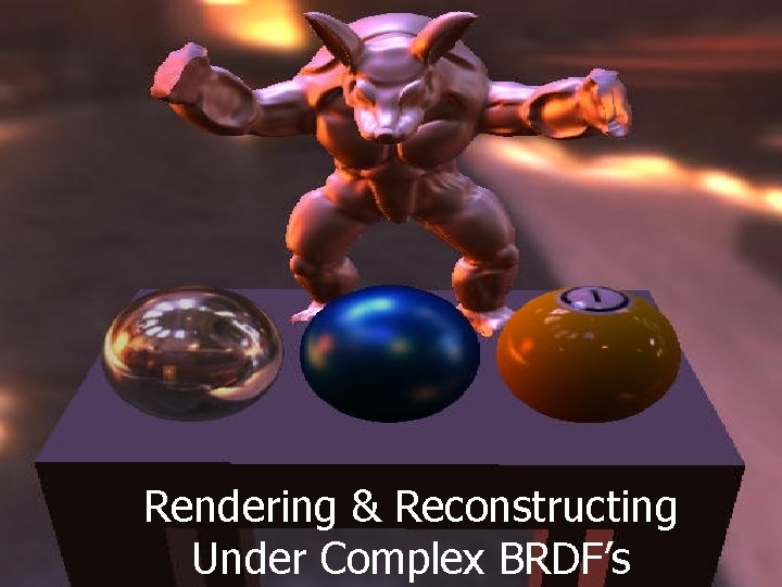
Rendering & Reconstructing Under Complex BRDF’s
AGENDA n Introduction n n Motivation Basic concepts n Photometric Stereo n Image Based Rendering (IBR) n Summary
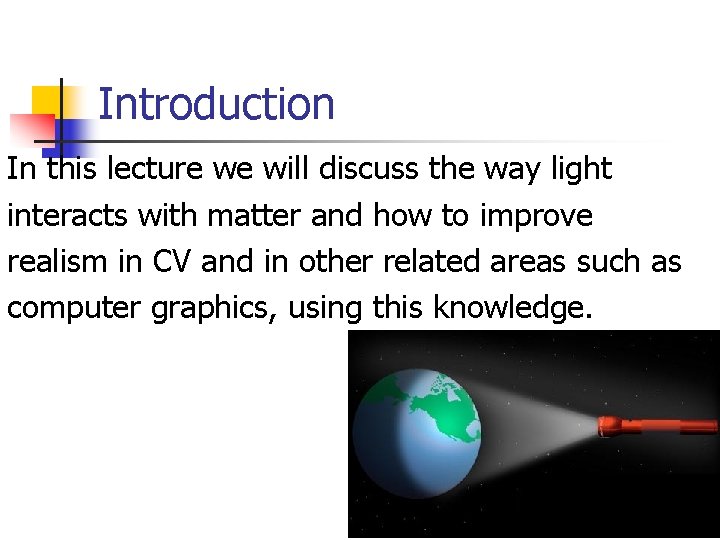
Introduction In this lecture we will discuss the way light interacts with matter and how to improve realism in CV and in other related areas such as computer graphics, using this knowledge.
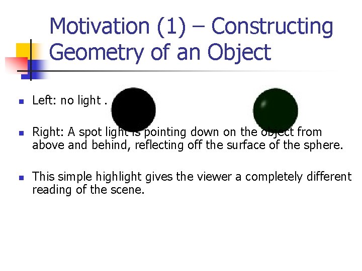
Motivation (1) – Constructing Geometry of an Object n n n Left: no light. Right: A spot light is pointing down on the object from above and behind, reflecting off the surface of the sphere. This simple highlight gives the viewer a completely different reading of the scene.
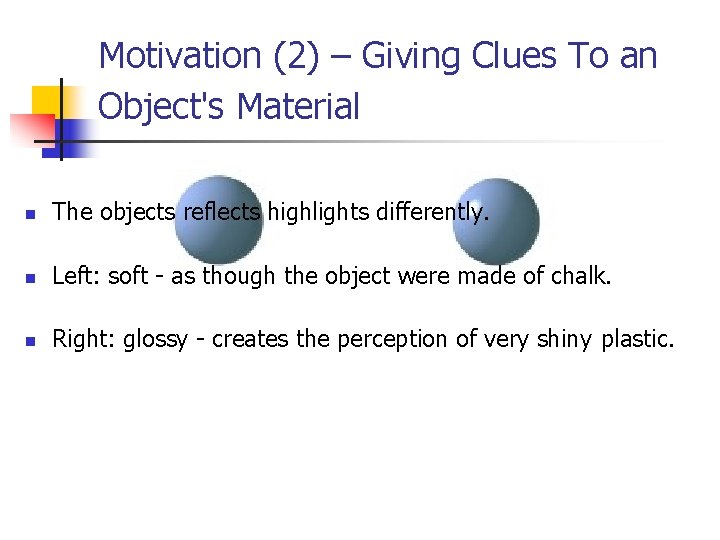
Motivation (2) – Giving Clues To an Object's Material n The objects reflects highlights differently. n Left: soft - as though the object were made of chalk. n Right: glossy - creates the perception of very shiny plastic.
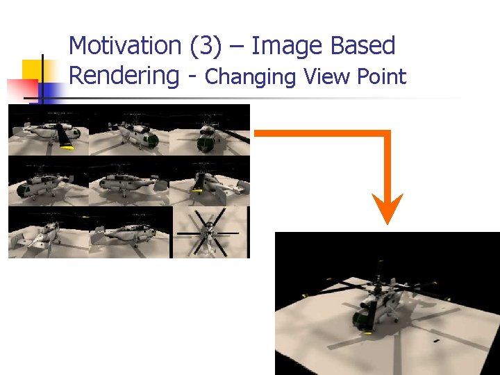
Motivation (3) – Image Based Rendering - Changing View Point
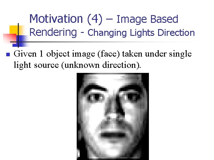
Motivation (4) – Image Based Rendering - Changing Lights Direction n Given 1 object image (face) taken under single light source (unknown direction).
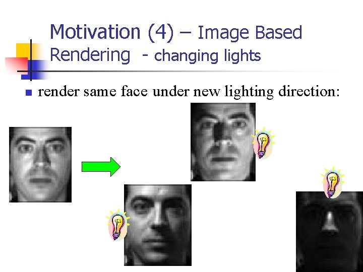
Motivation (4) – Image Based Rendering - changing lights n render same face under new lighting direction:
Basic Concepts n n n n n Radiometry Solid angle Radiance Irradiance Radiosity & Exitance BRDF “Helmholtz” Reciprocity Rule Isotropic vs. Anisotropic Special BRDF n n n Diffuse surface & Lambertian Low Specular surface & Fong Model Local vs. Global Illumination
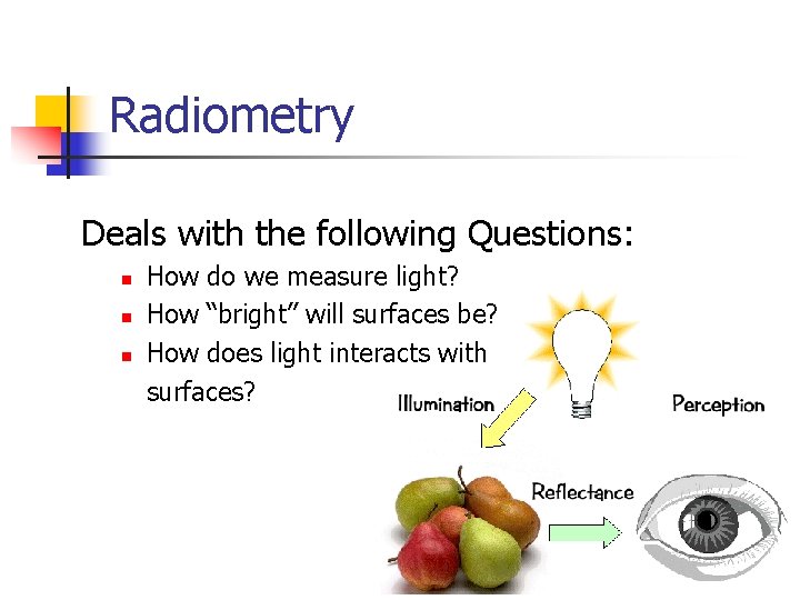
Radiometry Deals with the following Questions: How do we measure light? n How “bright” will surfaces be? n How does light interacts with surfaces? n
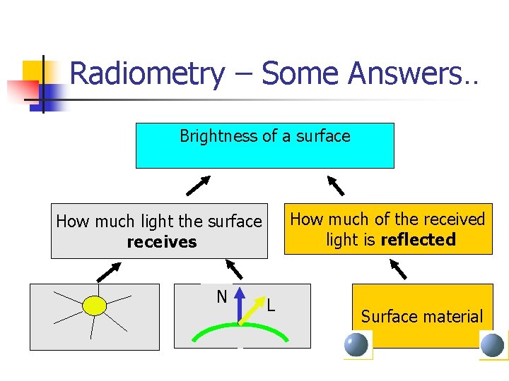
Radiometry – Some Answers. . Brightness of a surface How much of the received light is reflected How much light the surface receives N L Surface material
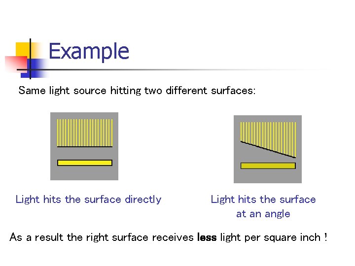
Example Same light source hitting two different surfaces: Light hits the surface directly Light hits the surface at an angle As a result the right surface receives less light per square inch !
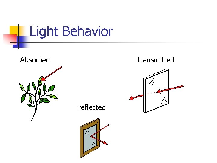
Light Behavior Absorbed transmitted reflected
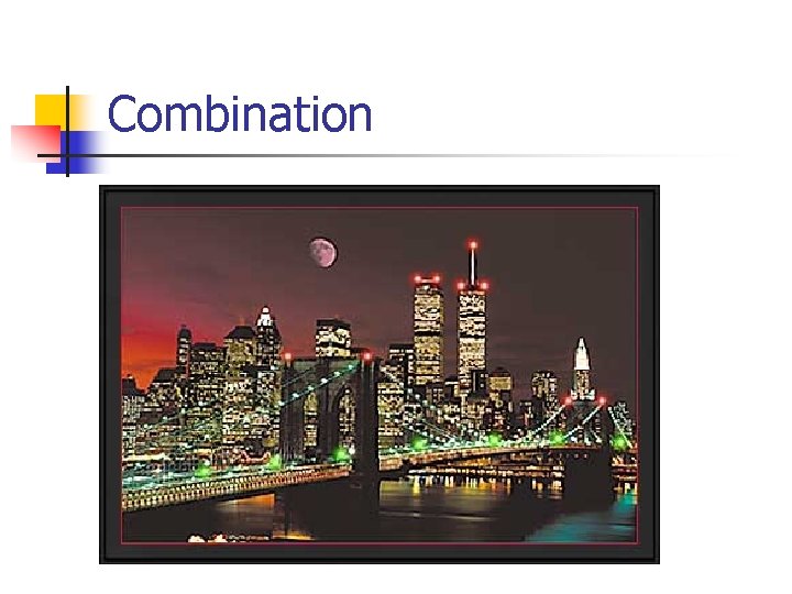
Combination
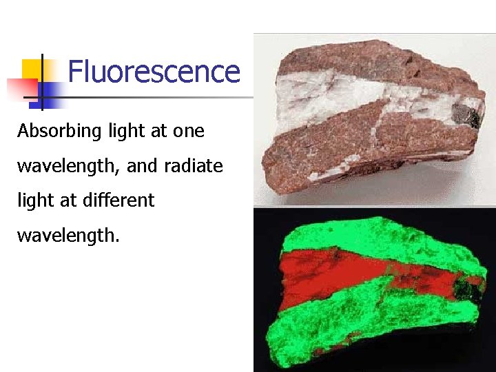
Fluorescence Absorbing light at one wavelength, and radiate light at different wavelength.
Simplifying Assumptions n n n The light leaving a point on a surface is due only to light arriving at this point. No Fluorescence Surfaces do not generate light internally - treating sources separately.
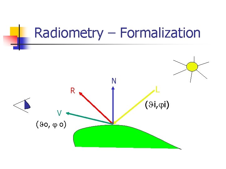
Radiometry – Formalization N R V ( o, o) L ( i, i)
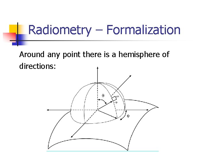
Radiometry – Formalization Around any point there is a hemisphere of directions:
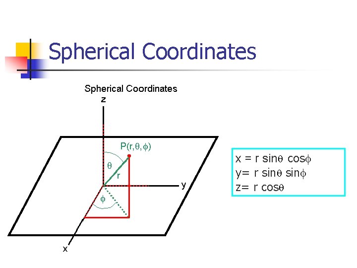
Spherical Coordinates x = r sin cos y= r sin z= r cos
Basic Concepts n n n n n Radiometry Solid angle Radiance Irradiance Radiosity & Exitance BRDF “Helmholtz” Reciprocity Rule Isotropic vs. Anisotropic Special BRDF n n n Diffuse surface & Lambertian Low Specular surfac & Fong Model Local vs. Global Illumination
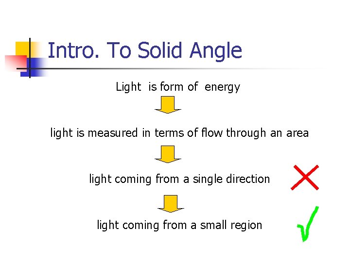
Intro. To Solid Angle Light is form of energy light is measured in terms of flow through an area light coming from a single direction light coming from a small region
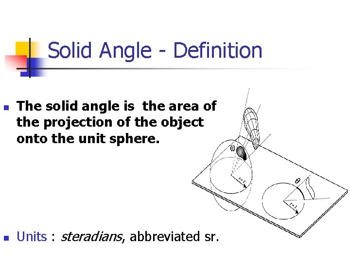
Solid Angle - Definition n n The solid angle is the area of the projection of the object onto the unit sphere. Units : steradians, abbreviated sr.
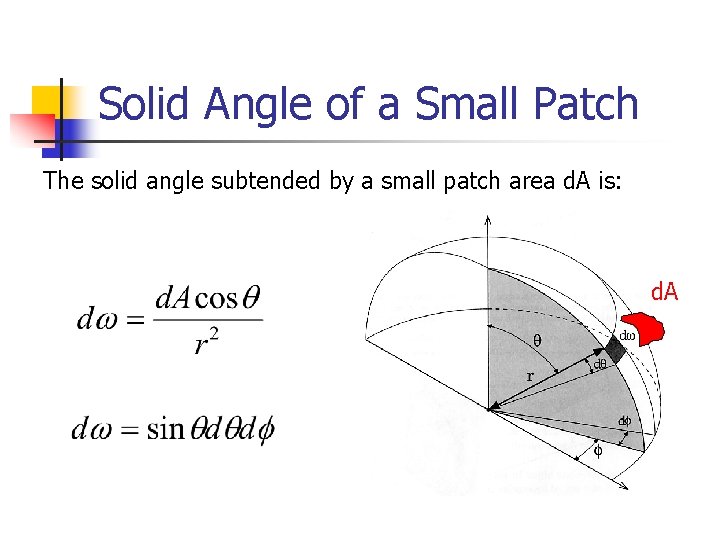
Solid Angle of a Small Patch The solid angle subtended by a small patch area d. A is: d. A
Basic Concepts n n n n Radiometry Solid angle Radiance & Irradiance Radiosity & Exitance BRDF “Helmholtz” Reciprocity Rule Isotropic vs. Anisotropic Special BRDF n n n Diffuse surface & Lambertian Low Specular surfac & Fong Model Local vs. Global Illumination
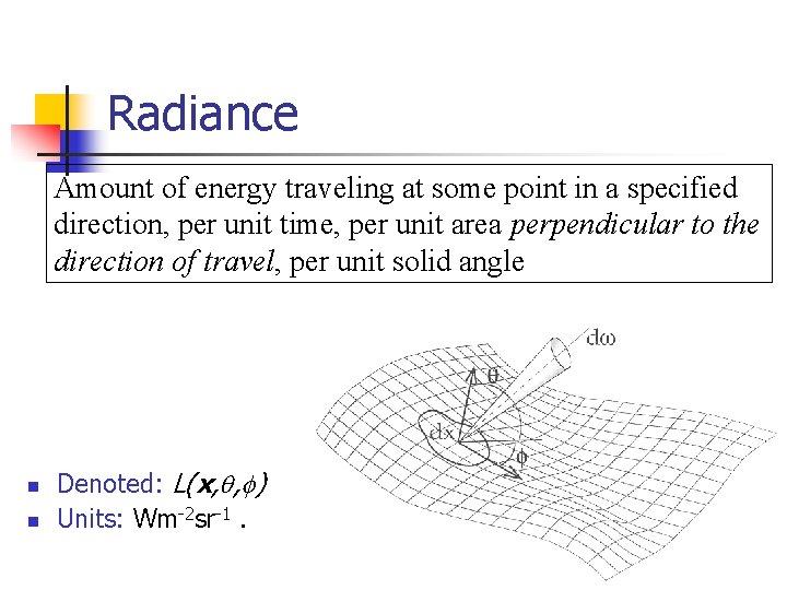
Radiance Amount of energy traveling at some point in a specified direction, per unit time, per unit area perpendicular to the direction of travel, per unit solid angle n n Denoted: L(x, , ) Units: Wm-2 sr-1.
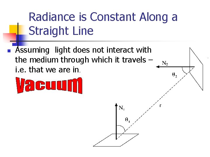
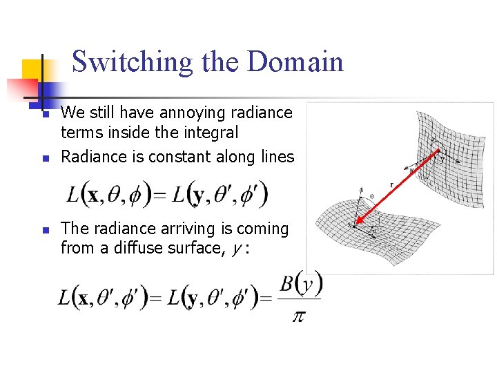
Radiance is Constant Along a Straight Line n Assuming light does not interact with the medium through which it travels – i. e. that we are in.
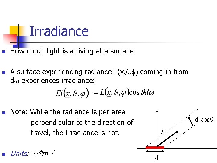
Irradiance n n How much light is arriving at a surface. A surface experiencing radiance L(x, , ) coming in from dw experiences irradiance: Note: While the radiance is per area perpendicular to the direction of travel, the Irradiance is not. Units: W*m -2 d cos d
Basic Concepts n n n n n Radiometry Solid angle Radiance Irradiance Radiosity & Exitance BRDF “Helmholtz” Reciprocity Rule Isotropic vs. Anisotropic Special BRDF n n n Diffuse surface & Lambertian Low Specular surfac & Fong Model Local vs. Global Illumination
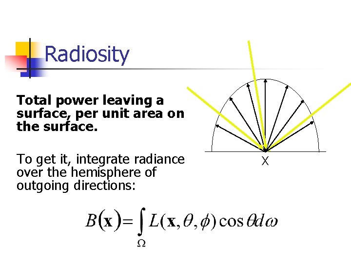
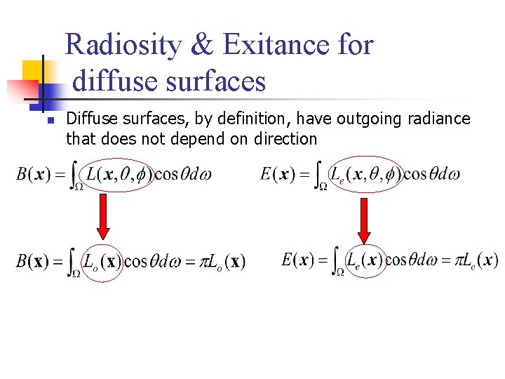
Radiosity Total power leaving a surface, per unit area on the surface. To get it, integrate radiance over the hemisphere of outgoing directions: X
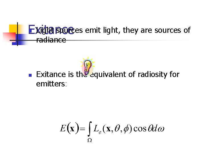
Light sources emit light, they are sources of Exitance n radiance n Exitance is the equivalent of radiosity for emitters:
Basic Concepts n n n n n Radiometry Solid angle Radiance Irradiance Radiosity & Exitance BRDF “Helmholtz” Reciprocity Rule Isotropic vs. Anisotropic Special BRDF n n n Diffuse surface & Lambertian Low Specular surfac & Fong Model Local vs. Global Illumination
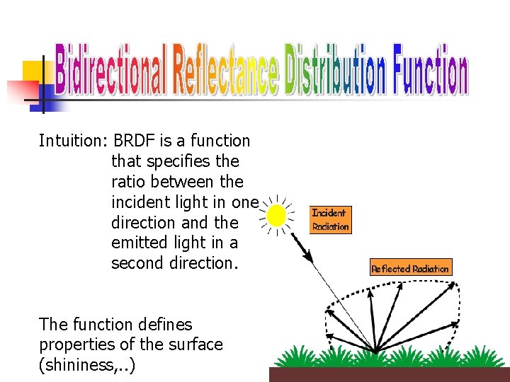
Intuition: BRDF is a function that specifies the ratio between the incident light in one direction and the emitted light in a second direction. The function defines properties of the surface (shininess, . . )
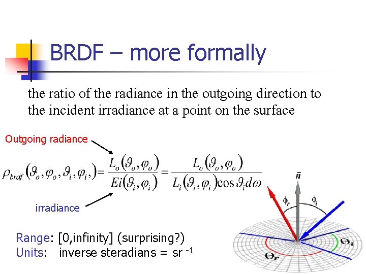
BRDF – more formally the ratio of the radiance in the outgoing direction to the incident irradiance at a point on the surface Outgoing radiance irradiance Range: [0, infinity] (surprising? ) Units: inverse steradians = sr -1
Basic Concepts n n n n n Radiometry Solid angle Radiance Irradiance Radiosity & Exitance BRDF “Helmholtz” Reciprocity Rule Isotropic vs. Anisotropic Special BRDF n n n Diffuse surface & Lambertian Low Specular surfac & Fong Model Local vs. Global Illumination
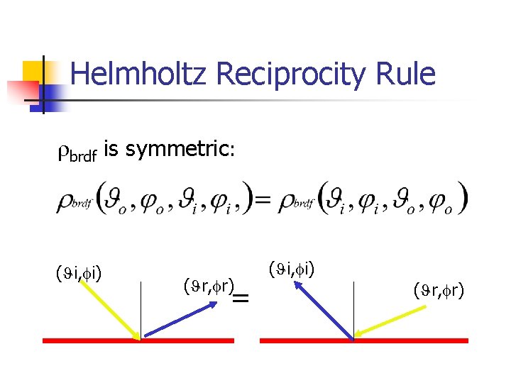
Helmholtz Reciprocity Rule brdf is symmetric: ( i, i) ( r, r) = ( i, i) ( r, r)
Basic Concepts n n n n n Radiometry Solid angle Radiance Irradiance Radiosity & Exitance BRDF “Helmholtz” Reciprocity Rule Isotropic vs. Anisotropic Special BRDF n n n Diffuse surface & Lambertian Low Specular surfac & Fong Model Local vs. Global Illumination
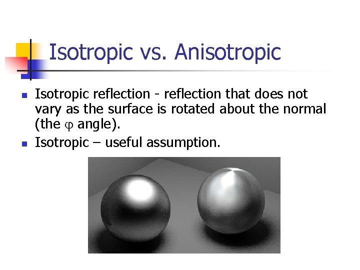
Isotropic vs. Anisotropic n n Isotropic reflection - reflection that does not vary as the surface is rotated about the normal (the angle). Isotropic – useful assumption.
Basic Concepts n n n n n Radiometry Solid angle Radiance Irradiance Radiosity & Exitance BRDF “Helmholtz” Reciprocity Rule Isotropic vs. Anisotropic Special BRDF n n n Diffuse surface & Lambertian Low Specular surfac & Fong Model Local vs. Global Illumination
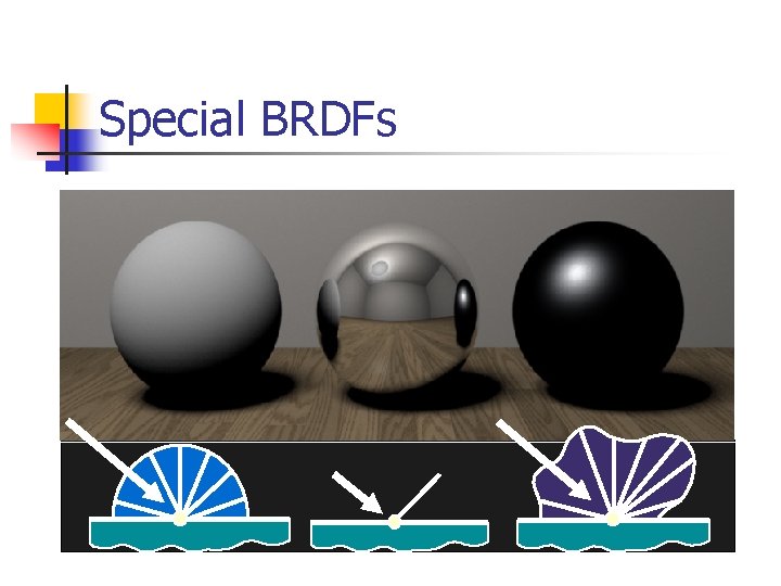
Special BRDFs
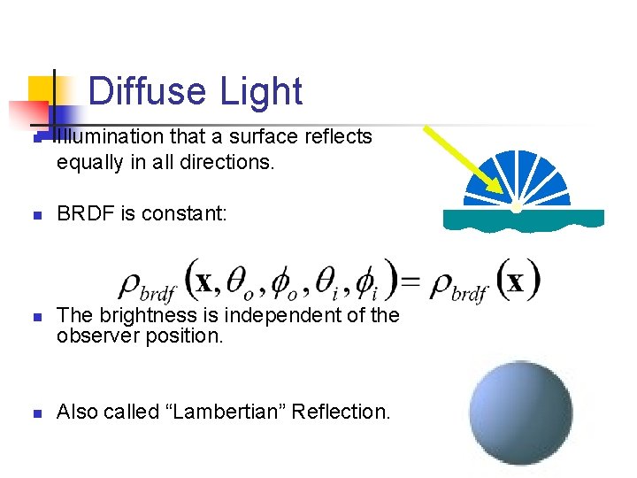
Diffuse Light n n Illumination that a surface reflects equally in all directions. BRDF is constant: The brightness is independent of the observer position. Also called “Lambertian” Reflection.
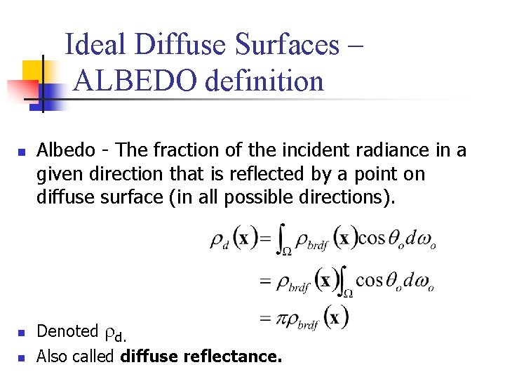
Ideal Diffuse Surfaces – ALBEDO definition n Albedo - The fraction of the incident radiance in a given direction that is reflected by a point on diffuse surface (in all possible directions). Denoted d. Also called diffuse reflectance.
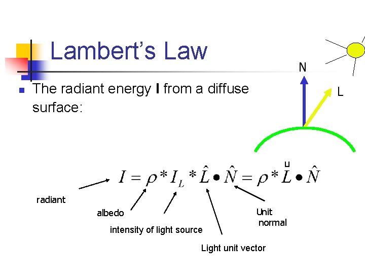
Lambert’s Law n N The radiant energy I from a diffuse surface: L radiant albedo intensity of light source Unit normal Light unit vector
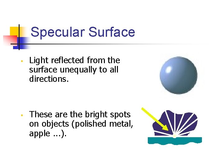
Specular Surface § § Light reflected from the surface unequally to all directions. These are the bright spots on objects (polished metal, apple. . . ).
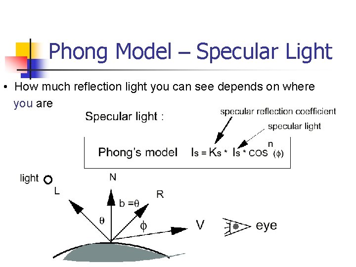
Phong Model – Specular Light • How much reflection light you can see depends on where you are
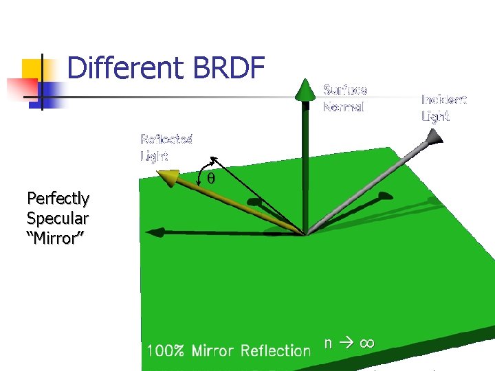
Different BRDF Perfectly Specular “Mirror” n ∞ ∞
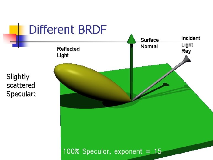
Different BRDF Reflected Light Slightly scattered Specular: Surface Normal Incident Light Ray
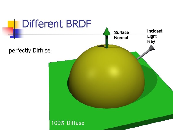
Different BRDF Surface Normal perfectly Diffuse Incident Light Ray
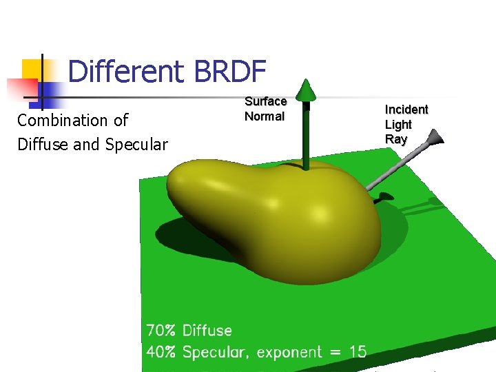
Different BRDF Combination of Diffuse and Specular Surface Normal Incident Light Ray
Basic Concepts n n n n n Radiometry Solid angle Radiance Irradiance Radiosity & Exitance BRDF “Helmholtz” Reciprocity Rule Isotropic vs. Anisotropic Special BRDF n n n Diffuse surface & Lambertian Low Specular surfac & Fong Model Local vs. Global Illumination
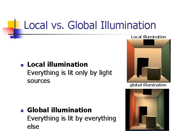
Local vs. Global Illumination Local illumination n n Local illumination Everything is lit only by light sources Global illumination Everything is lit by everything else global illumination

O. K. So Now What!?
Photometric Stereo
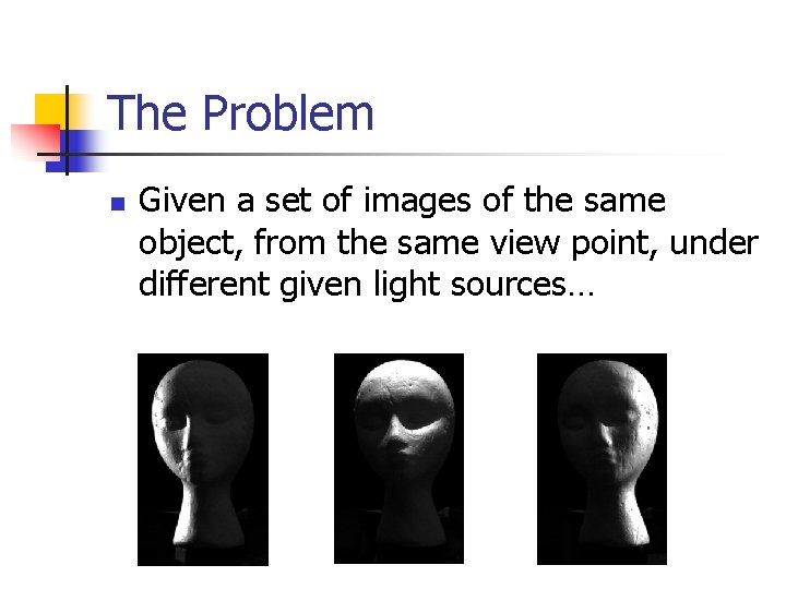
The Problem n Given a set of images of the same object, from the same view point, under different given light sources…
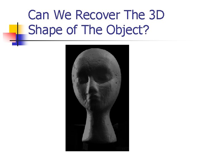
Can We Recover The 3 D Shape of The Object?
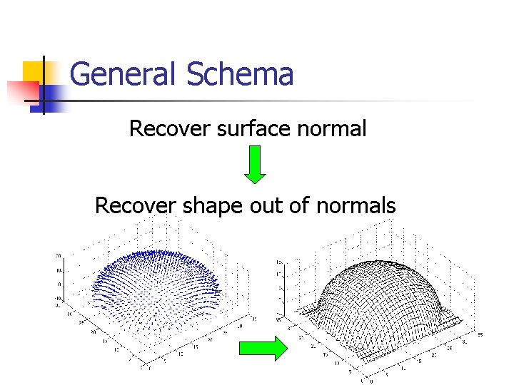
General Schema Recover surface normal Recover shape out of normals
Overview n Classic approach n n n Recover surface normal when the light is known Recover surface normal when the light is unknown New idea – “shape by example”
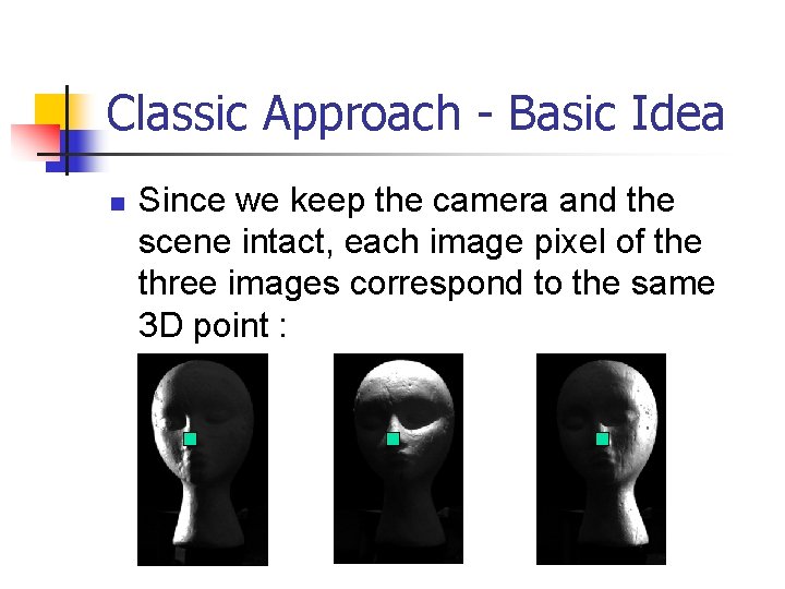
Classic Approach - Basic Idea n Since we keep the camera and the scene intact, each image pixel of the three images correspond to the same 3 D point :
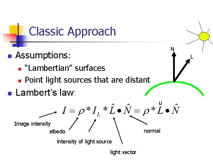
Classic Approach n Assumptions: n n n N L “Lambertian” surfaces Point light sources that are distant Lambert’s law: Image intensity albedo normal intensity of light source light vector
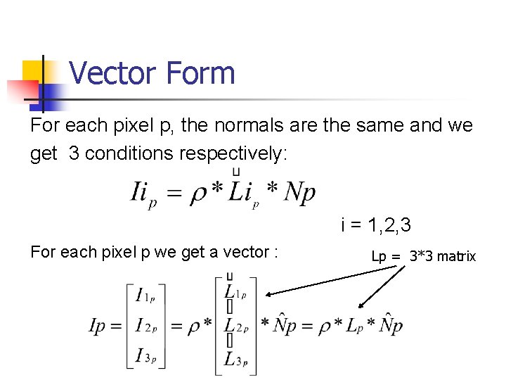
Vector Form For each pixel p, the normals are the same and we get 3 conditions respectively: i = 1, 2, 3 For each pixel p we get a vector : Lp = 3*3 matrix
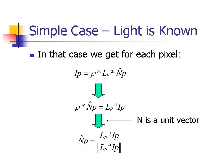
Simple Case – Light is Known n In that case we get for each pixel: N is a unit vector
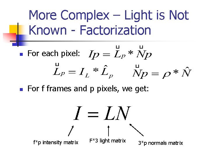
More Complex – Light is Not Known - Factorization n For each pixel: n For f frames and p pixels, we get: f*p intensity matrix F*3 light matrix 3*p normals matrix
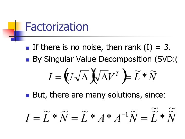
Factorization n If there is no noise, then rank (I) = 3. By Singular Value Decomposition (SVD: ( n But, there are many solutions, since: n
Shape and Materials by Example: A Photometric Stereo Approach Aaron Hertzmann, University of Toronto & Steve Seitz, University of Washington
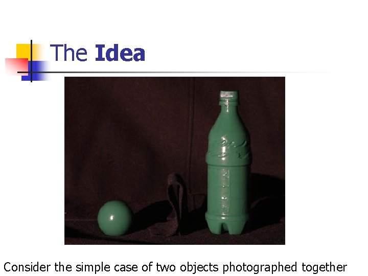
The Idea Consider the simple case of two objects photographed together
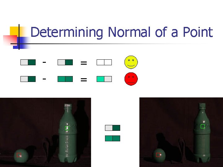
Orientation-Consistency Cue Suppose, we would like to determine the shape of the bottle. Under the right conditions it holds that: “Two points with the same surface orientation reflect the same light toward the viewer”
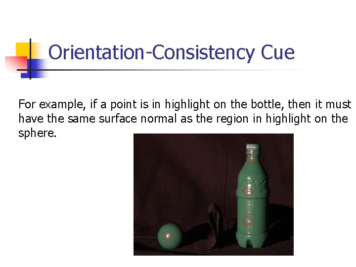
Orientation-Consistency Cue For example, if a point is in highlight on the bottle, then it must have the same surface normal as the region in highlight on the sphere.
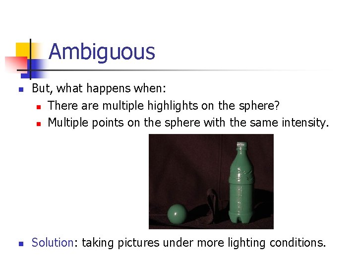
Ambiguous n n But, what happens when: n There are multiple highlights on the sphere? n Multiple points on the sphere with the same intensity. Solution: taking pictures under more lighting conditions.
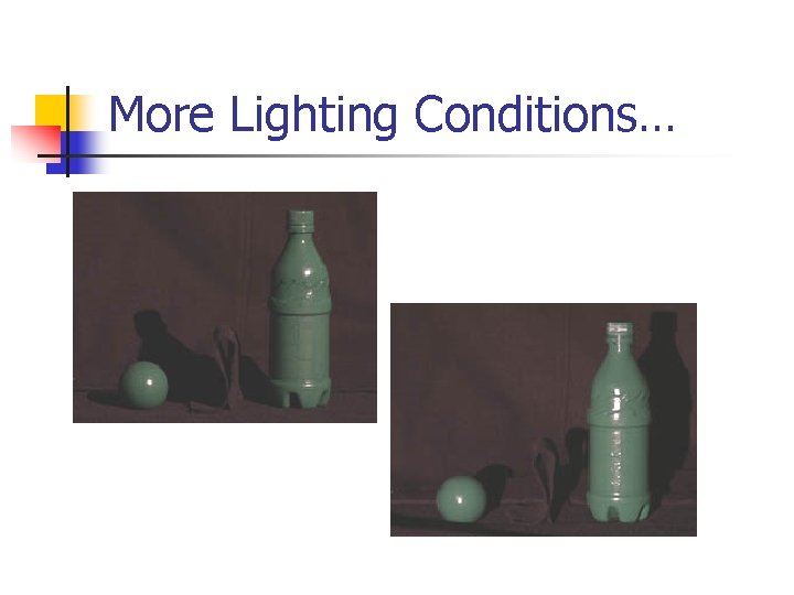
More Lighting Conditions…
General Assumptions • At least one reference object of the same or similar material must be imaged under the same illumination. • The shape of the reference object (sphere) is known. • Lighting is distant. • The camera is orthographic. • Local illumination only – shadows, intereflection and so on are ignored.
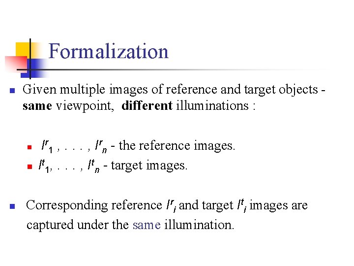
Formalization n Given multiple images of reference and target objects same viewpoint, different illuminations : n n n Ir 1 , . . . , Irn - the reference images. It 1, . . . , Itn - target images. Corresponding reference Iri and target Iti images are captured under the same illumination.
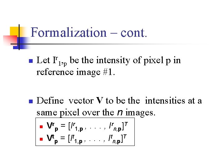
Formalization – cont. n n Let Ir 1, p be the intensity of pixel p in reference image #1. Define vector V to be the intensities at a same pixel over the n images. n n Vrp = [Ir 1, p , . . . , Irn, p]T Vtp = [It 1, p , . . . , Itn, p]T
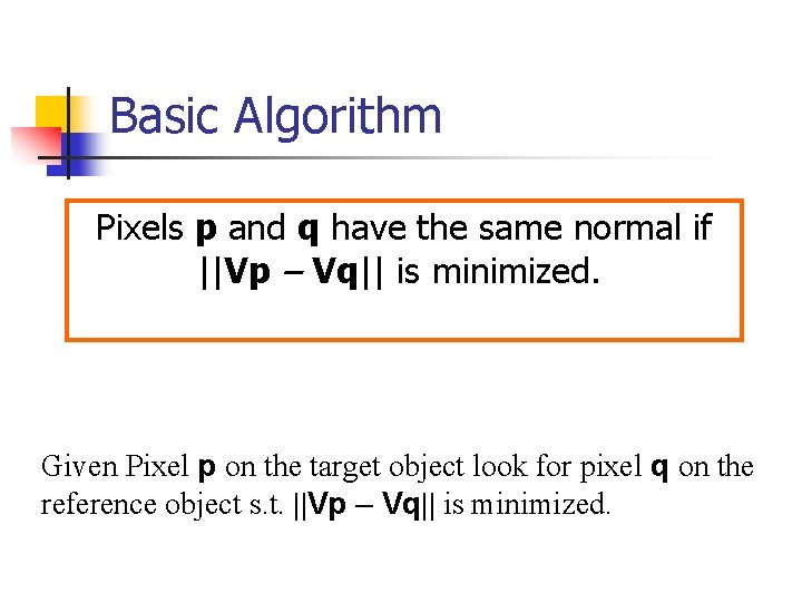
Basic Algorithm Pixels p and q have the same normal if ||Vp – Vq|| is minimized. Given Pixel p on the target object look for pixel q on the reference object s. t. ||Vp – Vq|| is minimized.
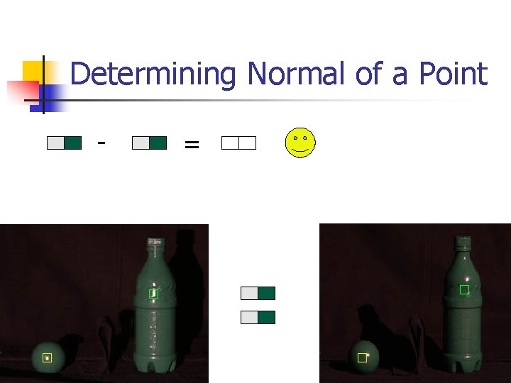
Determining Normal of a Point - =
Determining Normal of a Point - = =
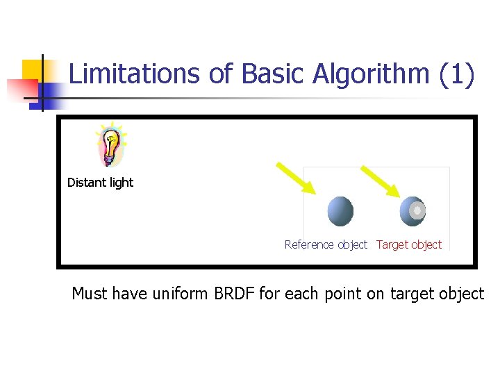
Limitations of Basic Algorithm (1) Distant light Reference object Target object Must have uniform BRDF for each point on target object
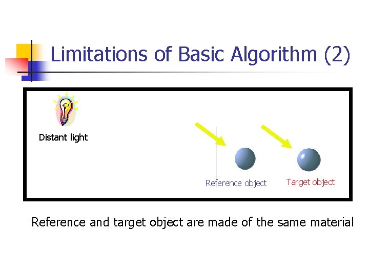
Limitations of Basic Algorithm (2) Distant light Reference object Target object Reference and target object are made of the same material
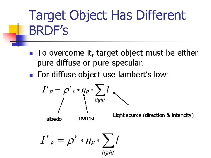
Target Object Has Different BRDF’s n n To overcome it, target object must be either pure diffuse or pure specular. For diffuse object use lambert’s low: albedo normal Light source (direction & intencity)
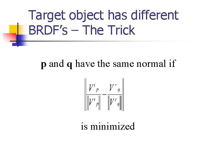
Target object has different BRDF’s – The Trick p and q have the same normal if is minimized
Target Object Made of Multiple Materials n Assume every material can be represented as linear combination of k (base) materials. n Use k (independent) reference objects. n Each pixel in target material can be represented as a linear combination of the k reference materials. n Find material coefficient and pixel q for best corresponding with pixel p.
Advantages n The BRDF may be arbitrary. n BRDF may vary over the surface. n The illumination may be unknown. n Any number of light source.
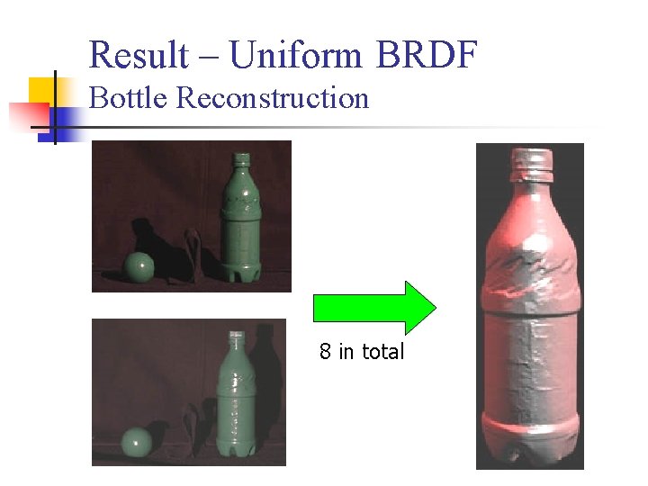
Result – Uniform BRDF Bottle Reconstruction 8 in total
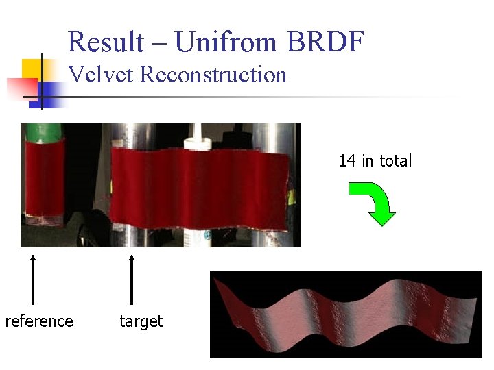
Result – Unifrom BRDF Velvet Reconstruction 14 in total reference target
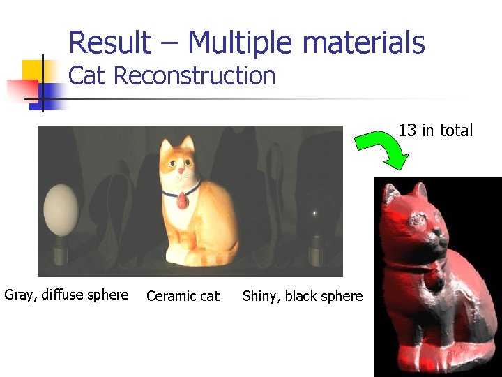
Result – Multiple materials Cat Reconstruction 13 in total Gray, diffuse sphere Ceramic cat Shiny, black sphere
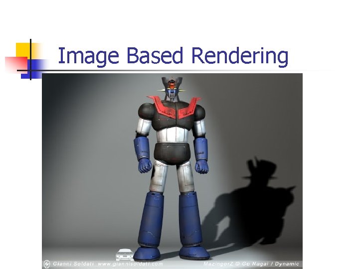
Image Based Rendering
Image Based Rendering (IBR( n Input: Dense set of images from different viewpoints or different illumination. Goal: Create pictures of synthetic scenes under new illumination conditions or from new viewpoints. n n The picture should be undistinguishable from photographs of real environments.
Rendering Algorithms Differ in the assumptions made regarding lighting and reflectance in the scene and in the solution space. n n n local vs. global illumination algorithms. view dependent vs. view independent solutions.
Agenda n n n Local illumination, view dependent algorithm for rendering a human face Global illumination, view independent algorithm for acquiring the reflectance properties of complete scenes Summary

Local Illumination View Dependent
Acquiring the Reflectance Field of a Human Face Paul Debevec, Tim Hawkins, Chris Tchou, Haarm-Pieter Duiker, Westley Sarokin, Mark Sagar SIGGRAPH 2000
Goals n n n Acquire images of the face from 2 viewpoints under a dense sampling of incident illumination directions. Construct a reflectance function for each pixel. Render the face under new illumination conditions.
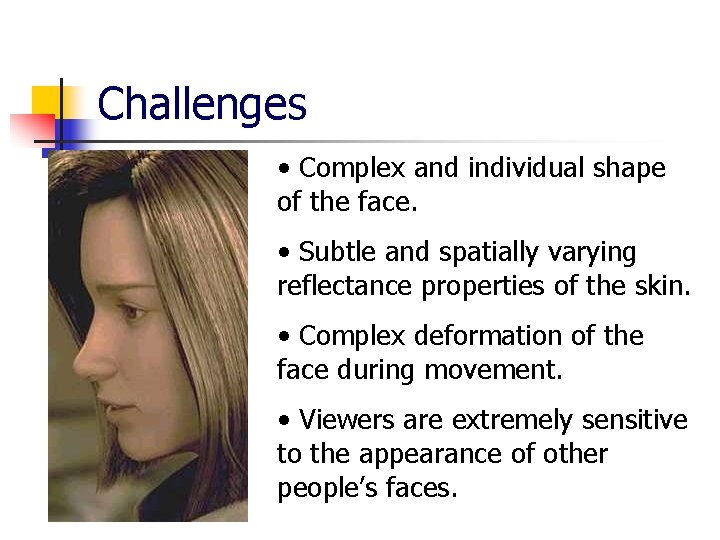
Challenges • Complex and individual shape of the face. • Subtle and spatially varying reflectance properties of the skin. • Complex deformation of the face during movement. • Viewers are extremely sensitive to the appearance of other people’s faces.
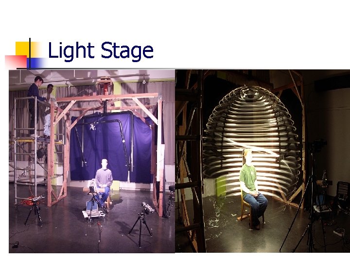
Light Stage
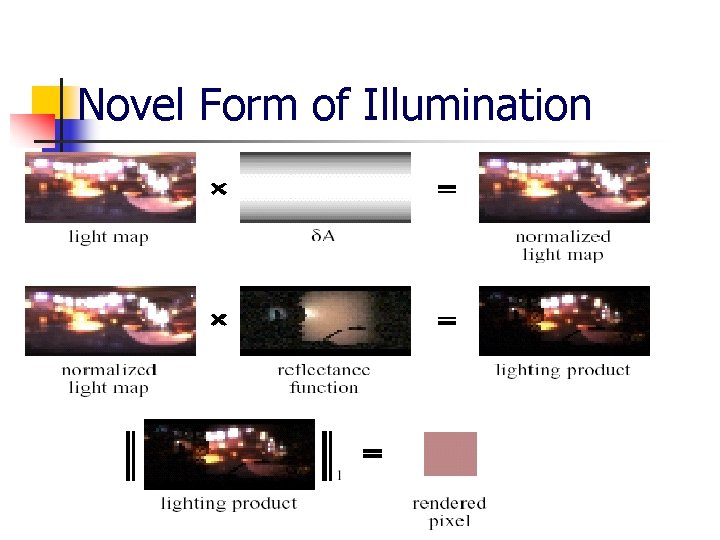
Constructing Reflectance Functions n n n For each pixel location (x, y) in each camera, that location on the face is illuminated for 64 x 32 directions of and . For each pixel we keep all radiance values under 2000 different illumination direction (reflectance function). Rxy( , ) corresponding to the ray through the pixel (x, y) with illumination direction ( , ).

Novel Form of Illumination n Rxy( , ) represents how much light is reflected towards the camera by pixel (x, y) as a result of the illumination from direction ( , ). Solid angle covered by each of the illumination directions
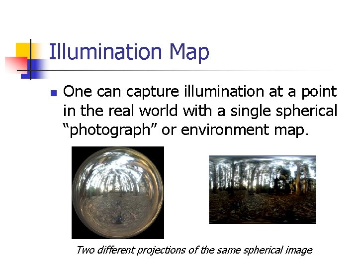
Illumination Map n One can capture illumination at a point in the real world with a single spherical “photograph” or environment map. Two different projections of the same spherical image
Novel Form of Illumination
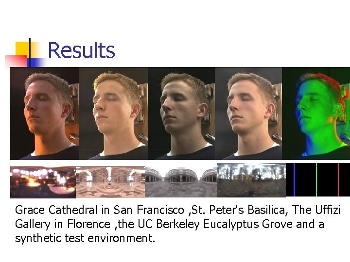
Results Grace Cathedral in San Francisco , St. Peter's Basilica, The Uffizi Gallery in Florence , the UC Berkeley Eucalyptus Grove and a synthetic test environment.
Watching a movie…
Render a human face - summary n n n 2000 images taken from a fixed viewpoint under different illumination conditions A reflectance function for each pixel was created using these images A linear combination for each pixel together with the illumination map enable rendering the face from natural illumination conditions

Global Illumination View Independent
Global illumination , view independent n Some basis n n The Global illumination equation Basic Radiosity methods n New idea – Inverse Global Illumination n Summary
Recall Radiance – Amount of light. BRDF – Ratio between out going radiance and coming irradiance. Radiosity - Total power leaving a surface. Exitance – Total power leaving a point on a light source.
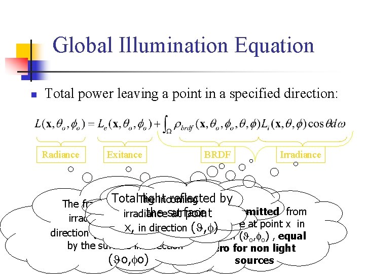
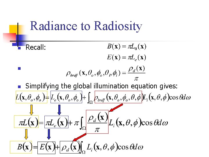
Global Illumination Equation n Total power leaving a point in a specified direction: Radiance Exitance BRDF Irradiance Total light reflected by The incoming The fraction of the incoming Radiance emitted from the surface Total radiance irradiance at point x, in the surace at point x in x, in direction ( , ) leaving the point x direction ( , ) which is reflected direction ( o, o) , equal on the surface in by the surface in direction zero for non light ) ( o, o)direction ( o, osources
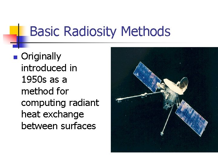
Basic Radiosity Methods n Originally introduced in 1950 s as a method for computing radiant heat exchange between surfaces
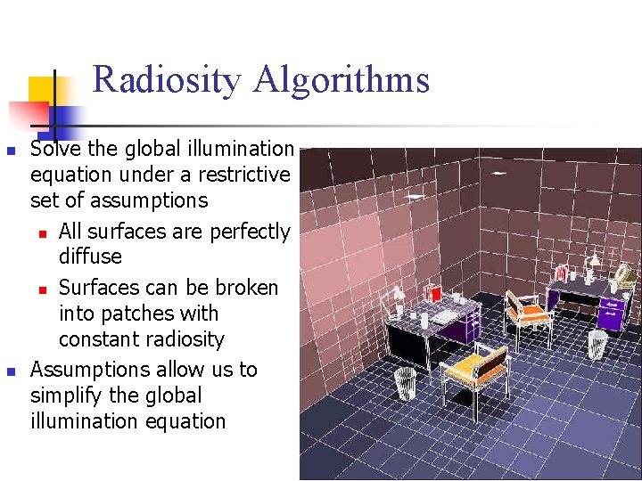
Radiosity Algorithms n n Solve the global illumination equation under a restrictive set of assumptions n All surfaces are perfectly diffuse n Surfaces can be broken into patches with constant radiosity Assumptions allow us to simplify the global illumination equation
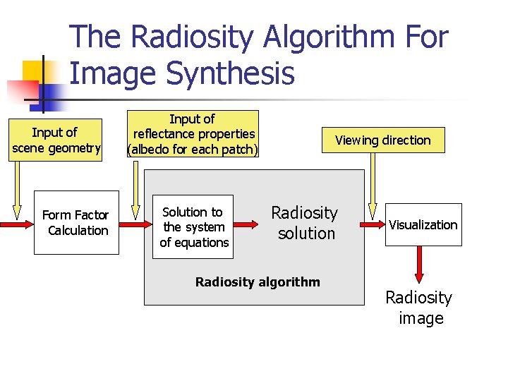
The Radiosity Algorithm For Image Synthesis Input of scene geometry Form Factor Calculation Input of reflectance properties (albedo for each patch) Solution to the system of equations Viewing direction Radiosity solution Radiosity algorithm Visualization Radiosity image
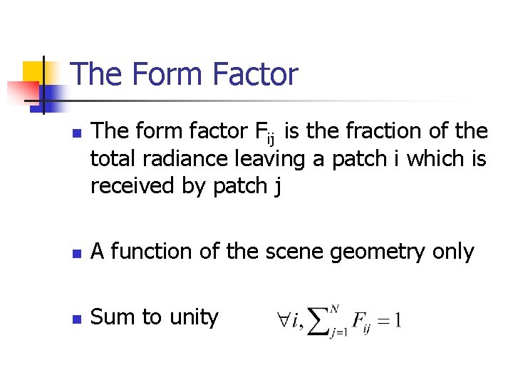
The Form Factor n The form factor Fij is the fraction of the total radiance leaving a patch i which is received by patch j n A function of the scene geometry only n Sum to unity
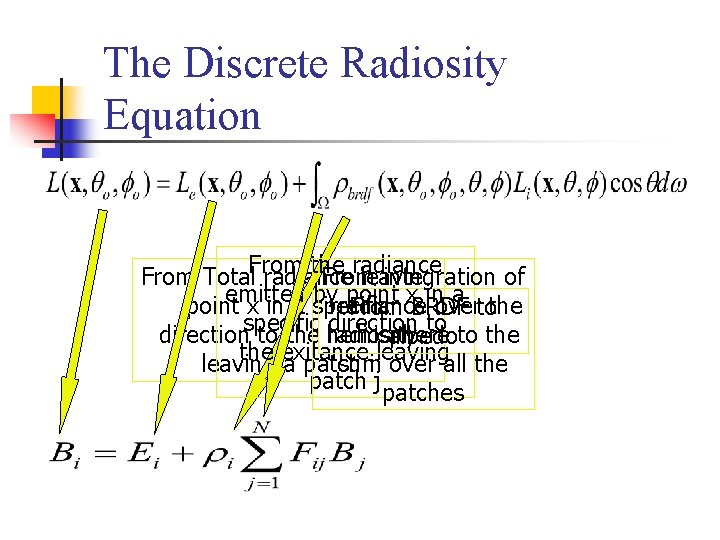
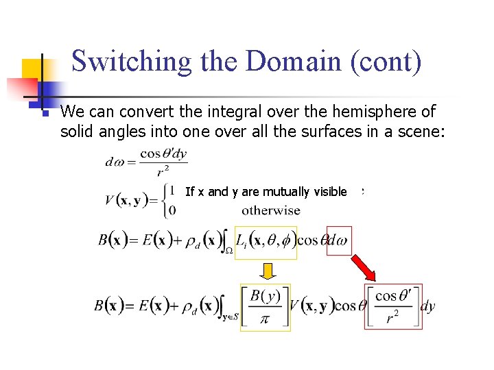
The Discrete Radiosity Equation From the radiance From Total radiance leaving From integration of emitted by point x in a specific irradiance over the From BRDF to specific direction to the radiosity hemisphere to the albedo the exitance leaving a patch i sum over all the patch j patches
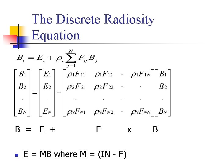
The Discrete Radiosity Equation B = E + F x B n E = MB where M = (IN - F)
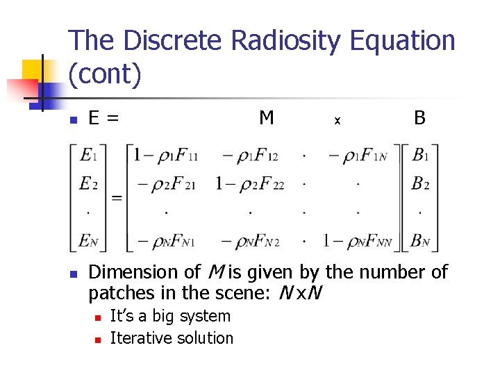
The Discrete Radiosity Equation (cont) n n E = M x B Dimension of M is given by the number of patches in the scene: N x. N n n It’s a big system Iterative solution
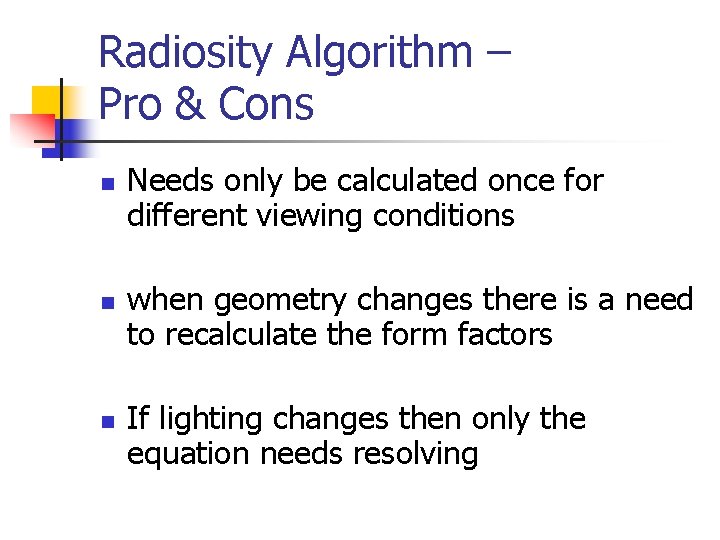
Radiosity Algorithm – Pro & Cons n n n Needs only be calculated once for different viewing conditions when geometry changes there is a need to recalculate the form factors If lighting changes then only the equation needs resolving
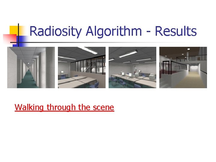
Radiosity Algorithm - Results Walking through the scene
Inverse Global Illumination Recovering Reflectance Models of Real Scenes from Photographs Yizhou Yu, Paul Debevec, Jitendra Malik & Tim Hawkins Computer Science Division University of California at Berkeley
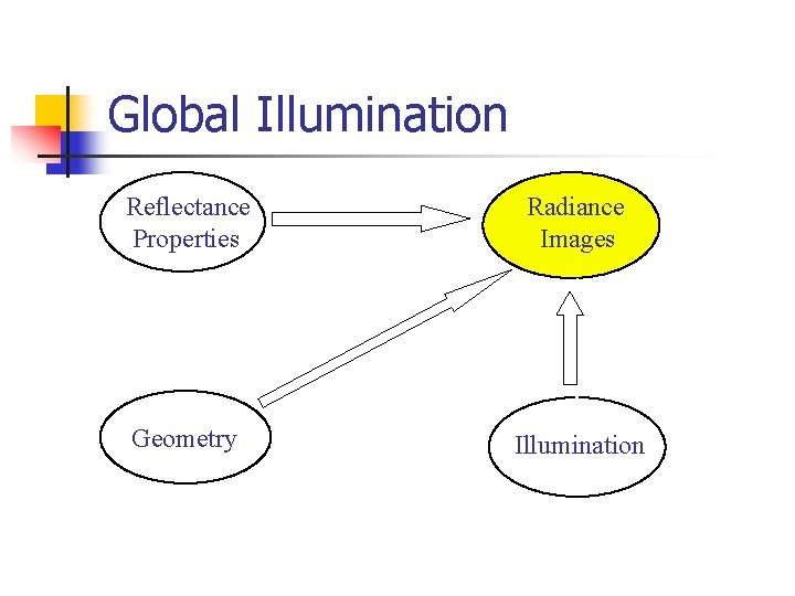
Global Illumination Reflectance Properties Radiance Images Geometry Illumination
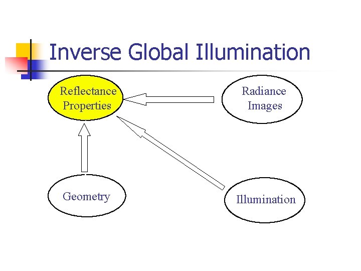
Inverse Global Illumination Reflectance Properties Radiance Images Geometry Illumination
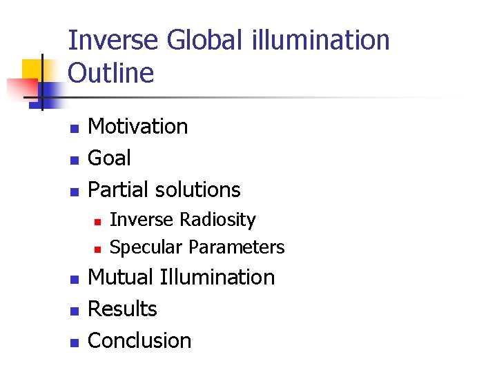
Inverse Global illumination Outline n n n Motivation Goal Partial solutions n n n Inverse Radiosity Specular Parameters Mutual Illumination Results Conclusion
Motivation n Most Image Based Rendering methods allow novel viewpoints, but not changes in lighting. This paper shows recovery of reflectance parameters of a scene. Can then relight scene.
Motivation - cont n Many authors have previously recovered reflectance parameters. e. g. , n n Specular and diffuse parameters Spatially varying BRDFs However, this is done in laboratory with controlled illumination Good for individual objects, but not for an entire scene
Goal n n n Estimation of the reflectance properties of all surfaces in the scene at once. Surfaces are illuminated in situ rather than as isolated samples. Perform all of this from a relatively sparse set of photographs.
Simplifying Assumptions n n n No transmission Known geometry Known light source positions Known cameras positions Radiance maps Specular reflectance parameters constant over large surface regions
Simplifying Assumptions - cont n n n Each surface point captured in at least one image Each light source captured in at least one image Image of highlight in each specular surface region in at least one image
First Step Toward The Full Solution n Inverse radiosity n n Pure diffuse scenes The environment is broken into patches with constant diffuse albedo
Inverse Radiosity n Input: n n Scene Geometry Lighting conditions Radiance distribution Output: n Diffuse albedo at each patch in the environment
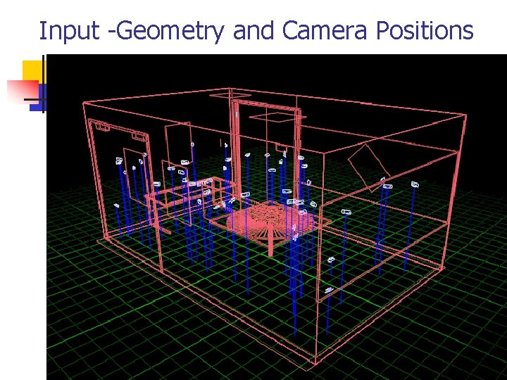
Input -Geometry and Camera Positions
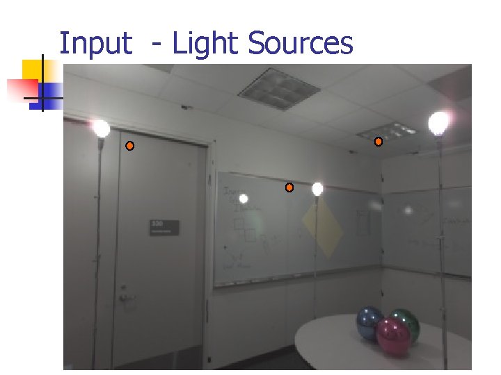
Input - Light Sources
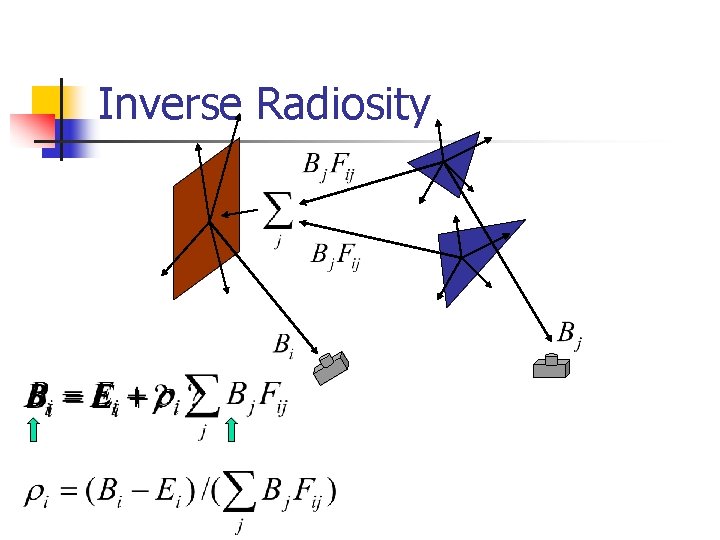
Inverse Radiosity
Second Step Toward The Full Solution n Local illumination n Single surface n Single known light source. n Uniform BRDF’s – allows both diffuse and specular reflection
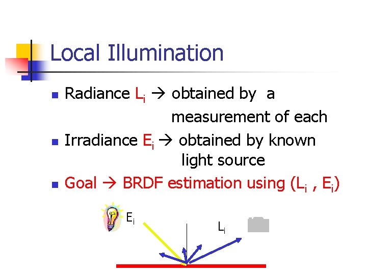
Local Illumination n Radiance Li obtained by a measurement of each Irradiance Ei obtained by known light source Goal BRDF estimation using (Li , Ei) Ei Li
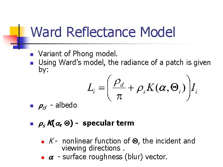
Ward Reflectance Model n Variant of Phong model. Using Ward’s model, the radiance of a patch is given by: n rd - albedo n rs K(a, Q) - specular term n n n K - nonlinear function of Q, the incident and viewing directions. a - surface roughness (blur) vector.
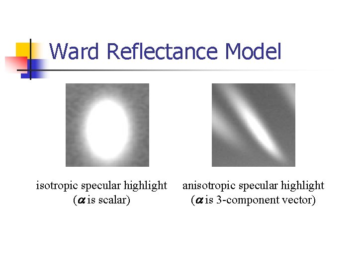
Ward Reflectance Model isotropic specular highlight (a is scalar) anisotropic specular highlight (a is 3 -component vector)
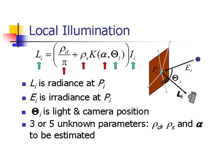
Local Illumination n n Li is radiance at Pi Ei is irradiance at Pi Qi Li Qi is light & camera position 3 or 5 unknown parameters: rd, rs and a to be estimated
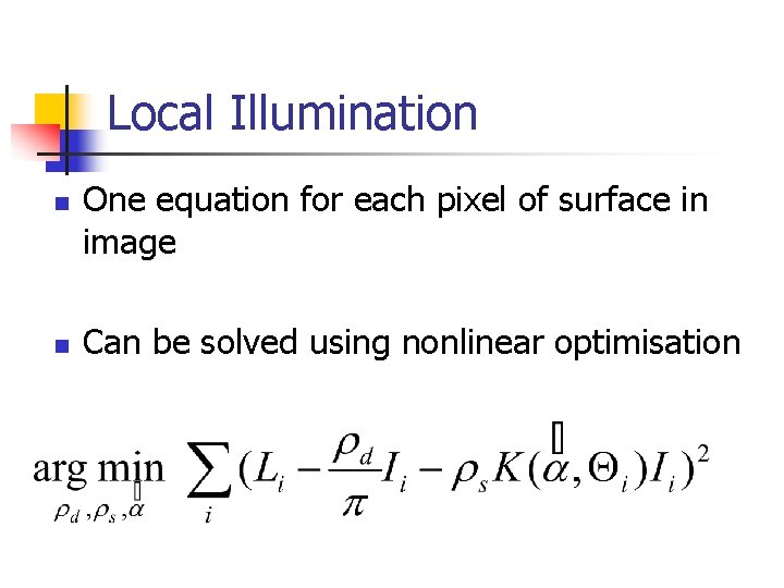
Local Illumination n n One equation for each pixel of surface in image Can be solved using nonlinear optimisation

Ready For The Real thing ….
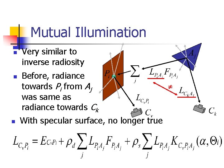
Mutual Illumination n Very similar to inverse radiosity Before, radiance towards Pi from Aj was same as radiance towards Ck With specular surface, no longer true
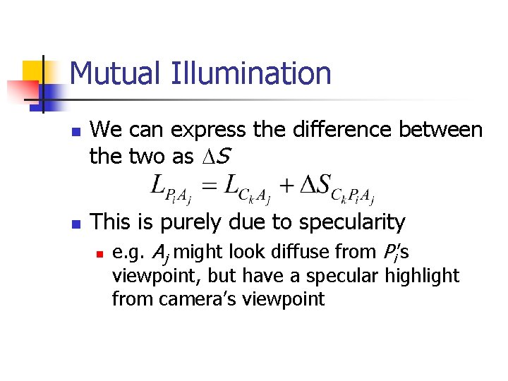
Mutual Illumination n n We can express the difference between the two as DS This is purely due to specularity n e. g. Aj might look diffuse from Pi’s viewpoint, but have a specular highlight from camera’s viewpoint
Mutual Illumination n To recover all BRDF parameters for all the surfaces we need: n n Radiance images covering the whole scene Each surface patch needs to be assigned a camera from which its radiance image is selected At least one specular highlight on each surface needs to be visible in the set of images Each sample point gives an equation
Mutual Illumination n Idea for iterative algorithm: n n assume zero DS initially do n n calculate L radiances from DS estimates using global illumination update all rd, rs, a using L radiances re-estimate DS using rd, rs, a and L loop until convergence
Mutual Illumination n n Highlight regions need special treatment: detect in advance. No guarantees for convergence. No error bound on the recovered BRDF parameter values. In practice work well.
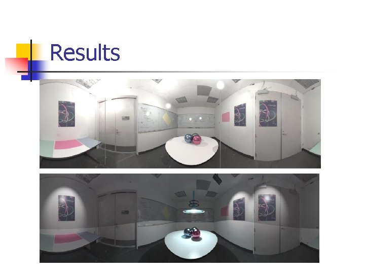
Results
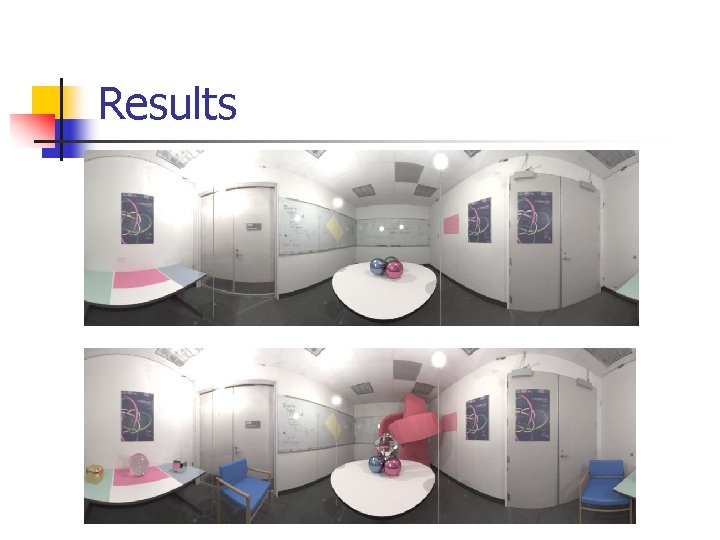
Results
Inverse Global Illumination - Summary n n Inverse radiosity Recovering specular reflectance properties from direct illumination n The reflected light was divided into diffuse and specular components Specular component was modeled using Ward’s model A new technique for determining reflectance properties of entire scenes taking into account mutual illumination.
Rendering & Reconstructing Under Complex BRDF’s - Summary n Few basic concepts n Photometric Stereo n Image Based Rendering (IBR(

The End
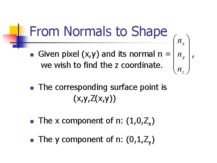
From Normals to Shape n n Given pixel (x, y) and its normal n = , we wish to find the z coordinate. The corresponding surface point is (x, y, Z(x, y)) n The x component of n: (1, 0, Zx) n The y component of n: (0, 1, Zy)
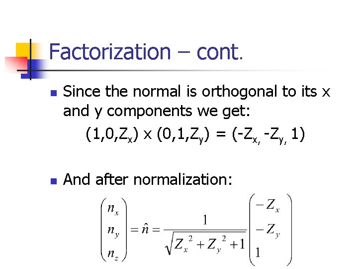
Factorization – cont. n Since the normal is orthogonal to its x and y components we get: (1, 0, Zx) x (0, 1, Zy) = (-Zx, -Zy, 1) And after normalization: n
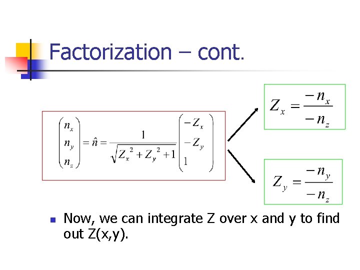
Factorization – cont. n Now, we can integrate Z over x and y to find out Z(x, y).
Radiosity & Exitance for diffuse surfaces n Diffuse surfaces, by definition, have outgoing radiance that does not depend on direction
Radiance to Radiosity n Recall: n n Simplifying the global illumination equation gives:
Switching the Domain n We still have annoying radiance terms inside the integral Radiance is constant along lines The radiance arriving is coming from a diffuse surface, y :
Switching the Domain (cont) n We can convert the integral over the hemisphere of solid angles into one over all the surfaces in a scene: If x and y are mutually visible
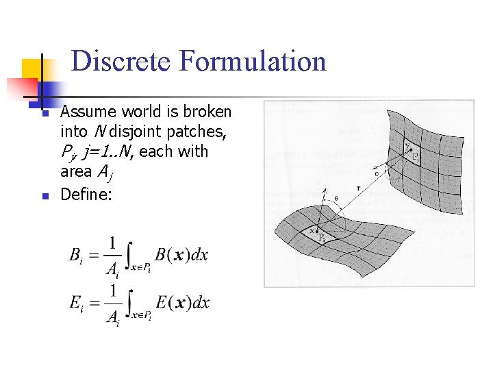
Discrete Formulation n n Assume world is broken into N disjoint patches, Pj, j=1. . N, each with area Aj Define:
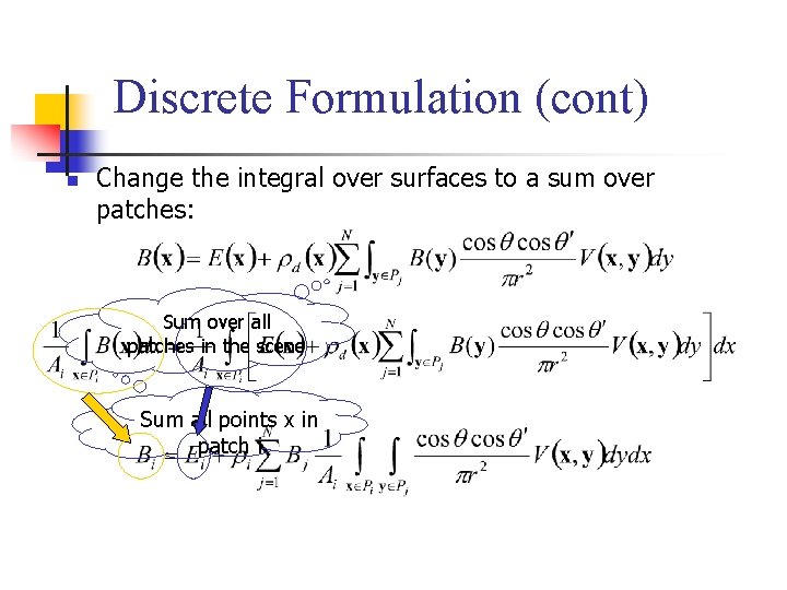
Discrete Formulation (cont) n Change the integral over surfaces to a sum over patches: Sum over all patches in the scene Sum all points x in patch i
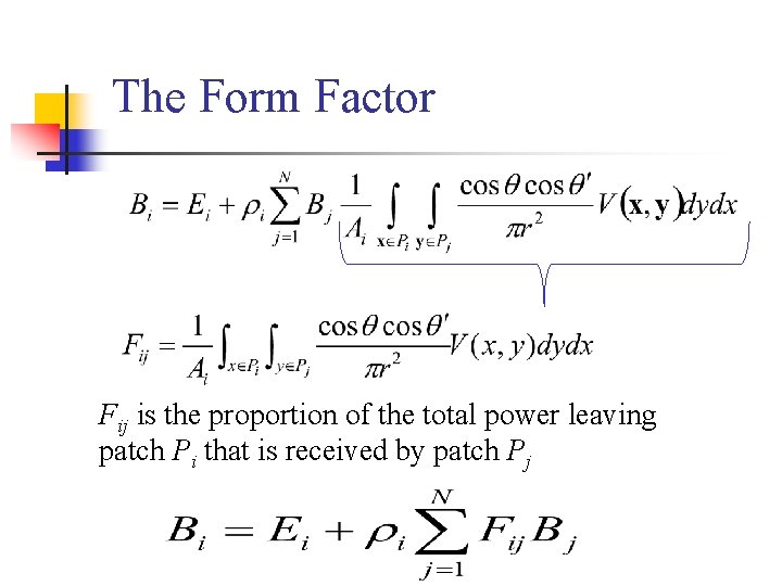
The Form Factor Fij is the proportion of the total power leaving patch Pi that is received by patch Pj
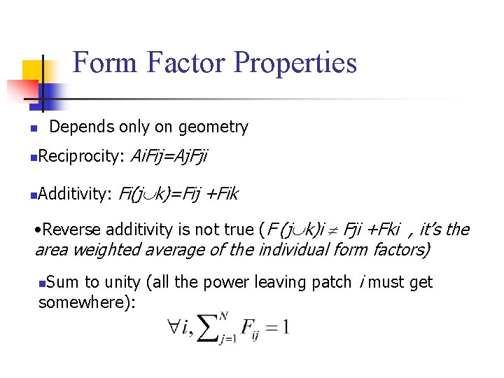
Form Factor Properties Depends only on geometry n n Reciprocity: Ai. Fij=Aj. Fji n Additivity: Fi(j k)=Fij +Fik • Reverse additivity is not true (F (j k)i Fji +Fki , it’s the area weighted average of the individual form factors) Sum to unity (all the power leaving patch i must get somewhere): n
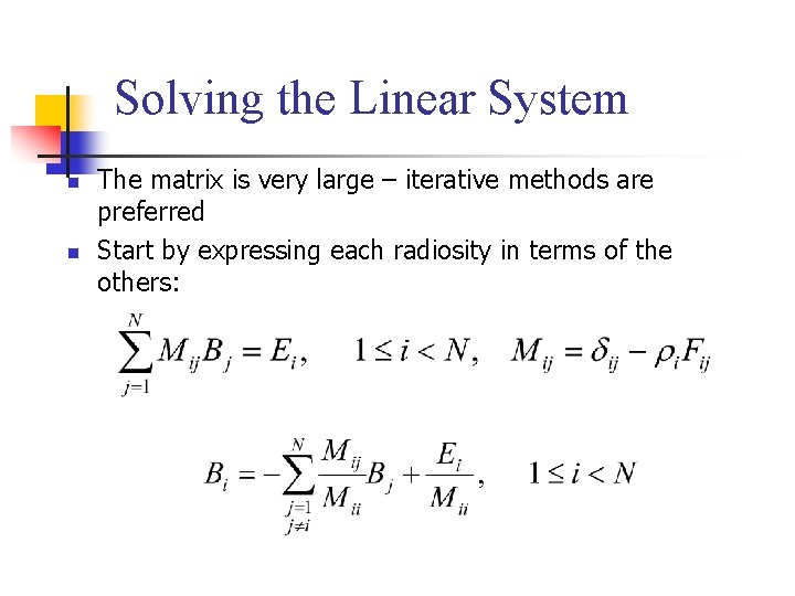
Solving the Linear System n n The matrix is very large – iterative methods are preferred Start by expressing each radiosity in terms of the others:
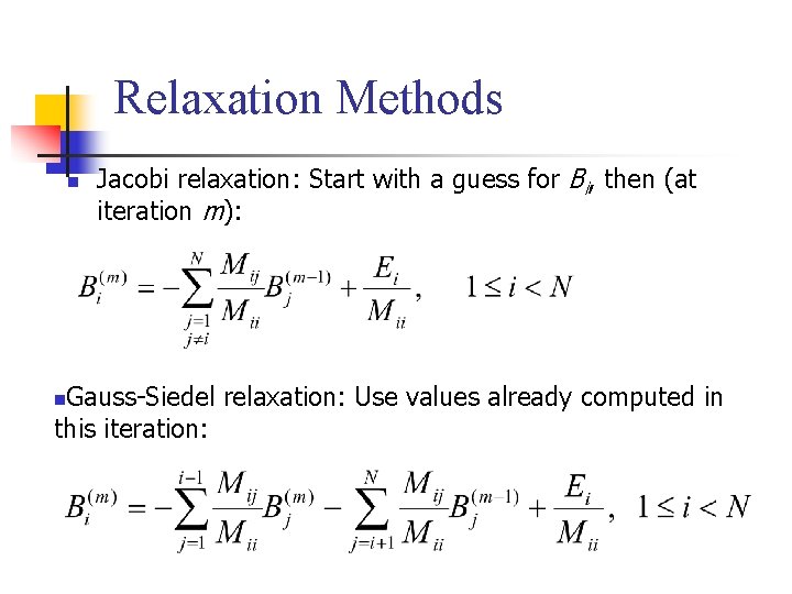
Relaxation Methods n Jacobi relaxation: Start with a guess for Bi, then (at iteration m): Gauss-Siedel relaxation: Use values already computed in this iteration: n
- Slides: 156