Reigate Grammar School ACP 34 V 1 Airmanship


 built alongside")
 Large paved areas for the servicing and turnaround of aircraft.")


 or")


- Slides: 113
Reigate Grammar School ACP 34 V 1 – Airmanship I Learning Objectives l Chapter 1 - Airfields – – – – Identify the features and facilities found on an Airfield List and compare the 3 main airfield types State how airfield runways are aligned State the significance of the two digit numbers found on the ends of runway Name the main features of a modern “Main Instrument Runway” type airfield State the main function of a RHAG and what the abbreviation stands for Identify and state the functions of the following facilities: l l l l – – Overrun Areas Arrester Barriers ORPs ASPs Taxiway Dispersals Windsocks Airfield identifying letters Explain how hazards such as specialist vehicles are identified on an airfield State the function of Approach Lighting
Airfield- an area including buildings and support installations used for the accommodation, take-off and landing of aircraft. Airport – an airfields with added facilities for freight and passengers Aircraft manoeuvring areas – parts of the airfield which have specially prepared for the movement of aircraft on the ground ( taxiways, runways, aircraft servicing platforms.
l The wind direction and length of runway are important l Present trend – one long runway or at most 2, with longer one being designated the ‘main instrument runway’ (in line with prevailing wind, lighting, radio installations and safety equipment) l 3 types or Airfields l Basic Grass Airfield l Triangular patterned runway Modern main instrument runway l
Figure 1. 1
l l Construction – concrete or layers of asphalt Dimensions – vary according to role Typical RAF airfield – 45 m wide and 1. 8 km long or more) Subsidiary runways – same width but not as long l For Transport aircraft to operate l l 60 m wide 2. 7 km long
Fig 1 -2
Markings Colour Taxiways–yellow markings Runway Numbers l The number indicates the magnetic headings of the runway direction (nearest 10 ) Examples l 238 – runway No. 24 l 058 – runway no. 06 l The magnetic heading is taken from the direction of approach. Therefore the heading for one end of the runway is 180 different from the other
Fig 1 -2
Markings Threshold Markings l Centre-Line and Side-Stripe markings Runway threshold- longitudinal white lines painted symmetrically about the runway centre-line l l l Indicated as a broken white line (arrowheads in the sterile area) Chevrons and a bar are added when threshold is moved up runway because of obstruction. Therefore aircraft are at safe height when it l Side-stripe markings are added crosses obstruction Beginning of runway before threshold markings is known as the ‘sterile area’ to runways which have little contrast between the runway and the surrounding area
l l l Arrester Gear Brings aircraft to a stop in a short distance Aircraft needs a hook to engage cables RAF use RHAG – Rotary Hydraulic Arrester Gear – large paddles rotating in liquid Over-Run Areas and Arrester Barriers l Where space permits l Over-run areas, clear of obstacles and with a reasonably even surface l Can also have barriers consisting of large strong nets made of nylon rope which can be raised and lowered
Operational Readiness Platforms l Specially prepared areas (for fighters and strike aircraft) built alongside the end of a runway l Used for parking aircraft for rapid take-off (‘scramble’)or final flight preparation Dispersal Hardstandings l The aim is to spread the aircraft around the airfield, to make it more difficult for enemy aircraft to damage or destroy all the parked aircraft during an attack
Aircraft Servicing Platforms (ASPs) Large paved areas for the servicing and turnaround of aircraft. Taxiways Connect all the various parts of the aircraft manoeuvring area and enable aircraft to move about easily (minimum of 15 m wide)
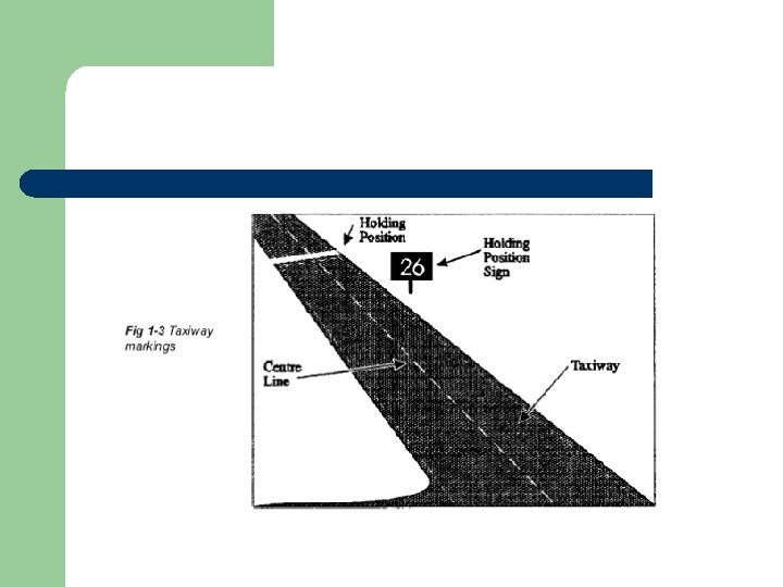
Taxiway markings l Centre line- broken yellow line l Edge marking – dashed yellow line - where there is little contrast between the taxiway and the surrounding area l Holding position- At a junction of a taxiway with a runway, taxiing aircraft are required to ‘hold’ until it is safe to move onto the runway. Indicated by two yellow lines, one solid and one broken. It is painted at right angles to the taxiways centre line and 70 m from the nearest edge of the runway. The holding position sign displays the runway number in black on a yellow background (old) or white on a red background (new)
l l l Windsock Normally there are two or more windsocks on an airfield to provide a quick and easy way of indicating wind direction Positioned away from trees and buildings which may cause local wind turbulence The principle windsock has a white ring round its base l l l Obstructions May be permanent (building) or temporary (mechanical digger) Clearly marked by day and night Vehicles may be painted with red and white squares and have yellow roofs or be equipped with a flashing amber or blue lights
l l l Airfield Identification Each airfield is identified by means of two letters. (i. e SY for Shawsbury) Displayed in a ‘signal square’ close to the ATC tower Identification beacons flash the same letters in Morse Code l l Airfield lighting Lights are designed to assist pilots to taxi aircraft safely and to take-off and land on the runway in use Many of the lights will be hooded so that they can only be seen from a certain angle.
l The main types of lighting are: l Airfield Identification Beacon- flashed the airfield identification letters in Morse code using a high intensity red light. l Obstruction Lights – All high buildings, towers, hangers, both on and in the vicinity of the airfield, are marked by red obstruction lights l Flood lighting- ASPs are often lit by powerful flood lights set on pylons l Holding position – these signs are illuminated at night by their own internal lighting l Taxiway Lights – less than 18 m wide, marked by blue edge lights along each side- 18 m or more are marked only along the centre line and the lights are green
Approach Lighting
l Approach lighting- installed outside the airfield boundary and often set on poles, to form a special pattern (see picture) This pattern helps the pilot judge the aircraft’s height and to line up with the runway on the approach to land. In poor visibility or a night it helps the pilot to find the approach path visually towards the end of a radio or radarcontrolled approach. l Threshold lights- marked by a row of green lights across the runway at the touchdown end. Plus ‘wings’ of three green lights on each side of the runway. ‘wings’ are omitted if the threshold is displaced up the runway. l Runway lights- Main runway have high-intensity unidirectional edge lights. Plus come omnidirectional edge lights to help pilots in the circuit judge their position.
l Sample questions
Answers
l l l Chapter 2 – The Tutor 2. 1 Name the units which operate the Grob Tutor aircraft for Air Cadet 2. 2 Describe the Tutor’s basic configuration 2. 3 Describe the materials covering the surfaces 2. 4 Name the engine and the type and amount of the fuel used in the Tutor 2. 5 Explain the starting method used with this engine 2. 6 Explain the need for entering the aircraft using the walking strips 2. 7 Name the 6 basic aircraft instruments 2. 8 Identify and explain the function of the aircraft primary flying controls 2. 9 Name the 3 basic engine instruments 2. 10 Identify and explain the function of the engine controls
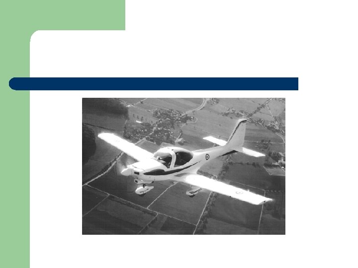
l l We fly at 6 AEF – air experience flight at RAF Benson AEFs are equipped with GROB Tutor aircraft They are single engined, low winged monoplanes. They hold 33 gallons of aviation gasoline in two tanks in the wings (2 ½ flying hours) (some fast jets use this amount of fuel taxiing to the end of the runway) l They are equipped with a 180 hp Lycoming engine and can fly at a maximum of 185 kts
Other features l l l Steerable nose wheel – brakes are on the two main wheels Side-by side seating with dual controlspilot/cadet can have full control – cadets are in the left seat Body made of carbon reinforced plastic- must walk of the marked ‘walking strip’ provided (on wing)
Other features l l 2 radios - air- to - ground - air- to - air One UHF and one VHF band DO NOT INTERFERE WITH ANY SETTINGS TOUCH NOTHING IN THE COCKPIT
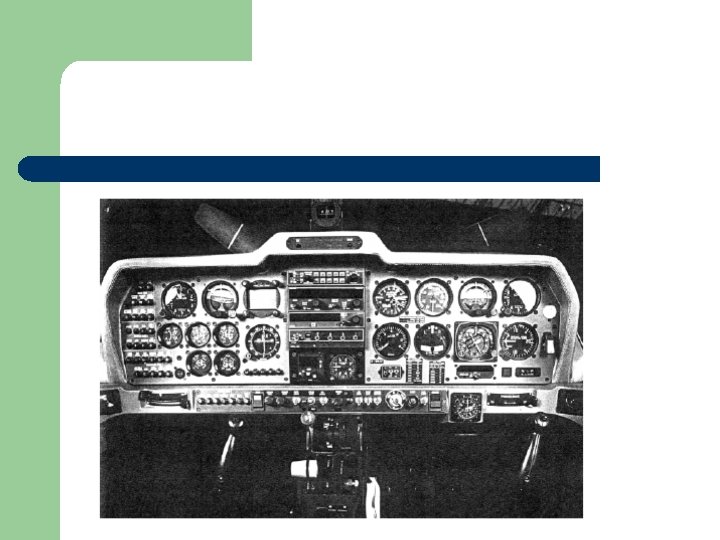
Atitude indicator Horizontal Situation Indicator Airspeed Indicator 6 Instruments Turn & Slip Indicator Rate of Climb & Descent Indicator Altimeter
‘Instruments’ – indicate what the aircraft is doing Atitude Indicator -Nose up/ down -Banked left/right Airspeed Indicator -Calibrated in knots Altimeter -Aircrafts height above preset datum -3 hands – one hundreds, one thousands, one 10 thousands -Read carefully Rate of Climb & Descent Indicator -Vertical Speed Indicator -Rate of Climbing or descending Turn & Slip Indicator -Rate at which aircraft is turning -The direction of turn- if skidding or slipping Horizontal Situation Indicator Synchronised with compass Tells heading
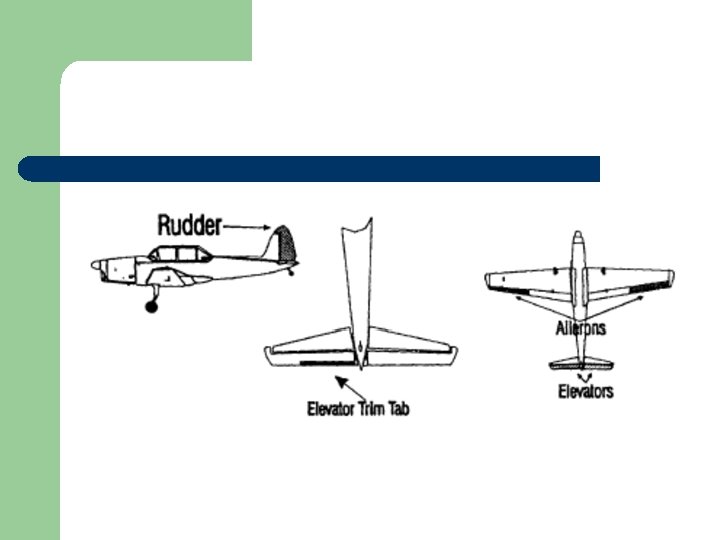
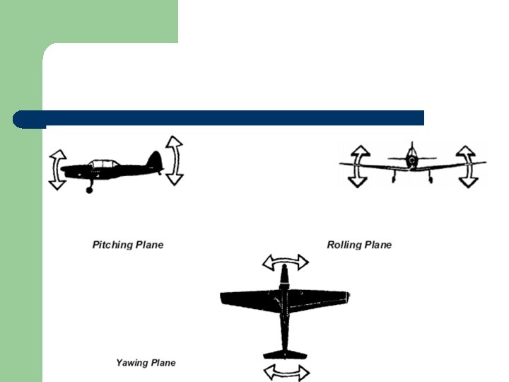
Control Column ‘Stick‘ Ailerons Control Column ‘Stick’ Elevators 3 Controls Rudder Redals
‘Controls’ – used to manoeuvre the aircraft Control Column ‘stick’ Ailerons on wings ‘Rolling Plane’ -Move left (port) and right (starboard) Control Column ‘stick’ Elevators Elevator on tail ‘Pitching Plane’ -Move up and down Rudder Pedals -at pilot’s feet -causes aircraft to ‘Yaw’ -Used to turn without banking -Used during aerobatics or to maintain balanced flight
RPM Engine Instruments Temperature & Pressures Manifold Pressure
Engine Instruments RPM Revolutions per second 20 gives 2, 000 rpm Manifold Pressure How much power is being supplied by the engine (responds to throttle movements) Temperature and Pressures Of engine
Throttle Engine Controls Mixture Control RPM control
Engine Controls Throttle Pushed forward increases engine output RPM Control Blue lever to right of throttle - rpm of engine - efficiency of propeller Mixture Control Red lever next to RPM -fuel/air ratio
Wheel Brakes Other Controls Elevator Trimmer Flaps
Other Controls Wheel Brakes Left of right to control steering on ground while taxiing in confined areas -both used to brake Flaps Used on approach to landing -To lower approach speed (safety) -- To lower nose attitude- better vision -Located on rear inner edge of each wing Elevator Trimmer To make fine adjustments to elevator so that aircraft can be flown at selected pitch attitude with pressure on the stick
Sample Questions
Answers
l l l l Chapter 3 – Pre-flight briefing – Air Experience Flying in Tutors 3. 1 Understand the purpose and importance of the pre-flight briefing 3. 2 Understand the importance of awareness and lookout on the airfield 3. 3 State the initial aim of Air Experience Flying (AEF) 3. 4 Describe how to fit adjust and release the parachute 3. 5 Describe the Life Preserver and its contents 3. 6 Describe how to operate the Aircraft safety harness 3. 7 State the actions to be taken in an emergency 3. 8 State the actions to be taken when the order “JUMP” is given 3. 9 Understand the importance of checking foreign object 3. 10 State when a cadet is permitted to touch/operate any controls or equipment in the aircraft 3. 11 Understand the dangers associated with aircraft propellers 3. 12 State the actions to be taken if a cadet has any cold or flu like symptoms
Pre-flight Briefing l l l A successful flight is dependent on preparation by the captain and crew before take-off. They must understand the objective of the flight in order to make it safe and efficient. A Nimrod brief many take many hours, whereas a short flight in a simple aircraft in a local area, would only require a short brief.
Your Responsibility l l l To learn about Airfields and Instruments/Controls in the Tutor To listen carefully to the film before your flight Stay in party and keep a look out.
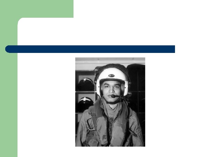
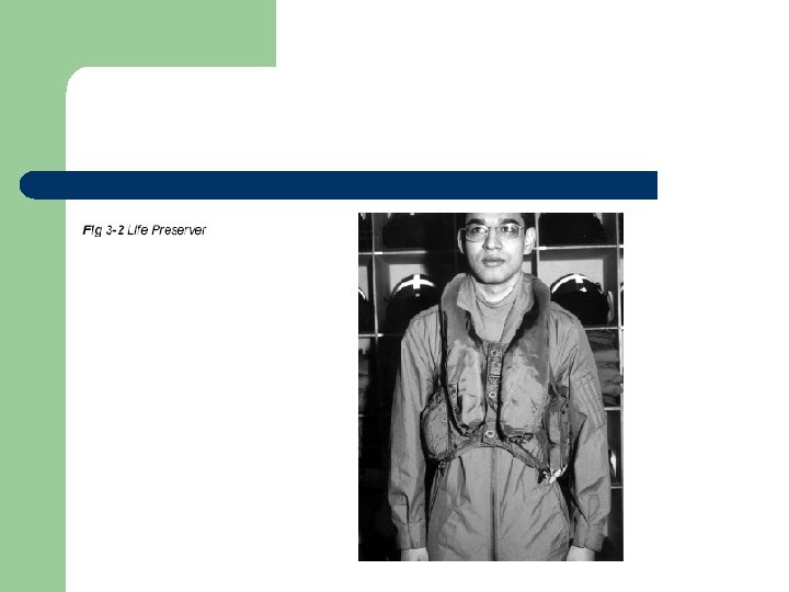
Your Briefing at AEF l l l The aim of the exercise Fitting and operation of parachutes Fitting and operation of protective helmet Fitting and operation of aircraft safety harness Checking for loose articles Action to be taken in an emergency – abandoning aircraft Can/Cannot touch in Aircraft Basic Operation of aircraft radio The local flying area Weather conditions Precaution of the ground in aircraft manoeuvring area Medical aspects of flying
Aim of the exercise l l Initially - to introduce you to the aircraft and familiarise you with the cockpit environment Effect of some of the aircraft controls May have a chance to fly the aircraft As experience is gained – other aspects will be introduced, such as turning and aerobatics
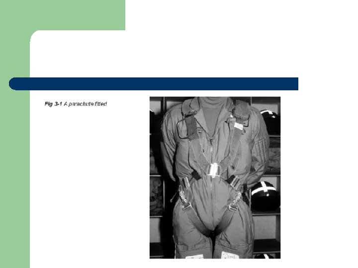
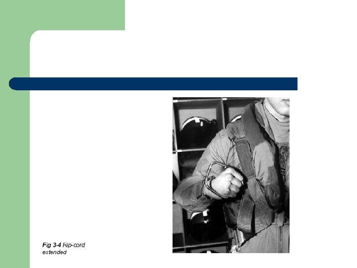
Parachute l l Back type – parachute, 2 leg straps, chest strap connecting the shoulder straps and rip chord and handle Fitting l l Connect chest strap first Leg straps individually- between legs and clip fasteners to rings situated at waist level outside hip joints
l l Adjustment – lengthen and shortening 4 adjuster straps. Method of release – Quick release l l l Release chest strap first Slide metal cover sideways using the thumb catches to unlock the two halves Then release leg straps
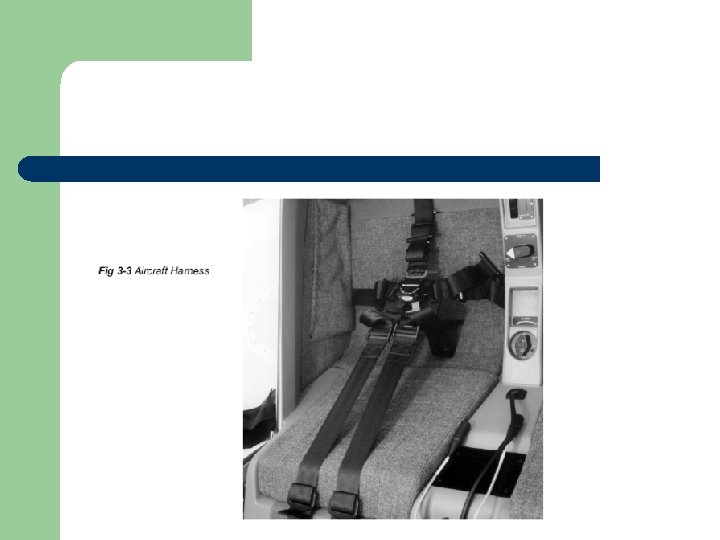
Aircraft Safety Harness l l Attached to air craft It is to ensure that you stay in seat of aircraft when inverted, plus it provides crash protection! 5 adjustable straps – 2 shoulder, 2 lap and 1 from centre of seat with quick release box at free end. Fitting – loosen adjustable flap straps and insert 4 adjustable harness lugs
Aircraft Safety Harness l Adjustment – l l Pull on free ends of lap strap tightly at possible Pull down shoulder straps Finally the 5 th strap is tightened – negative G strap Method of release – depress yellow thumb catch then turn knob 60 left or right
Loose Article Check l l l Loose articles – if dropped in cockpit could lead to dangerous situation if not recovered Numerous accidents are blamed on foreign objects left by careless people They foul flying controls and cause serious accidents Remove all objects from pockets before If you drop something report it!
Action in an Emergency l l l DO NOT PANIC DO AS YOU ARE TOLD You must know what to do if the decision is made to abandon the aircraft – – – They will give the warning order ‘Check Parachutes’ They will jettison the canopy- if not pull back handle- push release – canopy may need to be pushed off with hands They will give the order ‘JUMP’
l l l On given the order to ‘JUMP LUMP’ Release the Aircraft Safety Harness Not your parachute!– Turn it 90 degrees either way Stand up in the cockpit and dive head first over the trailing edge of the wing When clear of the aircraft pull the metal ‘D Ring’ attached to the rip cord – (it comes out a long so be sure to pull it to its fullest extent) Bend your legs and roll on landing
Precautions on the ground l l l Keep alert with your eyes and ears open when walking about Beware of propeller discs Keep a good look out for moving aircraft at all times and move only where you are told you may go
Medical Aspects l l l As altitude increases the air pressure reduces The human body normally adjusts without difficulty However, with a cold, discomfort may well be experienced in the ears and sinuses Blocked tubes can prevent pressures form equalising or your ears form clearing, sometimes with painful results RAF aircrew do not fly in these circumstances and you must not do so either
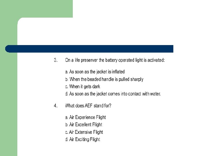
Sample Questions
Answers
l l l l Chapter 4 – VGS and Gliding 4. 1 State the medical and physical requirements before being allowed to glide 4. 2 State the age requirements for solo cadet flying 4. 3 Describe how team work is fundamental to cadet gliding 4. 4 State the location of gliders airbrakes and explain their function 4. 5 Name the instruments in a glider cockpit 4. 6 State the glider launch orders and explain their meaning 4. 7 Describe in simple terms soaring flight
l l l We glide at 615 VGS in Kenley It provides glider training for cadets The Viking glider has tandem seating for the crew with dual controls, the instructor occupying the rear seat
l Physical limitations – – Minimum weight for gliding is 48 kg Maximum weight for gliding is 103 kg
l l l You begin to gliding with a gliding induction course (GIC) or air experience gliding (AEG) Opportunities for pilot training will follow on the gliding scholarship (GS) course, and cadets who show an aptitude for gliding are able to fly solo at or above the age of 16 years After flying solo there are opportunities to carry out your advanced gliding training (AGT) and some may eventually become Flight Staff Cadets and gliding instructors
l l When you go gliding at 615 VGS, individuals are given clearly defined duties, which they must carry out responsibly! This is so that gliders can be launched safely and, after landing, brought back to the launch point.
l l Glider’s controls and control surfaces are like those of a conventional aircraft. In addition, winch gliders have – – A yellow toggle which the pilot pulls to release the cable when the glider has reached the top of the launch A lever to operate the air brakes
l l Air Brakes When extended they increase the drag and reduce the lift, allowing the glider to descend more quickly without increasing the speed. This allows the pilot to land in a much smaller space than would otherwise be possible
l l Seat Harness A five point harness fitted to each seat Occupants can strap themselves securely to the seat
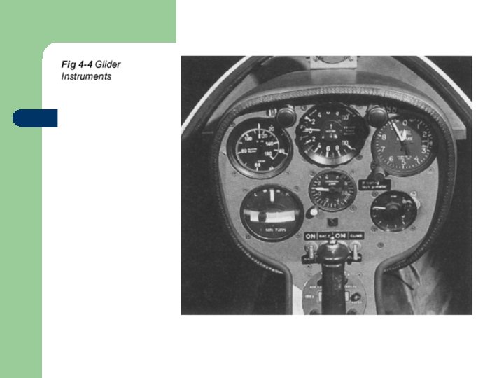
Flight Instruments l l A glider is normally flown by visual reference to the horizon However, four flight instruments are fitted for accuracy 1. Airspeed indicator 2. Altimeter 3. Turn and slip indicator l l l 4. Variometer Specific to gliders Purpose is to indicate whether the glider is losing or gaining height. It is invaluable in helping the pilot find rising air, and to stay in it to prolong the flight
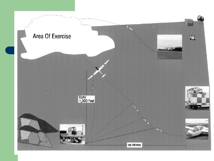
Launching l l l A glider has no engine and must be accelerated to its flying speed some other way The most common method is the winch launch Rarely aero-towing is used l l The winch A drum on which is wound about 1500 m of strong flexible steel cable The drum is turned by a powerful engine which the winch driver controls through an automatic gearbox
‘ALL OUT’ for Take Off l l l Winch is located close to the upwind boundary of the airfield Cable is attached to the rear of a motor vehicle and drawn out to the launch point When the pilot is ready the cable it attached to the glider The pilot checks there is no hazard from behind, by asking the wing tip holders (YOU!) ‘ALL CLEAR ABOVE AND BEHIND’ Then Calls ‘TAKE UP SLACK’
l l l l The winch driver is signalled using either lamp signals or radio On receiving the signal the winch driver slowly reels in the cable until it is taut When the pilot is ready he will order ‘ALL OUT’ The signaller signals the winch driver who opens the winch throttle to wind the cable in The cable pulls the glider forward and after a short distance it become airborne Initially the glider climbs gently, but the attitude quickly steepens When the cable is about 70 to the horizontal, the pilot releases it and is then free to commence the gliding exercise
l Winch driver
l l When released the cable falls to earth, steadied by a small parachute It is then reeled in by the winch driver for the next launch The height gained by the glider depends on wind speed, speed at which the cable is being wound and the length of the cable being used A rough estimate - 1, 000 m cable gives a 1, 000 m launch height and a launch last 4 to 10 minutes.
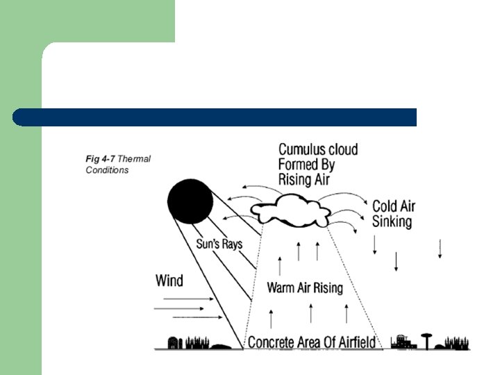
Soaring and Thermals l l l Soaring is the art of finding rising air and , then using it to gain height, thus prolonging the flight. Thermals are caused by uneven heating of the earth on hot, sunny days. Green fields, woods and lakes do not heat up rapidly Concrete or tarmac areas will become much hotter than the surrounding green fields The air over the concrete will therefore rise (like a hot air balloon); this rising air is called a Thermal
l l Thermals are not continuous- the warm air being released in the form of bubbles which rise at intervals like invisible air balloons A cumulus clouds give pilots a good idea of where thermals are forming. If thermal activity is suspected the pilot will keep an eye on the variometer and when he finds rising air the pilot will try to circle in it and gain height This requires considerable skill and experience to get maximum use of thermals
l l Rising air can also be found on the windward side of hills When the surface wind strikes the face of a hill or ridge it will be deflected upwards, becoming an up-current
Sample Questions
Answers
l l l Chapter 5 – Gliding – Vigilant 5. 1 Describe the characteristics of self launching gliders 5. 2 State the engine used to power 5. 3 State the type of fuel used and the tank capacity 5. 4 State what the abbreviation SSR stands for 5. 5 Identify the airbrakes, and the cockpit controls used to operate them 5. 6 Explain the need of pre-use checks 5. 7 Explain the need for using Flight Reference Cards (FRCs) 5. 8 State the need to carry out a prop check prior to engine start 5. 9 State the checks carried out during taxiing 5. 10 State the height at which exercises begins
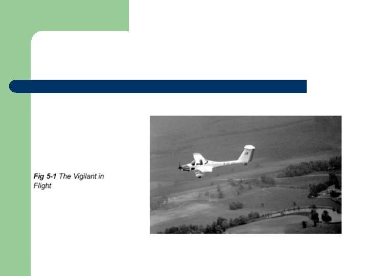
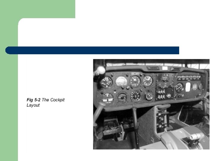
l l l The vigilant differs from other gliders in that it has an engine and propeller so that it can be launched itself. It can be flown by allowing the engine to idle or by shutting down the engine. It is used to train cadets in the effect of controls, climbing, gliding, turning, stalling, circuit flying, approach and landing. The glider will soar with reasonable soaring conditions. The engine is not powerful enough for rapid climbing. (5 min to reach 2, 000 ft) Reduced ground handling time means more airborne time.
l l l Engine – GROB 2500 E 1 Direct drive to a 2 bladed variable pitch propeller with 3 settings A 100 -litre (22 gallon) fuel tank is mounted in the fuselage behind the pilot’s seat.
Radio
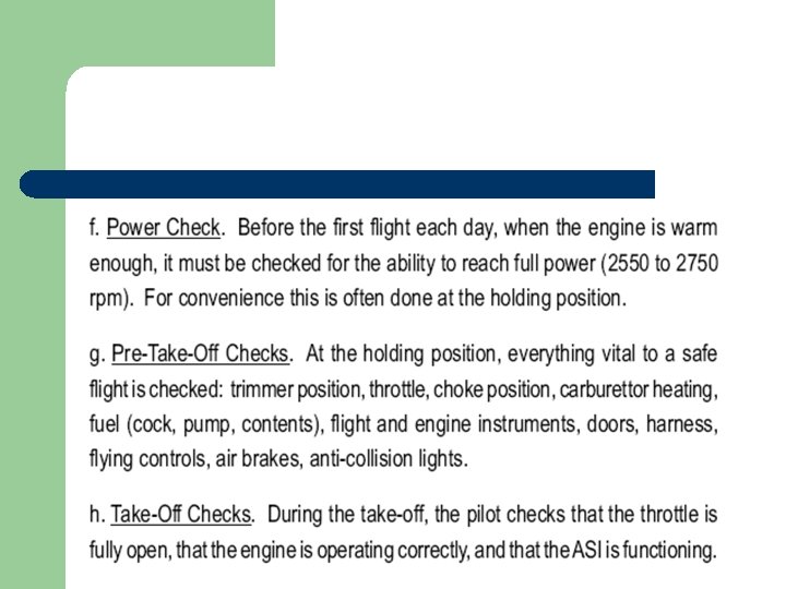
Checks
l Fig 4. 4
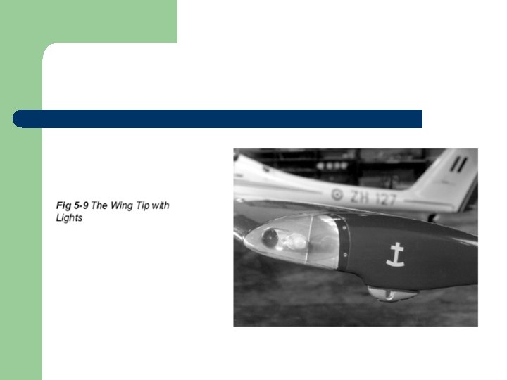
l Fig 4 -7
Area of exercise picture
Answers