
Registers State Machines Analysis Section 7 1 Section
- Slides: 16
Registers; State Machines Analysis Section 7 -1 Section 5 -4
Definition • Register – a set of flip-flops ♦May include extensive logic to control state transition ♦register also refers to fast memory for storing data in a computer 2
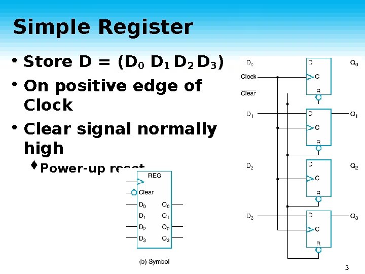
Simple Register • Store D = (D 0 D 1 D 2 D 3) • On positive edge of Clock • Clear signal normally high ♦Power-up reset 3
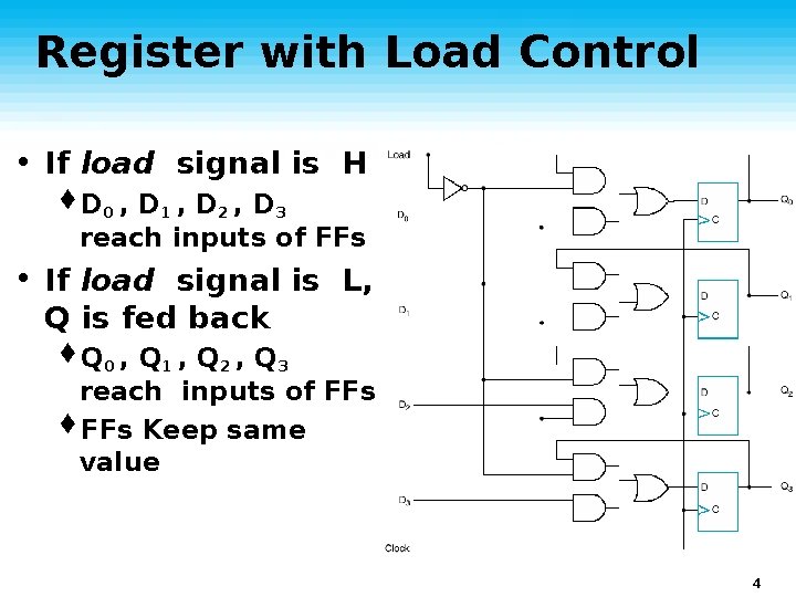
Register with Load Control • If load signal is H ♦D 0 , D 1 , D 2 , D 3 reach inputs of FFs • If load signal is L, Q is fed back ♦Q 0 , Q 1 , Q 2 , Q 3 reach inputs of FFs ♦FFs Keep same value 4
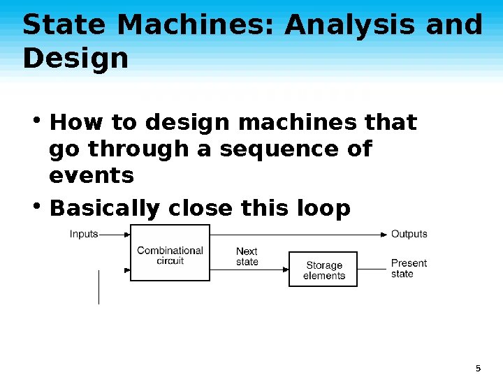
State Machines: Analysis and Design • How to design machines that go through a sequence of events • Basically close this loop 5
Analysis of Sequential Circuits • Earlier we learned how to analyze combinational circuits • Now extend to synchronous sequential ♦Include time • We’ll use state tables and state diagrams 6
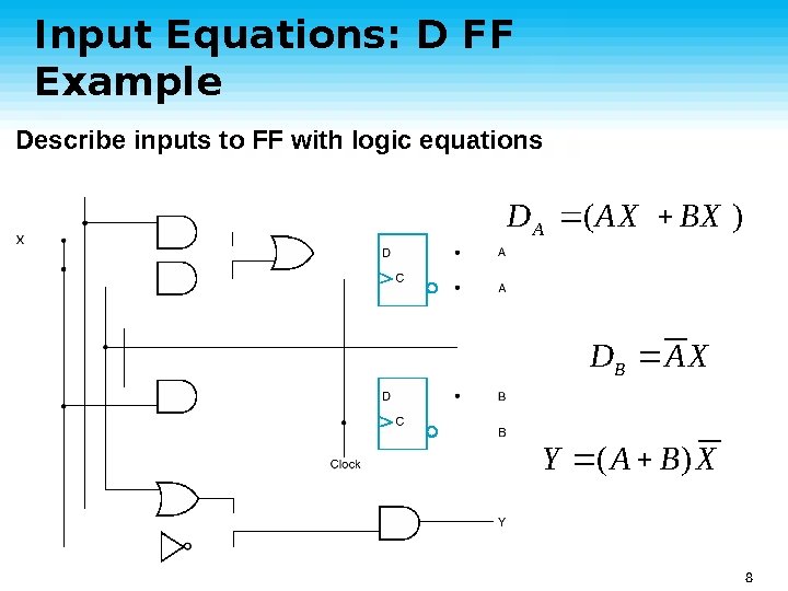
Input Equations: D FF Example Describe inputs to FF with logic equations D A (AX BX ) DB A X Y ( A B) X 8
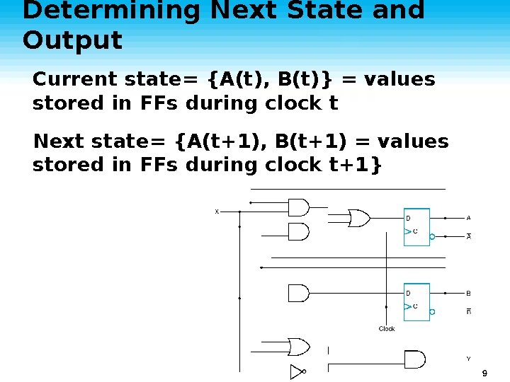
Determining Next State and Output Current state= {A(t), B(t)} = values stored in FFs during clock t Next state= {A(t+1), B(t+1) = values stored in FFs during clock t+1} 9
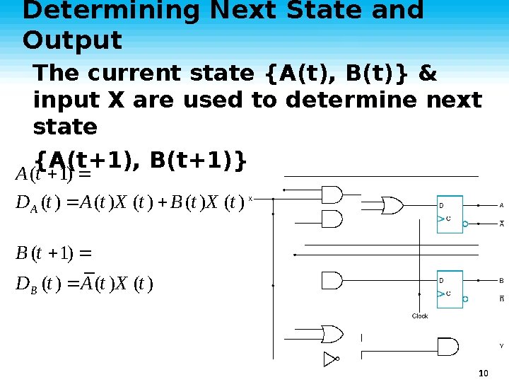
Determining Next State and Output The current state {A(t), B(t)} & input X are used to determine next state {A(t+1), B(t+1)} A (t 1) D A (t )X (t ) B (t )X (t ) B (t 1) D B (t ) A (t )X (t ) 10
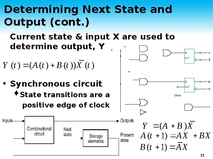
Determining Next State and Output (cont. ) Current state & input X are used to determine output, Y Y (t ) (A (t ) B (t ))X (t ) • Synchronous circuit ♦State transitions are at positive edge of clock Y (A B )X A (t 1) AX BX B (t 1) AX 11
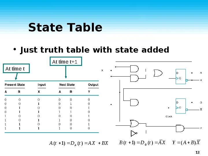
State Table • Just truth table with state added At time t+1 At time t A (t 1) D A (t ) AX BX B (t 1) D B (t ) AX Y ( A B ) X 12
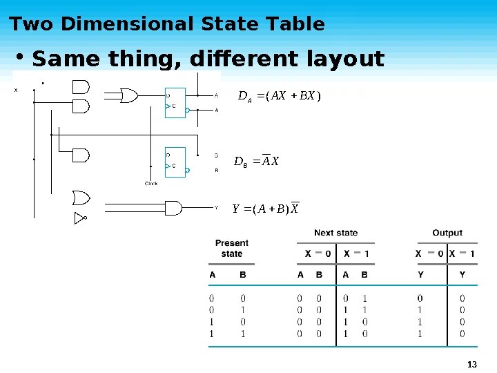
Two Dimensional State Table • Same thing, different layout DA ( AX BX ) DB A X Y ( A B) X 13
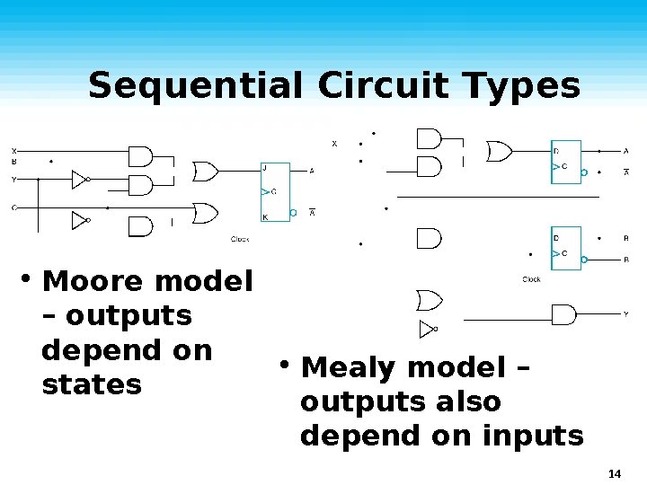
Sequential Circuit Types • Moore model – outputs depend on • Mealy model – states outputs also depend on inputs 14
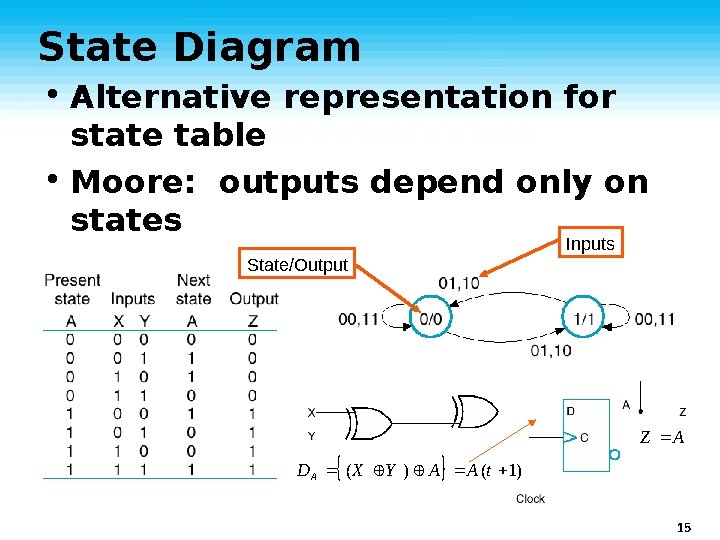
State Diagram • Alternative representation for state table • Moore: outputs depend only on states Inputs State/Output Z A D A (X Y ) A A (t 1) 15
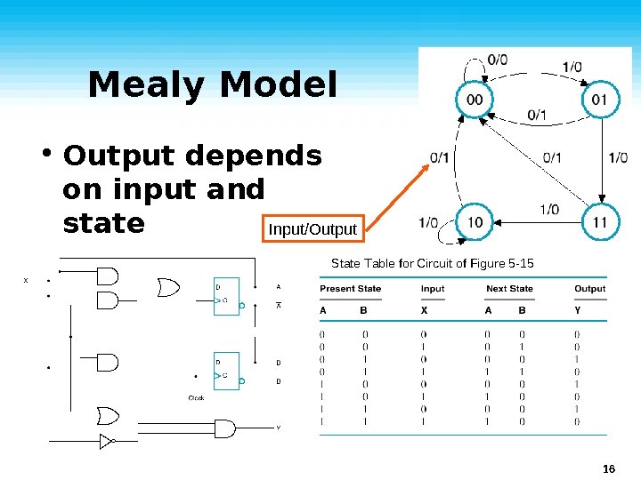
Mealy Model • Output depends on input and state Input/Output ----------------------State Table for Circuit of Figure 5 -15 State Table for Circuit of Figure 6 -17 16
State Table vs. Diagram • Same information • Table is perhaps easier to fill in from description • Diagram is easier for understanding and writing code ♦You can label states with English description 17