Rectifiers Diodes and Diodes Circuits Rectifier Circuits One


 equals the peak value of the input voltage, The")


 is an indication of the effectiveness of the")
- Slides: 23
Rectifiers
Diodes and Diodes Circuits Rectifier Circuits One of the most important applications of diodes is in the design of rectifier circuits. Used to convert an AC signal into a DC voltage used by most electronics. The Basic DC Power Supply
The Basic DC Power Supply • Transformers changes ac voltages based on the turns ratio between the primary and secondary. • The rectifier converts the ac input voltage to a pulsating dc voltage. • The filter eliminates the fluctuations in the rectified voltage and produces a relatively smooth dc voltage. • The regulator is a circuit that maintains a constant dc voltage for variations in the input line voltage or in the load.
Half wave rectifier operation
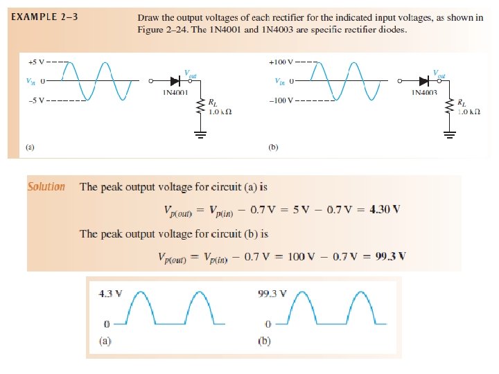
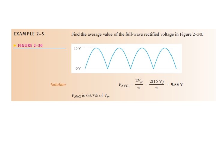
Average Value of the Half-Wave Output Voltage The average value of the half-wave rectified output voltage is the value you would measure on a dc voltmeter. Mathematically, it is determined by finding the area under the curve over a full cycle, Effect of the Barrier Potential on the Half-Wave Rectifier Output The effect of the barrier potential on the half-wave rectified output voltage is to reduce the peak value of the input by about 0. 7 V.
The peak inverse voltage (PIV) equals the peak value of the input voltage, The PIV occurs at the peak of each half-cycle of the input voltage when the diode is reverse-biased. In this circuit, the PIV occurs at the peak of each negative half-cycle.
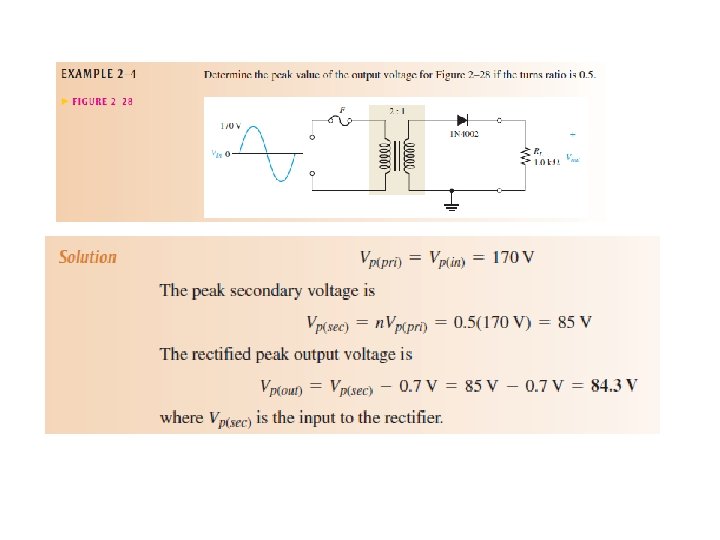
Transformer Coupling The secondary voltage of a transformer equals the turns ratio, n, times the primary voltage. n is “the number of turns in the secondary (Nsec) divided by the number of turns in the primary (Npri). The peak secondary voltage, Vp(sec), in a transformer-coupled half-wave rectifier is written in terms of Vp(sec) as
Full wave rectifiers
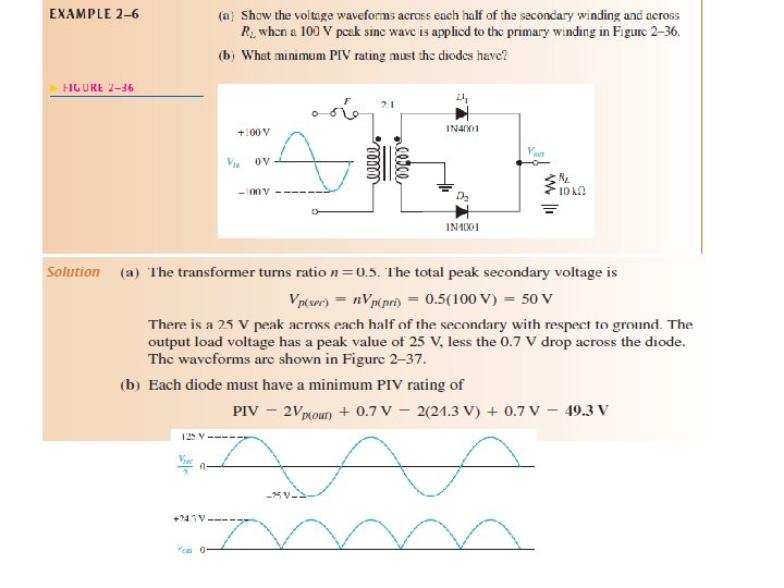
Center-Tapped Full-Wave Rectifier Operation
Center-Tapped Full-Wave Rectifier Operation
Effect of the Turns Ratio on the Output Voltage
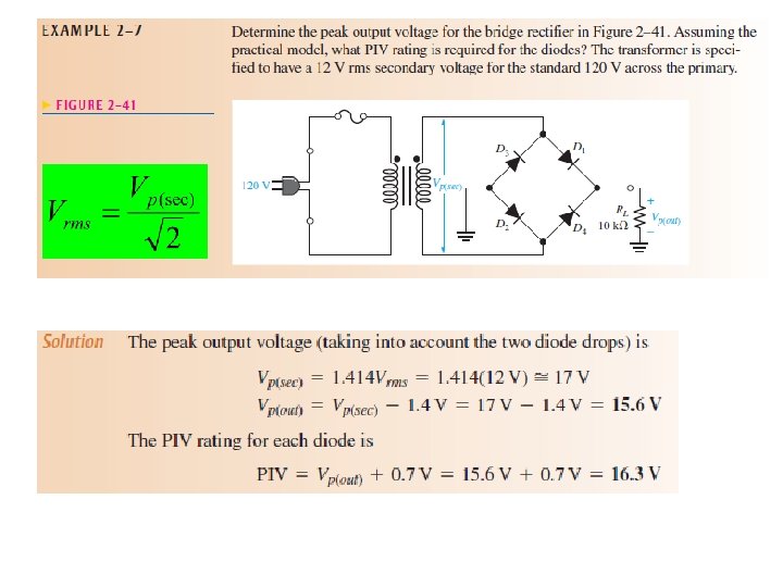
Bridge Full-Wave Rectifier Operation The bridge rectifier uses four diodes connected as shown in Figure When the input cycle is positive as in part (a), diodes D 1 and D 2 are forward-biased and conduct current in the direction shown. A voltage is developed across RL that looks like the positive half of the input cycle. During this time, diodes D 3 and D 4 are reversebiased.
Bridge Full-Wave Rectifier Operation When the input cycle is negative as in Figure 2– 38(b), diodes D 3 and D 4 are forward biased and conduct current in the same direction through RL as during the positive half-cycle. During the negative half-cycle, D 1 and D 2 are reverse-biased. A full-wave rectified output voltage appears across RL as a result of this action.
Bridge Rectifier Looks like a Wheatstone bridge. Does not require a enter tappedtransformer. Requires 2 additional diodes and voltage drop is double. Neglecting the diode drops, the secondary voltage appears across the load resistor. If these diode drops are taken into account, the output voltage is
POWER SUPPLY FILTERS AND REGULATORS The small amount of fluctuation in the filter output voltage is called ripple.
Capacitor-Input Filter
Ripple Voltage The variation in the capacitor voltage due to the charging and discharging is called the ripple voltage. Generally, ripple is undesirable; thus, the smaller the ripple, the better the filtering action For a given input frequency, the output frequency of a full-wave rectifier is twice that of a half-wave rectifier, as illustrated in Figure. This makes a full-wave rectifier easier to filter because of the shorter time between peaks.
Ripple Factor The ripple factor (r) is an indication of the effectiveness of the filter and is defined as For a full-wave rectifier with a capacitor-input filter, approximations for the peak-to-peak ripple voltage, Vr(pp), and the dc value of the filter output voltage, VDC, are given in the following equations. The variable Vp(rect) is the unfiltered peak rectified voltage. Notice that if RL or C increases, the ripple voltage decreases and the dc voltage increases.