Recommendation from impedance B Salvant on behalf of

Recommendation from impedance B. Salvant on behalf of BE-ABP/HSC section and impedance WG

With the help of Vincent Baglin
 •")
Summary of guidelines (extracted from vacuum CAS 2017) •

Main topics • Triplet bellows already agreed at WP 2 and TCC for deformable bellow • VAX area more unshielded bellows • Specification for 2. 5 mm transverse displacement in the LSS need for deformable RF bridge? • 5 th axis abandoned? good news for some bellows! • Baseline: amorphous carbon coating on triplets, corrector package, D 1, D 2 and Q 4 (and maybe TAXS? ) already dealt with • Is LESS an option? The impact there could be large due to the low conductivity (up to a factor 16 less compared to cold copper) and the large thickness (1 micron) • More iterations needed

Triplet bellows • Recommended for approval at TCC on Sept 2016

Longitudinal low frequency impedance Simplified model without fingers 15 o 1% of full HL-LHC impedance New with 15 degrees Old Assuming 32 shieldings with 65 mm radius Large contribution compared to current shielding type (estimated a factor 3. 5 increase) Would amount to 0. 3% of total impedance Going to 30 degrees for all shieldings would reach 1% of full HL-LHC impedance 6

Transverse low frequency impedance Simplified model without fingers 15 o 1% of full HL-LHC impedance New with 15 degrees old Assuming 32 shieldings with 65 mm radius at 12 km beta function Large contribution compared to current shielding type (estimated a factor 3. 5 increase) Would amount to 0. 5% of the total LHC impedance Increase to 30 degrees reaches 1. 5 % of the full HL-LHC impedance 7 Risk to increase beyond 15 degrees, in fact we already said it should be reduced.

Main topics • Triplet bellows already agreed at WP 2 and TCC for deformable bellow • VAX area more unshielded bellows • Specification for 2. 5 mm transverse displacement in the LSS need for deformable RF bridge? • 5 th axis abandoned? good news for some bellows! • Baseline: amorphous carbon coating on triplets, corrector package, D 1, D 2 and Q 4 (and maybe TAXS? ) already dealt with • Is LESS an option? The impact there could be large due to the low conductivity (up to a factor 16 less compared to cold copper) and the large thickness (1 micron) • More iterations needed
")
VAX area Unshielded bellows requested 12 bellows in total (3 per IP per side) Why step in radius? Is that “only” for standard valve?
 Expensive in terms of impedance Management")
Impedance cost of bellows (formula of K. Ng) Expensive in terms of impedance Management should decide

Main topics • Triplet bellows already agreed at WP 2 and TCC for deformable bellow • VAX area more unshielded bellows • Specification for 2. 5 mm transverse displacement in the LSS need for deformable RF bridge? • 5 th axis abandoned? good news for some bellows! • Baseline: amorphous carbon coating on triplets, corrector package, D 1, D 2 and Q 4 (and maybe TAXS? ) already dealt with • Is LESS an option? The impact there could be large due to the low conductivity (up to a factor 16 less compared to cold copper) and the large thickness (1 micron) • More iterations needed

Different transitions 11 additional bellows with deformable fingers

Deformable fingers everywhere? ? ? Avoid cavity!

Different transitions 11 additional bellows with deformable fingers per IP per side? Is expected to be very expensive in terms of impedance if the angle can not be kept flat

Main topics • Triplet bellows already agreed at WP 2 and TCC for deformable bellow • VAX area more unshielded bellows • Specification for 2. 5 mm transverse displacement in the LSS need for deformable RF bridge? • 5 th axis abandoned? good news for some bellows! • Baseline: amorphous carbon coating on triplets, corrector package, D 1, D 2 and Q 4 (and maybe TAXS? ) already dealt with • Is LESS an option? The impact there could be large due to the low conductivity (up to a factor 16 less compared to cold copper) and the large thickness (1 micron) • More iterations needed

Carbon coating • Carbon coating: 500 nm • IT, CP, D 1, D 2 and Q 4. Also maybe on TAXS • Same copper thickness as LHC.

Update on new triplet beam screen impedance B. Salvant, N. Wang, C. Zannini 14 th December 2015 Acknowledgments: N. Biancacci, R. de Maria, E. Métral, N. Mounet, N. Kos Agenda: Ø Impact of coating on the new triplet beam screen Ø Impact of coating on the current beam screen Ø Impact of various weld scenarios of weld of new triplets

Resistive wall impedance of the new beam screens • Without Coating • With Coating • 5 layers structure • • • Updated Thanks to Nicolo Biancacci’s measurements • 3 layers structure 1 st layer (a. C) • • • 2 nd layer (Ti) 3 rd layer (Cu) 4 th layer (St. St) 5 th layer (Vacuum) 1 st layer (Cu) 2 nd layer (St. St) 3 rd layer (Vacuum) Material σel [S/m] εr Thickness [µm] a. C coating 400 5. 4 0. 5 Titanium coating 4*105 1 0. 1 Copper 109 1 50 Stainless steel 1. 35 106 1 1000 Vacuum 0 1 Infinity
 Magnet Cold")
Geometries of the Hi-Lumi IR 1 and IR 5 beam screens (triplet) Magnet Cold bore ID (mm) Beam screen ID between flats (mm) Beam screen length (m) Q 1 139 99. 7/99. 7 11 Q 2 a 139 10. 2 Q 2 b 139 119. 7/111. 7 Q 3 139 119. 7/111. 7 11 CP 139 119. 7/111. 7 7. 3 D 1 139 119. 7/111. 7 8. 3 DFXJ 139 119. 7/111. 7 3. 7 D 2 95 87/78 13. 5 Q 4 80. 8 73. 8/63. 8 9. 5 10. 2 Info from N. Kos
 (2 D calculation with")
Longitudinal impedance of beam screen in triplets (IR 1&IR 5) (2 D calculation with Impedance. Wake 2 D – N. Mounet) Significant impact of coating on imaginary part Longitudinal effective impedance of the beam screen multiplied by 3 because of the coating. Still expected to be in the background of the total LHC impedance (~90 m. Ohm)
 (2 D calculation with")
Transverse impedance of beam screen in triplets (IR 1&IR 5) (2 D calculation with Impedance. Wake 2 D – N. Mounet) For lattice version V 1. 2 beta*=15 cm/15 cm Significant impact of coating on imaginary part Vertical effective impedance of the beam screen increased by 70% because of the coating. Still expected to be in the background of the total LHC impedance (~20 MOhm/m)
 For")
Impact of coating on the current beam screen (IR 2 and IR 8) For lattice version V 1. 2 beta*=15 cm/15 cm Info from N. Kos Magnet Beam screen ID (mm) Q 1 40. 4/50. 0 7. 9 181 132 Q 2+Q 3 50. 4/60. 0 61. 0/70. 6 23. 9 300 340 2. 7+10. 9 328 309 CP+D 1 Beam screen Average length (m) betax (m) Average betay (m) Significant impact of coating on imaginary part Longitudinal effective impedance comparable with the impedance of the new beam screen. Transverse effective impedance is about 1/8 of the new beam screen impedance.
 For")
Impact of coating on the current beam screen (IR 2 and IR 8) For lattice version V 1. 2 beta*=15 cm/15 cm Info from N. Kos Magnet Beamscreen ID (mm) Length (m) Q 1 Q 2+Q 3 CP+D 1 D 2 Q 4 Q 5 (2 L & 8 R) Q 5 (2 R & 8 L) Q 6 40. 4/50. 0 50. 4/60. 0 61. 0/70. 6 56. 2/65. 8 50. 4/60. 6 50. 4/60. 0 37. 6/47. 2 7. 9 23. 9 2. 7+10. 9 10. 7 12. 1 11. 8 10. 9 Betax_ave (m) Betay_ave (m) 181 300 328 170 146 93 112 146 132 340 309 160 151 132 121 108 Longitudinal effective impedance comparable with the impedance of the new beam screen. Transverse effective impedance is about 1/10 of the new beam screen impedance.

Conclusion for coating • Small impact expected on impedance of coating the new beam screens or the whole LLS for IR 1 and IR 5. • Same level of longitudinal impedance contribution by coating the current beam screen in IR 2 and IR 8. The transverse impedance contribution is much lower than the new beam screen impedance. IP 1/IP 5 IR 2/IR 8 Element (ZL/n) [Ohm] Zy [k. Ohm/m] Triplets 6. 0 E-5 24. 3 6. 0 E-5 3. 1 LSS 8. 4 E-5 27. 7 1. 3 E-4 5. 3

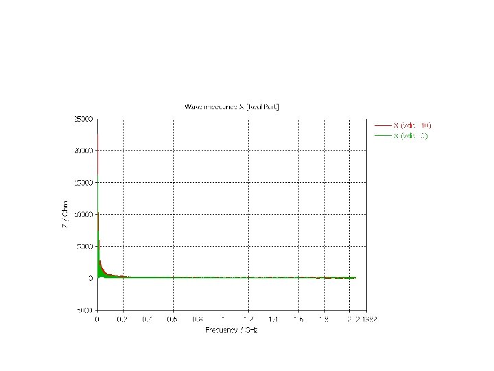
New Y chamber Old New Larger diameters lower frequency for modes but also lower resistive wall

Lower frequencies and lower impact due to taper IN (and of course taper OUT – not shown). No visible significant mode.
 slightly higher (0. 03 instead of 0. 02 m. Ohm) still negligible")
Im(Zeff_long/n) slightly higher (0. 03 instead of 0. 02 m. Ohm) still negligible
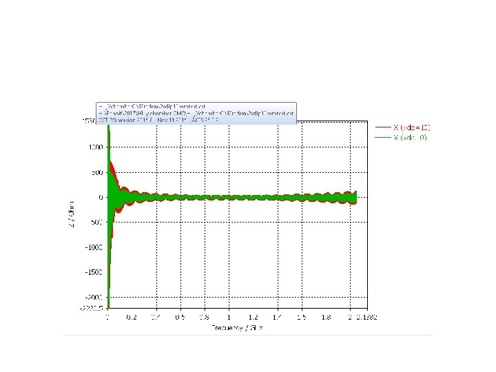

Conclusions • Geometry of the Y chamber already well optimized • No significant mode or effective contribution

Conclusions and next steps • Significant amount of additional bellows without shielding and with deformable fingers, in addition to what was already approved large cost expected in terms of impedance need to know what is the operational angle of these fingers if significant transverse offsets are needed. • More iterations are needed with all the information provided by Vincent

 Element Max betax/betay")
Compare between different Optics (IR 1, IR 5 new beam screens) Element Max betax/betay [m/m] ZT, eff 1 without ZT, eff 2 with a. C ZT, eff 2 -ZT, eff 1 a. C coating [k. Ohm/m] Collision Round 21758/21721 35. 7 60. 0 24. 3 Collision Flat 43154/43281 45. 5 76. 4 30. 9 Presqueeze optics 6776/6780 11. 4 19. 2 7. 8 VDM optics 30 m 618/599 0. 6 1. 0 0. 4
 For lattice version V 1.")
Effect from coating all LSS (IR 1, IR 5) For lattice version V 1. 2 beta*=15 cm/15 cm Element Length [m] Zl, eff 1 without a. C Zl, eff 2 with a. C coating [Ohm] Zl, eff 2 -Zl, eff 1 [Ohm] Triplets -- 3. 6 E-5 9. 6 E-5 6. 0 E-5 Q 5 8. 5 6. 8 E-6 1. 8 E-5 1. 1 E-5 Q 6 7. 1 7. 6 E-6 2. 0 E-5 1. 3 E-5 LSS -- 5. 1 E-5 13. 5 E-5 8. 4 E-5 Element Length [m] Beam screen betay_ave [m] ID between flats (mm) ZT, eff 1 without ZT, eff 2 with a. C coating [k. Ohm/m] ZT, eff 2 -ZT, eff 1 [k. Ohm/m] Triplets -- -- -- 35. 7 60. 0 24. 3 Q 5 8. 5 50. 4/60 900 2. 8 4. 7 1. 9 Q 6 7. 1 37. 6/47. 2 345 2. 2 3. 7 1. 5 LSS -- -- -- 40. 7 68. 4 27. 7 Longitudinal/transverse impedance of beam screen increased by 40%/14% Still expected to be in the background of the total LHC impedance.
- Slides: 34