
Receiver Performance Transmitted BW Contest Fatigue Rob Sherwood
Receiver Performance Transmitted BW Contest Fatigue Rob Sherwood NCØB Limitations to a better contest score may not always be obvious. Sherwood Engineering
• What is important in a contest environment? • Good Dynamic Range to hear weak signals in the presence of near-by strong signals. • Be a good neighbor: i. e. Have a clean signal. • Subtle factors affect receiver performance, but are never tested or even discussed by ARRL. • You need a better receiver for CW than for SSB. • New technology is not automatically better. • Minimize fatigue factors to maximize you score.
What Parameter is Most Important for a CW Contester? • Close-in Dynamic Range (DR 3) • (We have to know the noise floor to calculate Dynamic Range)
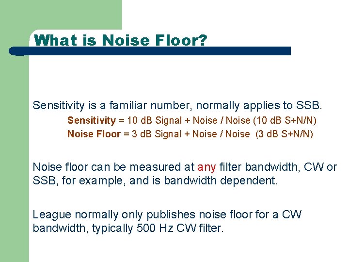
What is Noise Floor? Sensitivity is a familiar number, normally applies to SSB. Sensitivity = 10 d. B Signal + Noise / Noise (10 d. B S+N/N) Noise Floor = 3 d. B Signal + Noise / Noise (3 d. B S+N/N) Noise floor can be measured at any filter bandwidth, CW or SSB, for example, and is bandwidth dependent. League normally only publishes noise floor for a CW bandwidth, typically 500 Hz CW filter.
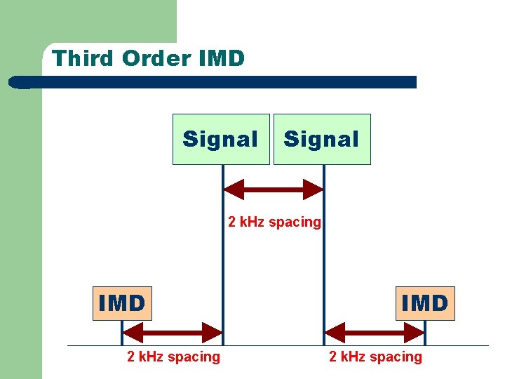
Third Order IMD Signal 2 k. Hz spacing IMD 2 k. Hz spacing
What is Dynamic Range? The range in d. B of very strong signals to very weak signals that the receiver can handle At The Same Time What is Close-in Dynamic Range vs Wide-Spaced Dynamic Range? Why is Close-in Dynamic so important for CW ops? Why is it less important for SSB operators?
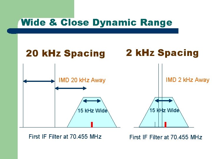
Wide & Close Dynamic Range 20 k. Hz Spacing IMD 20 k. Hz Away 15 k. Hz Wide First IF Filter at 70. 455 MHz 2 k. Hz Spacing IMD 2 k. Hz Away 15 k. Hz Wide First IF Filter at 70. 455 MHz
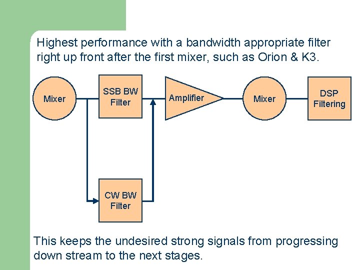
Highest performance with a bandwidth appropriate filter right up front after the first mixer, such as Orion & K 3. Mixer SSB BW Filter Amplifier Mixer DSP Filtering CW BW Filter This keeps the undesired strong signals from progressing down stream to the next stages.
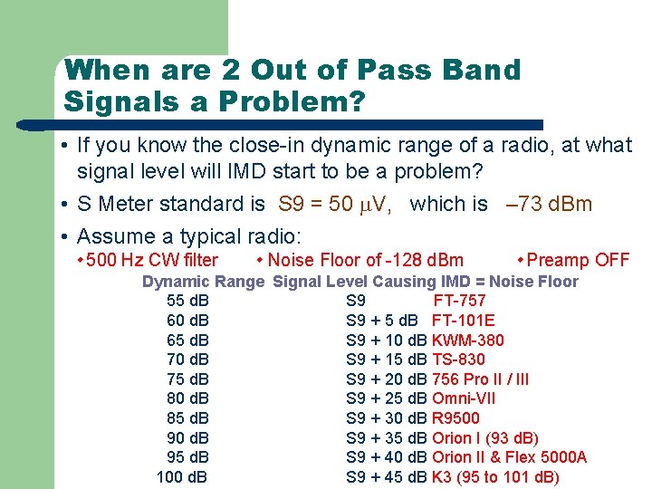
When are 2 Out of Pass Band Signals a Problem? • If you know the close-in dynamic range of a radio, at what signal level will IMD start to be a problem? • S Meter standard is S 9 = 50 V, which is – 73 d. Bm • Assume a typical radio: 500 Hz CW filter Noise Floor of -128 d. Bm Preamp OFF Dynamic Range Signal Level Causing IMD = Noise Floor 55 d. B S 9 FT-757 60 d. B S 9 + 5 d. B FT-101 E 65 d. B S 9 + 10 d. B KWM-380 70 d. B S 9 + 15 d. B TS-830 75 d. B S 9 + 20 d. B 756 Pro II / III 80 d. B S 9 + 25 d. B Omni-VII 85 d. B S 9 + 30 d. B R 9500 90 d. B S 9 + 35 d. B Orion I (93 d. B) 95 d. B S 9 + 40 d. B Orion II & Flex 5000 A 100 d. B S 9 + 45 d. B K 3 (95 to 101 d. B)
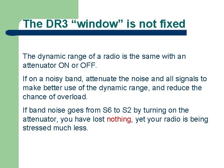
The DR 3 “window” is not fixed The dynamic range of a radio is the same with an attenuator ON or OFF. If on a noisy band, attenuate the noise and all signals to make better use of the dynamic range, and reduce the chance of overload. If band noise goes from S 6 to S 2 by turning on the attenuator, you have lost nothing, yet your radio is being stressed much less.
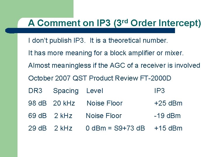
A Comment on IP 3 (3 rd Order Intercept) I don’t publish IP 3. It is a theoretical number. It has more meaning for a block amplifier or mixer. Almost meaningless if the AGC of a receiver is involved October 2007 QST Product Review FT-2000 D DR 3 Spacing Level IP 3 98 d. B 20 k. Hz Noise Floor +25 d. Bm 69 d. B 2 k. Hz Noise Floor -19 d. Bm 29 d. B 2 k. Hz 0 d. Bm = S 9+73 d. B +15 d. Bm
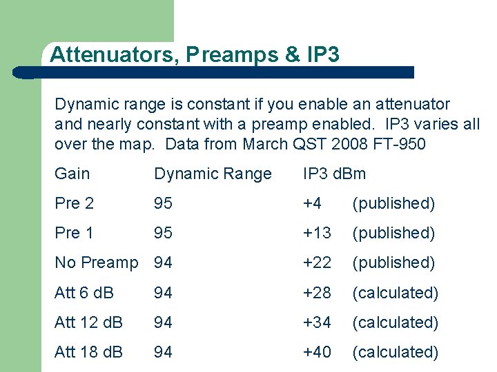
Attenuators, Preamps & IP 3 Dynamic range is constant if you enable an attenuator and nearly constant with a preamp enabled. IP 3 varies all over the map. Data from March QST 2008 FT-950 Gain Dynamic Range IP 3 d. Bm Pre 2 95 +4 (published) Pre 1 95 +13 (published) No Preamp 94 +22 (published) Att 6 d. B 94 +28 (calculated) Att 12 d. B 94 +34 (calculated) Att 18 d. B 94 +40 (calculated)
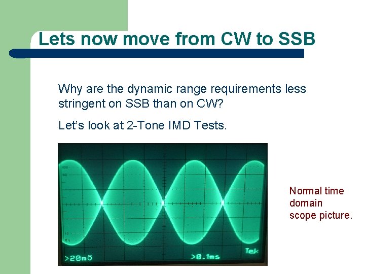
Lets now move from CW to SSB Why are the dynamic range requirements less stringent on SSB than on CW? Let’s look at 2 -Tone IMD Tests. Normal time domain scope picture.
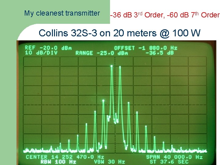
My cleanest transmitter -36 d. B 3 rd Order, -60 d. B 7 th Order Collins 32 S-3 on 20 meters @ 100 W
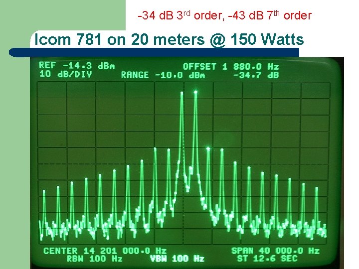
-34 d. B 3 rd order, -43 d. B 7 th order Icom 781 on 20 meters @ 150 Watts
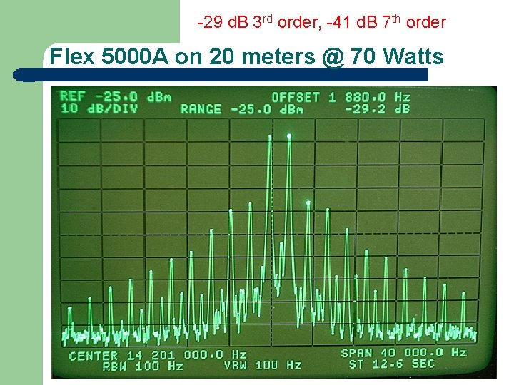
-29 d. B 3 rd order, -41 d. B 7 th order Flex 5000 A on 20 meters @ 70 Watts
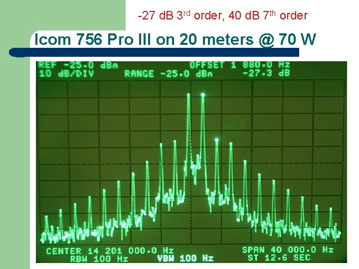
-27 d. B 3 rd order, 40 d. B 7 th order Icom 756 Pro III on 20 meters @ 70 W
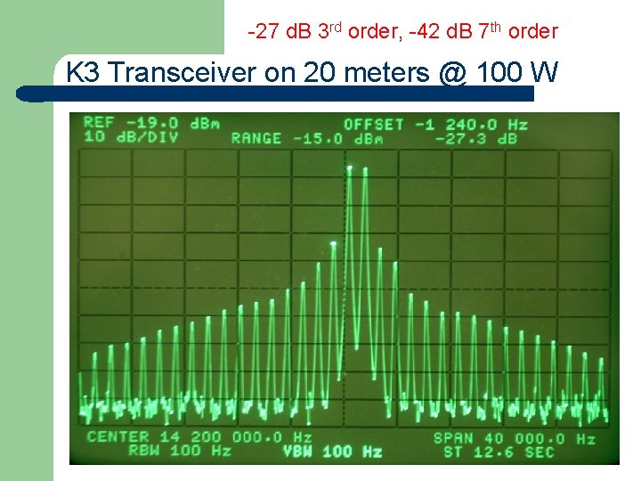
-27 d. B 3 rd order, -42 d. B 7 th order K 3 Transceiver on 20 meters @ 100 W
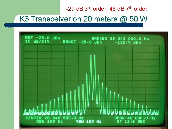
-27 d. B 3 rd order, 46 d. B 7 th order K 3 Transceiver on 20 meters @ 50 W
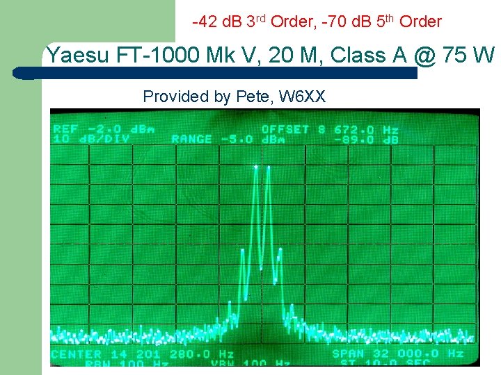
-42 d. B 3 rd Order, -70 d. B 5 th Order Yaesu FT-1000 Mk V, 20 M, Class A @ 75 W Provided by Pete, W 6 XX
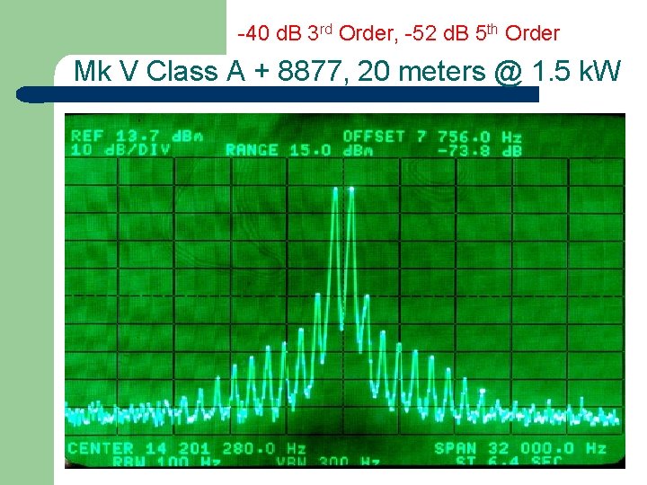
-40 d. B 3 rd Order, -52 d. B 5 th Order Mk V Class A + 8877, 20 meters @ 1. 5 k. W
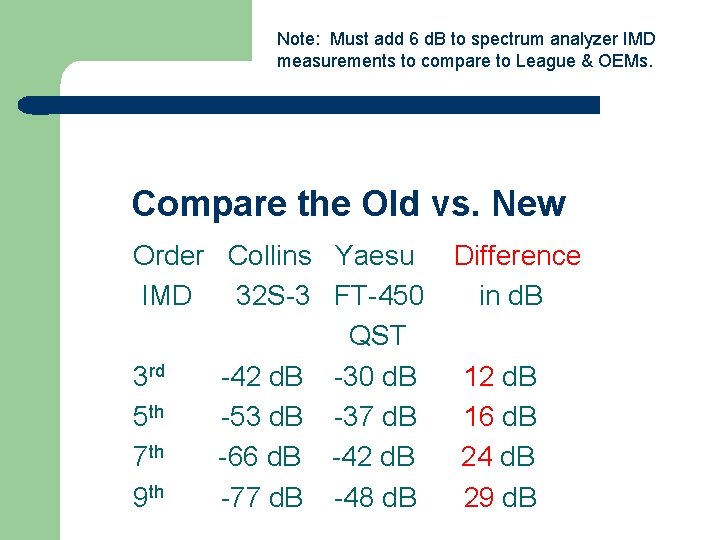
Note: Must add 6 d. B to spectrum analyzer IMD measurements to compare to League & OEMs. Compare the Old vs. New Order Collins Yaesu IMD 32 S-3 FT-450 QST 3 rd -42 d. B -30 d. B 5 th -53 d. B -37 d. B 7 th -66 d. B -42 d. B 9 th -77 d. B -48 d. B Difference in d. B 12 d. B 16 d. B 24 d. B 29 d. B
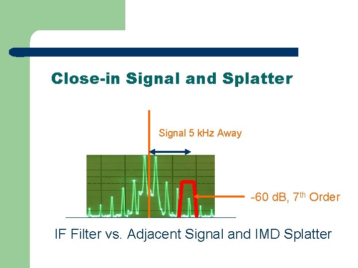
Close-in Signal and Splatter Signal 5 k. Hz Away -60 d. B, 7 th Order IF Filter vs. Adjacent Signal and IMD Splatter
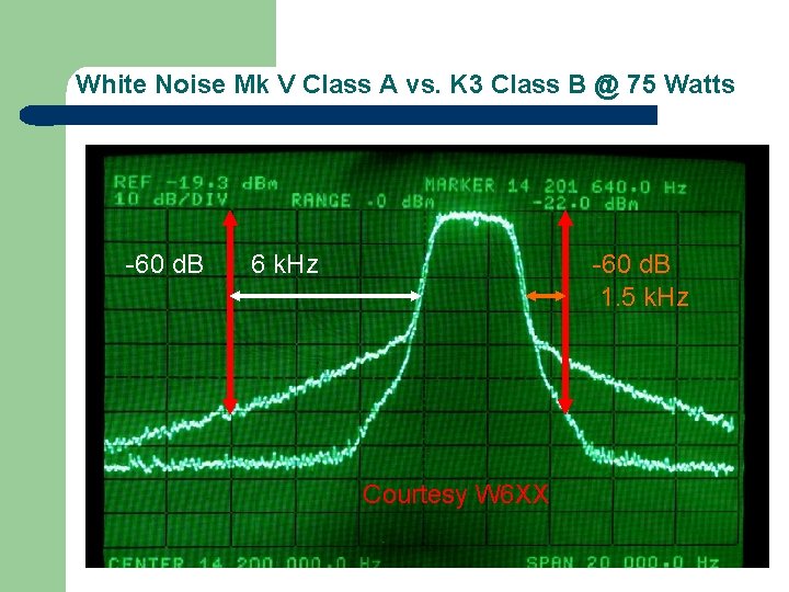
White Noise Mk V Class A vs. K 3 Class B @ 75 Watts -60 d. B 6 k. Hz -60 d. B 1. 5 k. Hz Courtesy W 6 XX
Back to CW signals We have seen how width of an SSB signal & its IMD products affects how close you can operate to another station. How does CW compare? How close can we work to a strong adjacent CW signal?
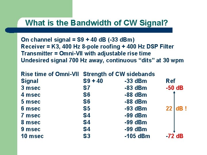
What is the Bandwidth of CW Signal? On channel signal = S 9 + 40 d. B (-33 d. Bm) Receiver = K 3, 400 Hz 8 -pole roofing + 400 Hz DSP Filter Transmitter = Omni-VII with adjustable rise time Undesired signal 700 Hz away, continuous “dits” at 30 wpm Rise time of Omni-VII Signal 3 msec 4 msec 5 msec 6 msec 7 msec 8 msec 9 msec 10 msec Strength of CW sidebands S 9 + 40 -33 d. Bm S 7 -83 d. Bm S 6 -88 d. Bm S 5 -93 d. Bm S 4 -99 d. Bm S 3 -105 d. Bm Ref -50 d. B 22 d. B ! -72 d. B
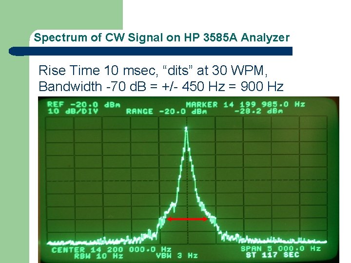
Spectrum of CW Signal on HP 3585 A Analyzer Rise Time 10 msec, “dits” at 30 WPM, Bandwidth -70 d. B = +/- 450 Hz = 900 Hz
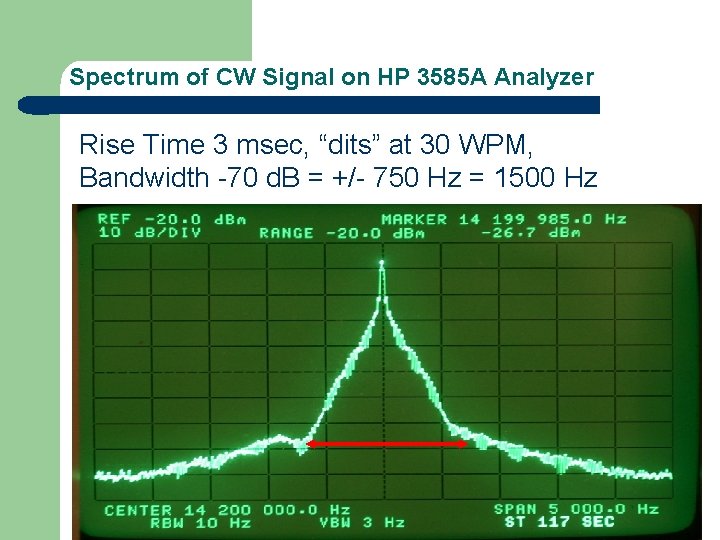
Spectrum of CW Signal on HP 3585 A Analyzer Rise Time 3 msec, “dits” at 30 WPM, Bandwidth -70 d. B = +/- 750 Hz = 1500 Hz
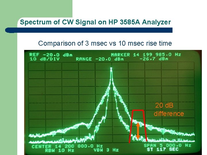
Spectrum of CW Signal on HP 3585 A Analyzer Comparison of 3 msec vs 10 msec rise time 20 d. B difference
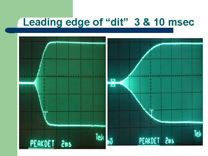
Leading edge of “dit” 3 & 10 msec
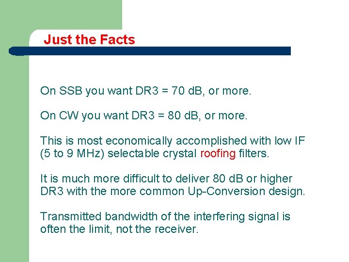
Just the Facts On SSB you want DR 3 = 70 d. B, or more. On CW you want DR 3 = 80 d. B, or more. This is most economically accomplished with low IF (5 to 9 MHz) selectable crystal roofing filters. It is much more difficult to deliver 80 d. B or higher DR 3 with the more common Up-Conversion design. Transmitted bandwidth of the interfering signal is often the limit, not the receiver.
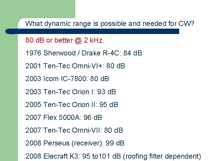
What dynamic range is possible and needed for CW? 80 d. B or better @ 2 k. Hz. 1976 Sherwood / Drake R-4 C: 84 d. B 2001 Ten-Tec Omni-VI+: 80 d. B 2003 Icom IC-7800: 80 d. B 2003 Ten-Tec Orion I: 93 d. B 2005 Ten-Tec Orion II: 95 d. B 2007 Flex 5000 A: 96 d. B 2007 Ten-Tec Omni-VII: 80 d. B 2008 Perseus (receiver): 99 d. B 2008 Elecraft K 3: 95 to 101 d. B (roofing filter dependent)
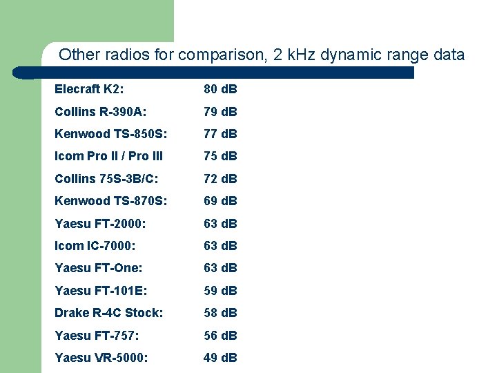
Other radios for comparison, 2 k. Hz dynamic range data Elecraft K 2: 80 d. B Collins R-390 A: 79 d. B Kenwood TS-850 S: 77 d. B Icom Pro II / Pro III 75 d. B Collins 75 S-3 B/C: 72 d. B Kenwood TS-870 S: 69 d. B Yaesu FT-2000: 63 d. B Icom IC-7000: 63 d. B Yaesu FT-One: 63 d. B Yaesu FT-101 E: 59 d. B Drake R-4 C Stock: 58 d. B Yaesu FT-757: 56 d. B Yaesu VR-5000: 49 d. B
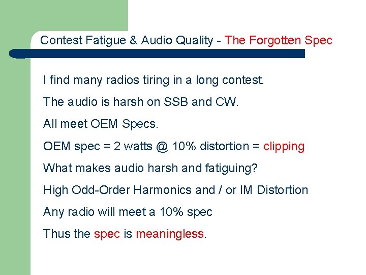
Contest Fatigue & Audio Quality - The Forgotten Spec I find many radios tiring in a long contest. The audio is harsh on SSB and CW. All meet OEM Specs. OEM spec = 2 watts @ 10% distortion = clipping What makes audio harsh and fatiguing? High Odd-Order Harmonics and / or IM Distortion Any radio will meet a 10% spec Thus the spec is meaningless.
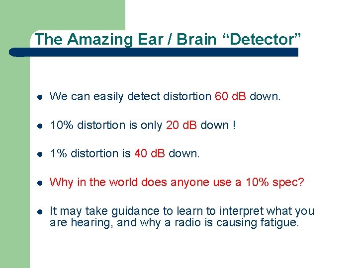
The Amazing Ear / Brain “Detector” l We can easily detect distortion 60 d. B down. l 10% distortion is only 20 d. B down ! l 1% distortion is 40 d. B down. l Why in the world does anyone use a 10% spec? l It may take guidance to learn to interpret what you are hearing, and why a radio is causing fatigue.
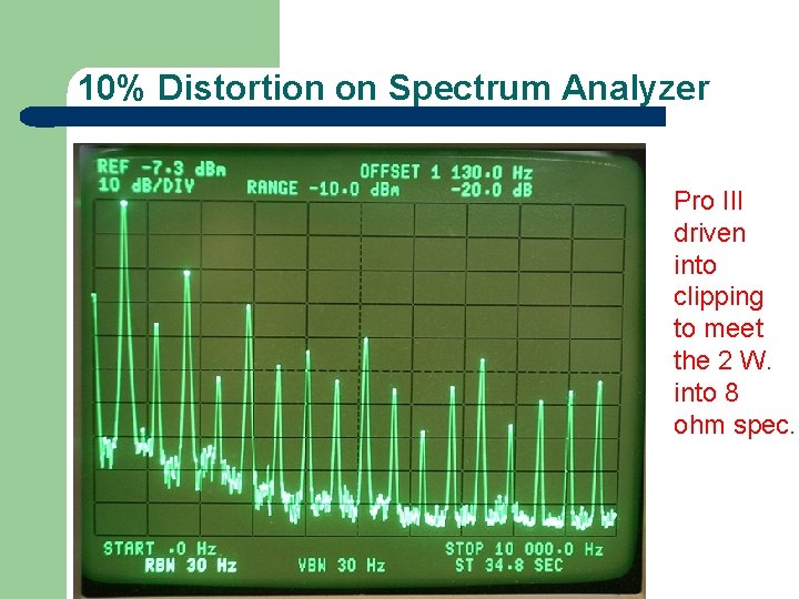
10% Distortion on Spectrum Analyzer Pro III driven into clipping to meet the 2 W. into 8 ohm spec.
Contest Fatigue & New Technologies Laboratory tests are important, but radios also need to be evaluated in a contest environment. I use two operating positions to compare a “reference radio” to a “test” or “evaluation” radio, going back and forth between station A and B during a contest. Interesting problems have come to light in on-air A / B comparisons.
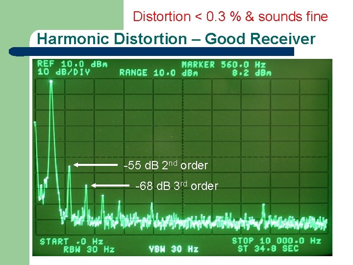
Distortion < 0. 3 % & sounds fine Harmonic Distortion – Good Receiver -55 d. B 2 nd order -68 d. B 3 rd order
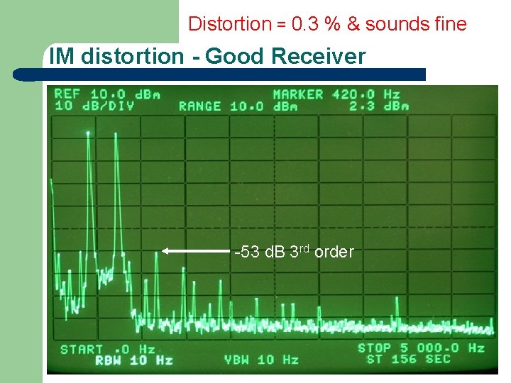
Distortion = 0. 3 % & sounds fine IM distortion - Good Receiver -53 d. B 3 rd order
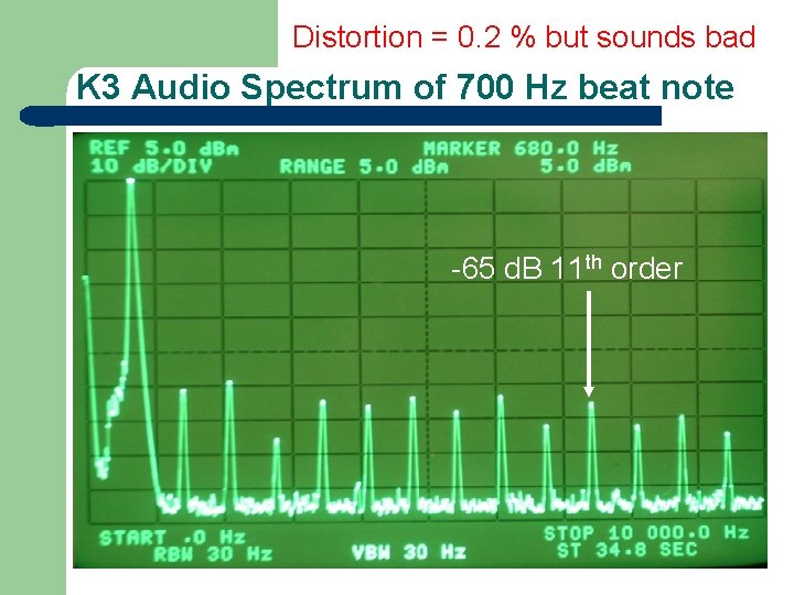
Distortion = 0. 2 % but sounds bad K 3 Audio Spectrum of 700 Hz beat note -65 d. B 11 th order
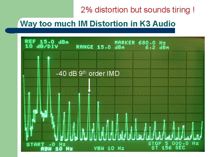
2% distortion but sounds tiring ! Way too much IM Distortion in K 3 Audio -40 d. B 9 th order IMD
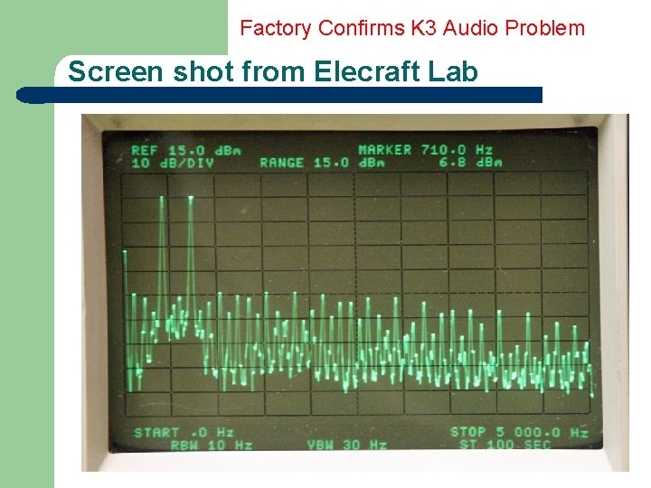
Factory Confirms K 3 Audio Problem Screen shot from Elecraft Lab
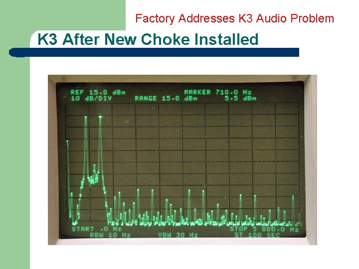
Factory Addresses K 3 Audio Problem K 3 After New Choke Installed
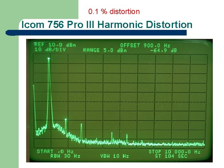
0. 1 % distortion Icom 756 Pro III Harmonic Distortion
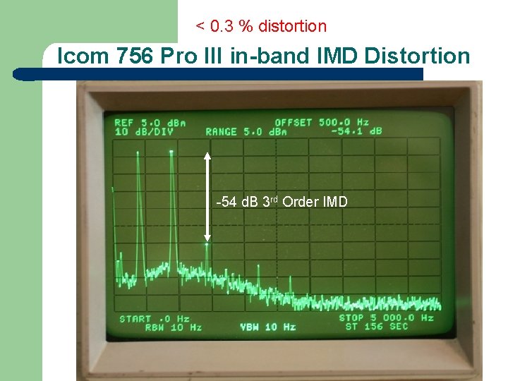
< 0. 3 % distortion Icom 756 Pro III in-band IMD Distortion -54 d. B 3 rd Order IMD
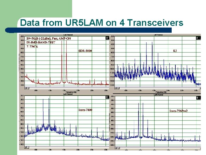
Data from UR 5 LAM on 4 Transceivers
How to Prove what you can Hear? l Some problems are “dynamic”, and not easy to measure with a steady-state signal generator or two. l One solution: A Fast Fourier Transform or “FFT” spectrum analyzer for near real time analysis.
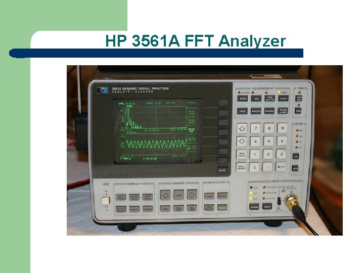
HP 3561 A FFT Analyzer
QRN Sneaks Through l At least two modern DSP transceivers do not cope well with QRN (static) crashes. l If you do any low-band contesting, you know how fatiguing QRN can be. l I was hearing QRN crashes 15 X the bandwidth of the CW filter in my headphones.
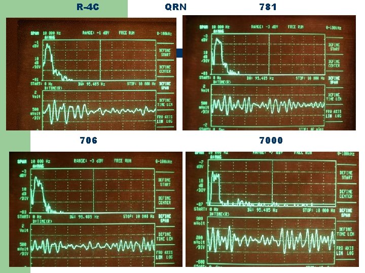
R-4 C 706 QRN 781 7000
How to Approximate QRN in the Lab? l Used multiple tones to approximate broadband QRN static crash. l QRN = hundreds of tones.
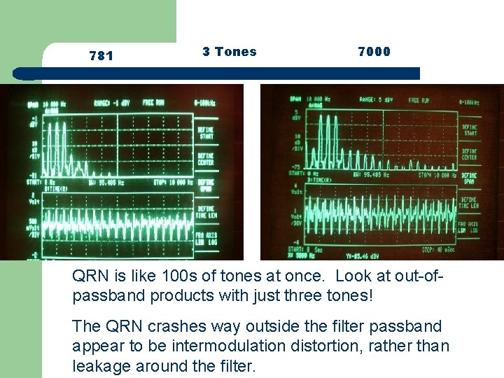
781 3 Tones 7000 QRN is like 100 s of tones at once. Look at out-ofpassband products with just three tones! The QRN crashes way outside the filter passband appear to be intermodulation distortion, rather than leakage around the filter.
Another Dynamic Fatigue Problem l In January 2009 CQ 160 meter CW contest, I went back and forth between a 20 years old analog IC-781 and a 1 year old IC-756 Pro III DSP radio. l I could not listen to the Pro III for more than an hour at a time before my ears were complaining due to CW AGC attack distortion.
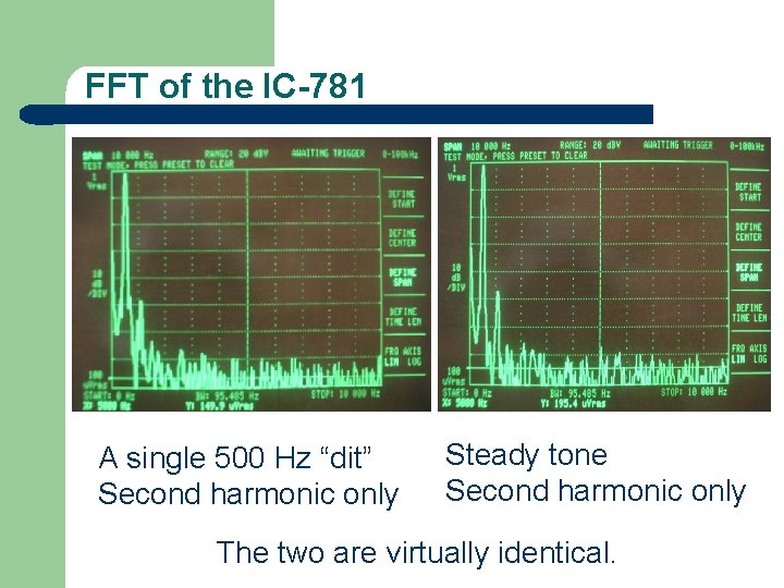
FFT of the IC-781 A single 500 Hz “dit” Second harmonic only Steady tone Second harmonic only The two are virtually identical.
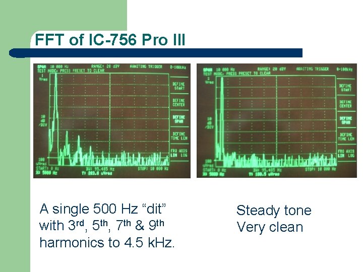
FFT of IC-756 Pro III A single 500 Hz “dit” with 3 rd, 5 th, 7 th & 9 th harmonics to 4. 5 k. Hz. Steady tone Very clean
AGC Impulse Noise Anomaly Most new radios since 2003 exaggerate impulse noise. The exceptions: Elecraft K 3, Flex 5000 & Perseus Programmed DSP to ignore a tick, click or pop. Elecraft calls it the Sherwood Test.
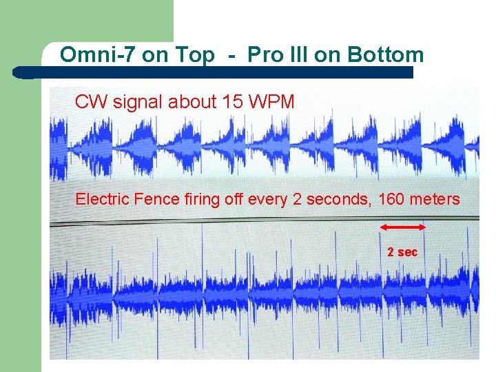
Omni-7 on Top - Pro III on Bottom CW signal about 15 WPM Electric Fence firing off every 2 seconds, 160 meters 2 sec
Listen to 30 second audio clip l l l Audio Icom 756 Pro III 160 meters, 4 PM, Dec 13, 2008 Electric fence & CW signals KV 4 FZ calling DX station Note volume level relatively constant
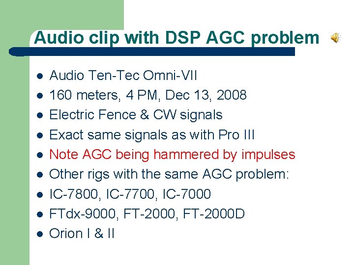
Audio clip with DSP AGC problem l l l l l Audio Ten-Tec Omni-VII 160 meters, 4 PM, Dec 13, 2008 Electric Fence & CW signals Exact same signals as with Pro III Note AGC being hammered by impulses Other rigs with the same AGC problem: IC-7800, IC-7700, IC-7000 FTdx-9000, FT-2000 D Orion I & II
The Challenge = Get OEMs to Listen In a 24 hour or 48 hour contest, you need every edge. High Dynamic Range Receiver Good Speech Processor on SSB Good Antennas. But Your Brain Can Get “Fried” due to operator fatigue. Audio problems / artifacts are a factor in that fatigue. 10% distortion specs are ridiculous. Dynamic distortion is not even evaluated.
Conclusions Ø Contesters – DXers – Pileup operators need a good receiver for SSB and an even better receiver for CW. Ø Designing good DSP is very difficult. Ø Subtle issues are being complete overlooked. Ø Feedback to OEMs is critical if products are going to improve.

Sherwood Engineering http: //www. sherwood-engineering. com http: //www. NC 0 B. com
- Slides: 62