
REALIGNMENT OF CURVES 1 APEX DISTANCE OPTION I







- Slides: 52
REALIGNMENT OF CURVES 1
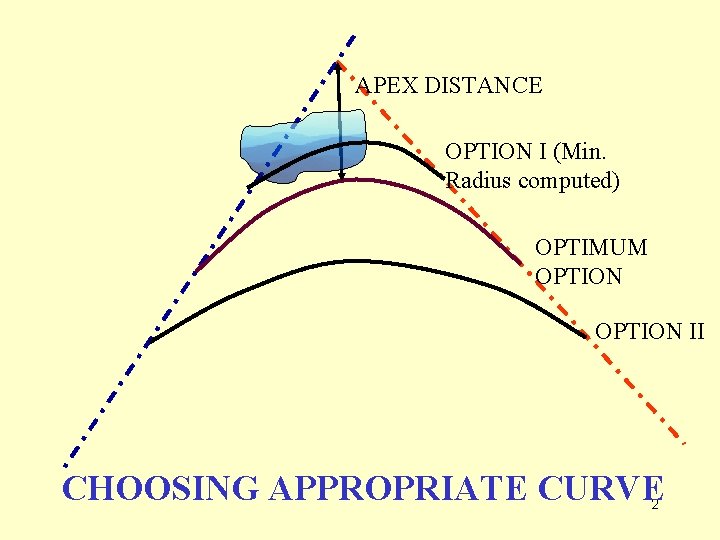
APEX DISTANCE OPTION I (Min. Radius computed) OPTIMUM OPTION II CHOOSING APPROPRIATE CURVE 2
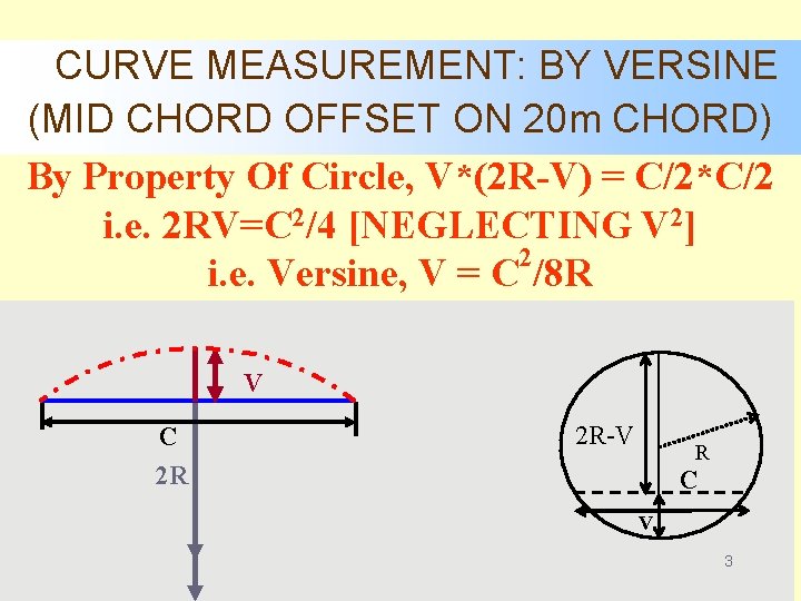
CURVE MEASUREMENT: BY VERSINE (MID CHORD OFFSET ON 20 m CHORD) By Property Of Circle, V*(2 R-V) = C/2*C/2 i. e. 2 RV=C 2/4 [NEGLECTING V 2] 2 i. e. Versine, V = C /8 R V C 2 R 2 R-V R C V 3
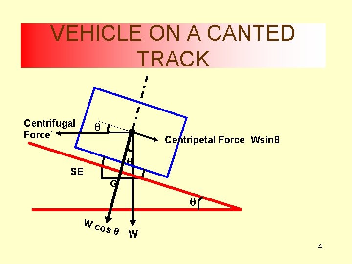
VEHICLE ON A CANTED TRACK Centrifugal Force` θ Centripetal Force Wsinθ θ SE G θ W co sθ W 4
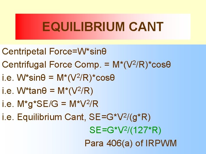
EQUILIBRIUM CANT Centripetal Force=W*sinθ Centrifugal Force Comp. = M*(V 2/R)*cosθ i. e. W*sinθ = M*(V 2/R)*cosθ i. e. W*tanθ = M*(V 2/R) i. e. M*g*SE/G = M*V 2/R i. e. Equilibrium Cant, SE=G*V 2/(g*R) SE=G*V 2/(127*R) Para 406(a) of IRPWM 5
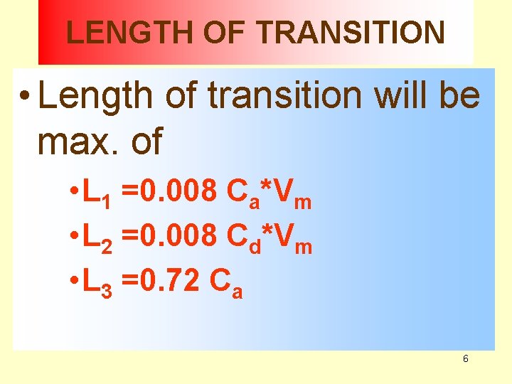
LENGTH OF TRANSITION • Length of transition will be max. of • L 1 =0. 008 Ca*Vm • L 2 =0. 008 Cd*Vm • L 3 =0. 72 Ca 6
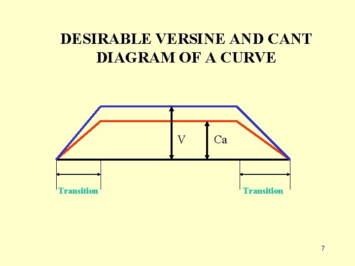
DESIRABLE VERSINE AND CANT DIAGRAM OF A CURVE V Transition Ca Transition 7
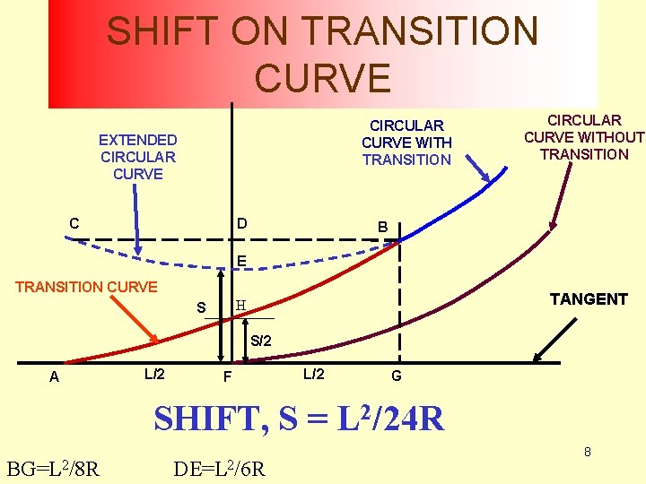
SHIFT ON TRANSITION CURVE CIRCULAR CURVE WITH TRANSITION EXTENDED CIRCULAR CURVE C D CIRCULAR CURVE WITHOUT TRANSITION B E TRANSITION CURVE TANGENT H S S/2 A L/2 F L/2 G SHIFT, S = L 2/24 R BG=L 2/8 R DE=L 2/6 R 8
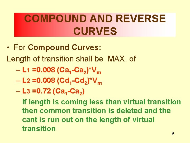
COMPOUND AND REVERSE CURVES • For Compound Curves: Length of transition shall be MAX. of – L 1 =0. 008 (Ca 1 -Ca 2)*Vm – L 2 =0. 008 (Cd 1 -Cd 2)*Vm – L 3 =0. 72 (Ca 1 -Ca 2) If length is coming less than virtual transition then common transition is deleted and the cant is run out on the length of virtual transition 9
SUGGESTED FURTHER READINGS • IRPWM CHAPTER 4 • IRICEN BOOK ON “RAILWAY CURVES” • WRITE UP WITH THE PROGRAM “REALIGNMENT OF CURVES” IN MEMBERS’ AREA OF IRICEN WEBSITE 10
• Slew v. Shift 11
WHY REQUIRED ? • Because curve geometry gets disturbed under passage of traffic as – Trains are not moving at equilibrium speed – Large horizontal forces on the rails due to slight variations in curvature and due to vehicle imperfections 12
WHAT IS MEANT BY ROC ? • Bringing the curve back to proper alignment • Doesn’t necessarily mean restoring to original alignment • Infinite number of curves are possible between same set of tangents 13
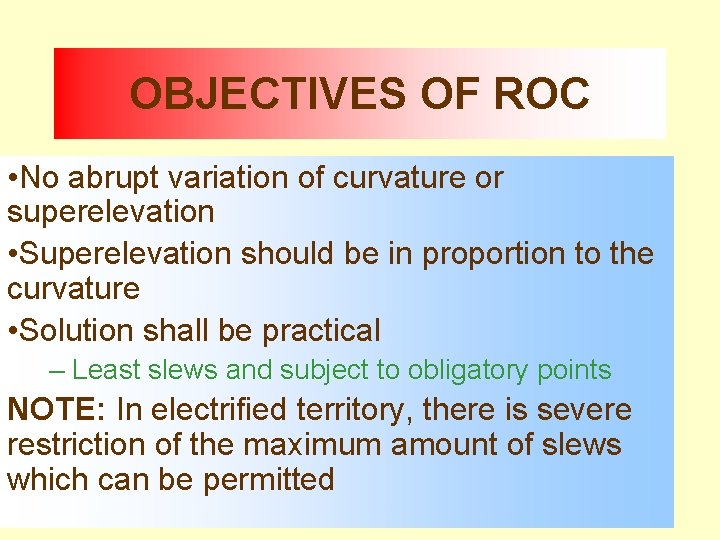
OBJECTIVES OF ROC • No abrupt variation of curvature or superelevation • Superelevation should be in proportion to the curvature • Solution shall be practical – Least slews and subject to obligatory points NOTE: In electrified territory, there is severe restriction of the maximum amount of slews which can be permitted 14
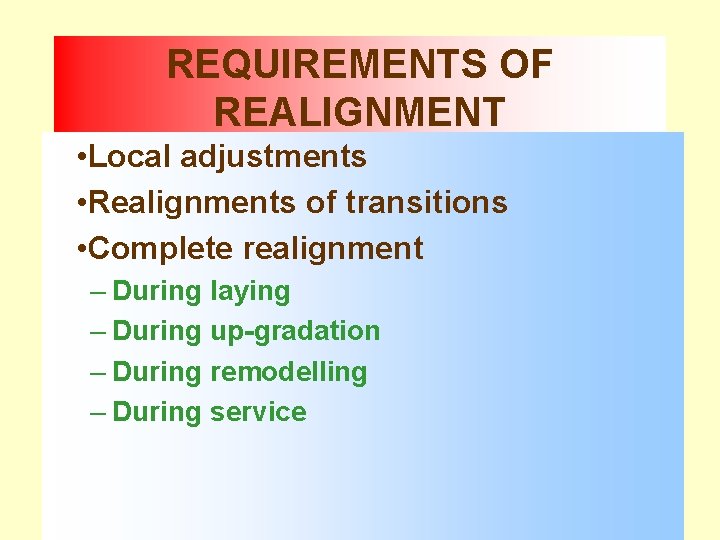
REQUIREMENTS OF REALIGNMENT • Local adjustments • Realignments of transitions • Complete realignment – During laying – During up-gradation – During remodelling – During service 15
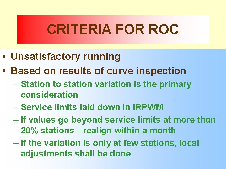
CRITERIA FOR ROC • Unsatisfactory running • Based on results of curve inspection – Station to station variation is the primary consideration – Service limits laid down in IRPWM – If values go beyond service limits at more than 20% stations—realign within a month – If the variation is only at few stations, local adjustments shall be done 16
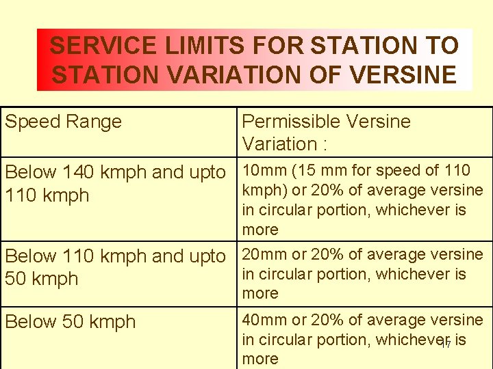
SERVICE LIMITS FOR STATION TO STATION VARIATION OF VERSINE Speed Range Permissible Versine Variation : Below 140 kmph and upto 10 mm (15 mm for speed of 110 kmph) or 20% of average versine 110 kmph in circular portion, whichever is more Below 110 kmph and upto 20 mm or 20% of average versine in circular portion, whichever is 50 kmph more Below 50 kmph 40 mm or 20% of average versine in circular portion, whichever 17 is more
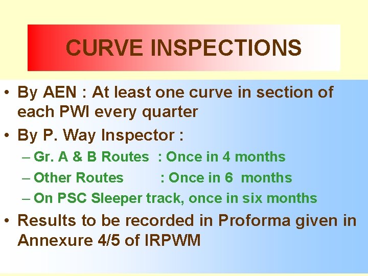
CURVE INSPECTIONS • By AEN : At least one curve in section of each PWI every quarter • By P. Way Inspector : – Gr. A & B Routes : Once in 4 months – Other Routes : Once in 6 months – On PSC Sleeper track, once in six months • Results to be recorded in Proforma given in Annexure 4/5 of IRPWM 18
STRING LINING METHOD BASIC PRINCIPLES 19
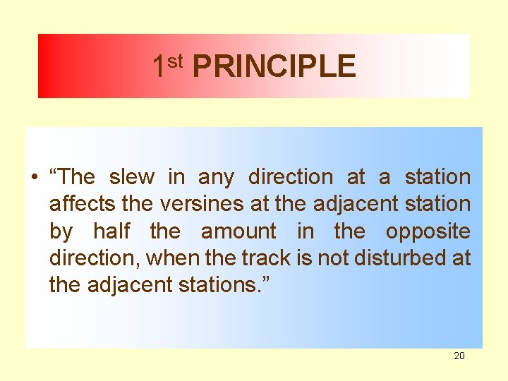
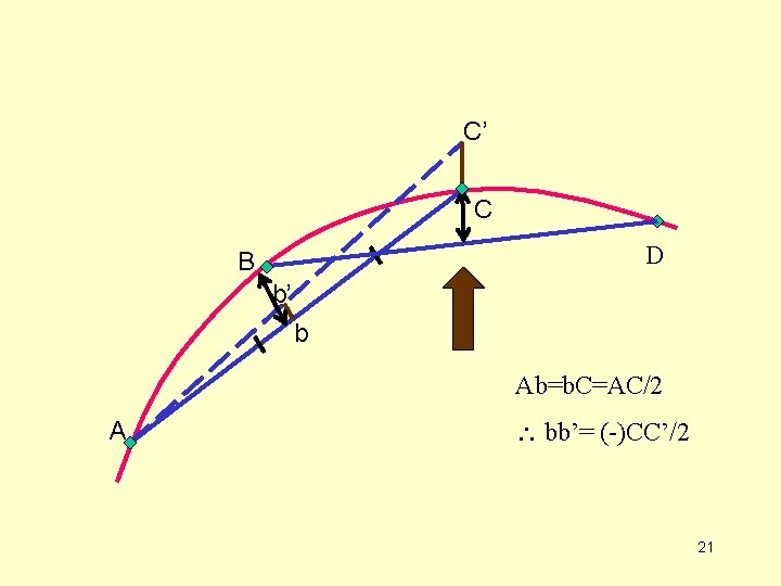
1 st PRINCIPLE • “The slew in any direction at a station affects the versines at the adjacent station by half the amount in the opposite direction, when the track is not disturbed at the adjacent stations. ” 20
C’ C D B b’ b Ab=b. C=AC/2 A bb’= (-)CC’/2 21
2 nd PRINCIPLE • “The sum total of versines on equal chords of any number of curves between the same tangents are equal. ” 22
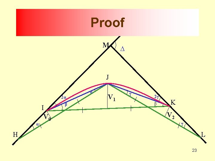
Proof M ∆ J α α I V 0 2α β V 1 γ 2γ β K V 2 γ H L 23
Proof • • V 0=α*(c/2) V 1=β*(c/2) V 2=γ*(c/2) ΣV=V 0+V 1+V 2= (α+ β+ γ)*(c/2) In ∆IMK, <MIK+<MKI=Deflection Angle i. e. ∆= (2α+ β) + (2γ+ β)=2(α+ β+ γ) i. e. ∆=2(ΣV)*(2/c), ΣV=∆*c/4 i. e. If station units are constant and ∆ does not change, the sum of all versines will be constant 24
COROLLARY TO 2 nd PRINCIPLE • “The chord length being equal, the sum total of the existing versines should be equal to the sum total of the proposed versines. ” 25
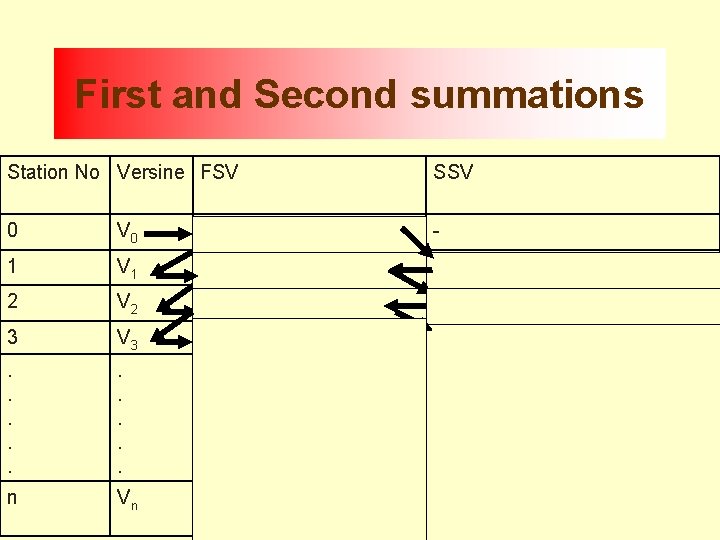
First and Second summations Station No Versine FSV SSV 0 V 0 - 1 V 0 + V 1 V 0 2 V 0 + V 1 + V 2 2* V 0 + V 1 3 V 0+ V 1+ V 2+V 3 3* V 0+2* V 1+ V 2 . . . . n Vn V 0+ V 1+ V 2 ……. +Vn-2+ n *V 0+(n-1) *V 1+ (n-2) *V 262+ …. . Vn + 2 *Vn-2+ Vn-1
3 rd PRINCIPLE • “First summation of versines represents the area of versine diagram (in station distance units) – Summation means the sum of all the items above a certain station in the table 27
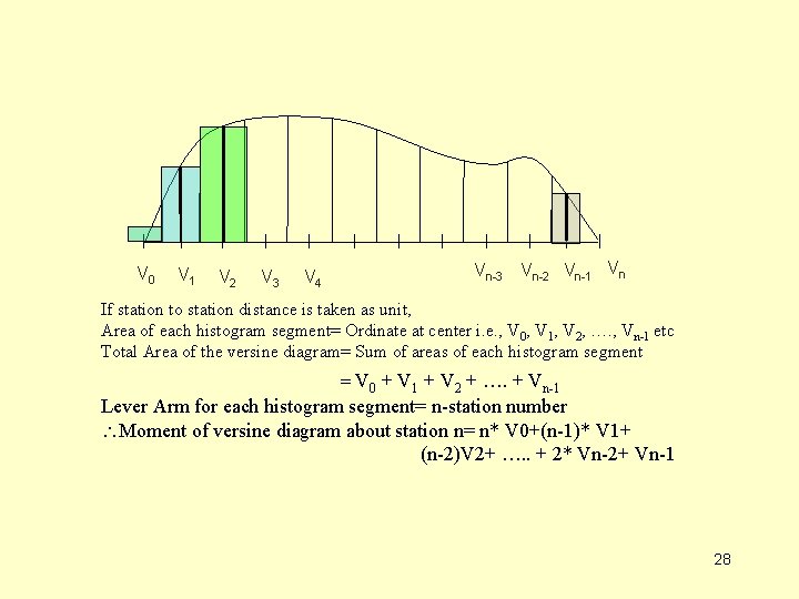
V 0 V 1 V 2 V 3 V 4 Vn-3 Vn-2 Vn-1 Vn If station to station distance is taken as unit, Area of each histogram segment= Ordinate at center i. e. , V 0, V 1, V 2, …. , Vn-1 etc Total Area of the versine diagram= Sum of areas of each histogram segment = V 0 + V 1 + V 2 + …. + Vn-1 Lever Arm for each histogram segment= n-station number Moment of versine diagram about station n= n* V 0+(n-1)* V 1+ (n-2)V 2+ …. . + 2* Vn-2+ Vn-1 28
4 th PRINCIPLE • “Second summation of versines represents the moment of versine diagram about the last station ( in station distance units). ” 29
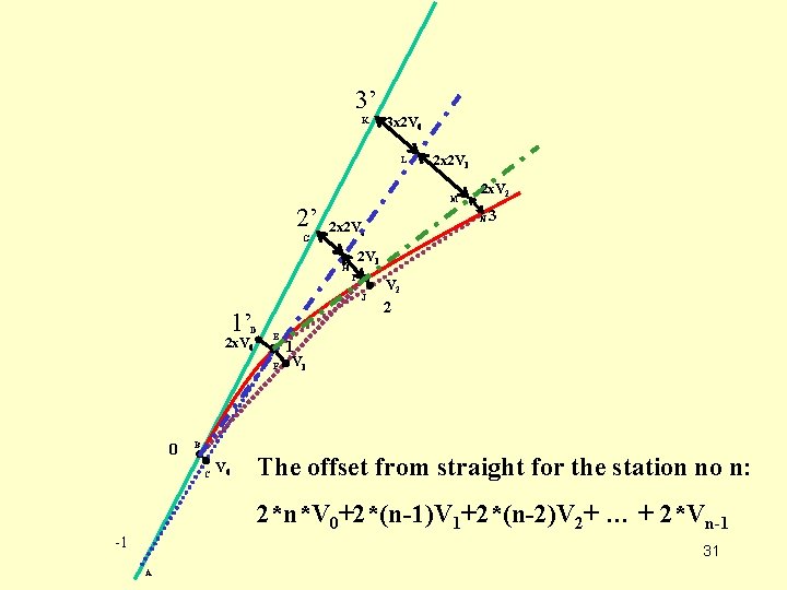
5 th PRINCIPLE • “The second summation of versine difference represents half the slew at any station” 30
3’ K 3 x 2 V 0 L 2’ G M J D E F 0 3 2 V 1 I 2 x. V 0 2 x. V 2 N 2 x 2 V 0 H 1’ 2 x 2 V 1 V 2 2 1 V 1 B C V 0 The offset from straight for the station no n: 2*n*V 0+2*(n-1)V 1+2*(n-2)V 2+ … + 2*Vn-1 -1 31 A
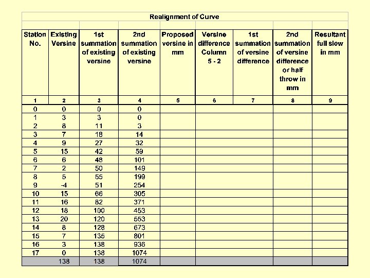
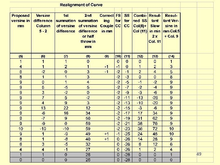
PRINCIPLES APPLIED IN ROC • Existing versines are available from measurements and the solution has to be ‘proposed’ • Take the difference between the existing and proposed versines and then work out first and second summation – The second summation of versine difference at the first and the last station should be zero. [Slew at the first and last stations shall be zero] – The first summation of versine difference shall be zero at last station • ROC AS DONE IN FIELD IS ALSO CALLED “STRING LINING OPERATIONS” 32
STEPS IN STRING LINING OPERATION • Survey existing versines • Find sum of existing versines and get an idea of the average versines • Propose new versines for the curve according to the principles : – Sum of existing versines = Sum of proposed versines – Uniform rate of change of versine in transition portion – Uniform versine over circular portion 33
STRING LINING METHOD-OPERATIONS • Workout Versine Difference (vp-ve) • Workout First Summation of Versine Difference – FS at last station shall be zero • Workout Second Summation of Versine Difference – Value at first and last station shall be zero 34
35
36
37
38
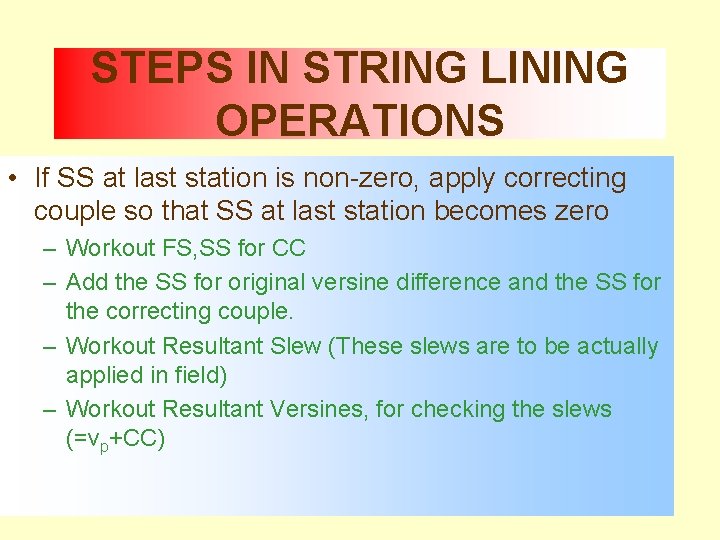
STEPS IN STRING LINING OPERATIONS • If SS at last station is non-zero, apply correcting couple so that SS at last station becomes zero – Workout FS, SS for CC – Add the SS for original versine difference and the SS for the correcting couple. – Workout Resultant Slew (These slews are to be actually applied in field) – Workout Resultant Versines, for checking the slews (=vp+CC) 39
Correcting 40
Correcting 42
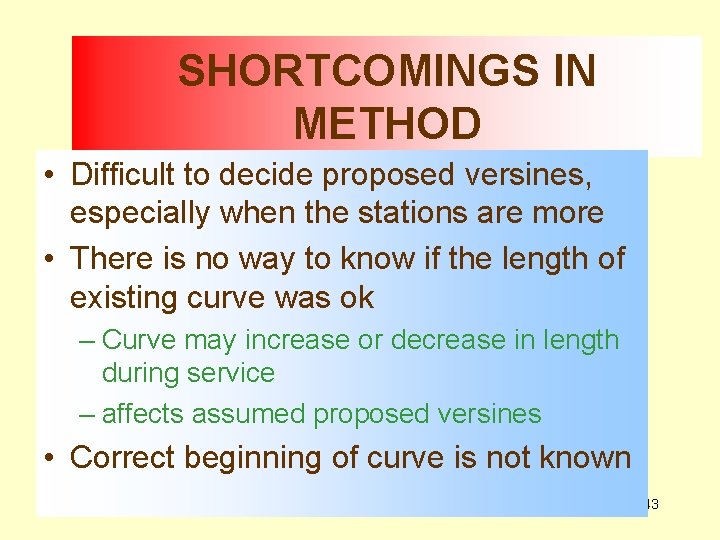
SHORTCOMINGS IN METHOD • Difficult to decide proposed versines, especially when the stations are more • There is no way to know if the length of existing curve was ok – Curve may increase or decrease in length during service – affects assumed proposed versines • Correct beginning of curve is not known 43
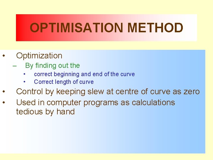
OPTIMISATION METHOD • Optimization – By finding out the • • correct beginning and end of the curve Correct length of curve Control by keeping slew at centre of curve as zero Used in computer programs as calculations tedious by hand 44
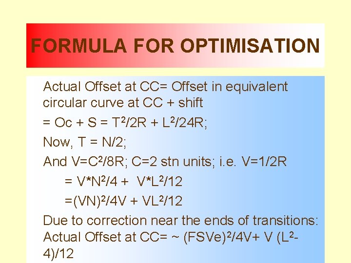
FORMULA FOR OPTIMISATION Actual Offset at CC= Offset in equivalent circular curve at CC + shift = Oc + S = T 2/2 R + L 2/24 R; Now, T = N/2; And V=C 2/8 R; C=2 stn units; i. e. V=1/2 R = V*N 2/4 + V*L 2/12 =(VN)2/4 V + VL 2/12 Due to correction near the ends of transitions: Actual Offset at CC= ~ (FSVe)2/4 V+ V (L 2 - 45 4)/12
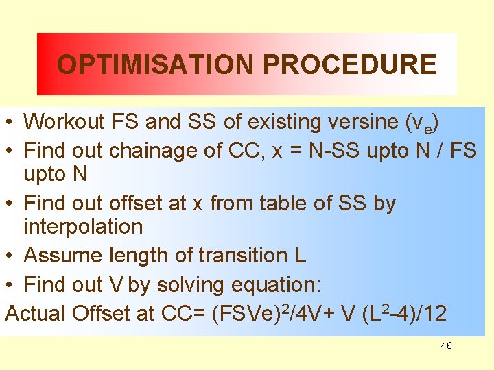
OPTIMISATION PROCEDURE • Workout FS and SS of existing versine (ve) • Find out chainage of CC, x = N-SS upto N / FS upto N • Find out offset at x from table of SS by interpolation • Assume length of transition L • Find out V by solving equation: Actual Offset at CC= (FSVe)2/4 V+ V (L 2 -4)/12 46
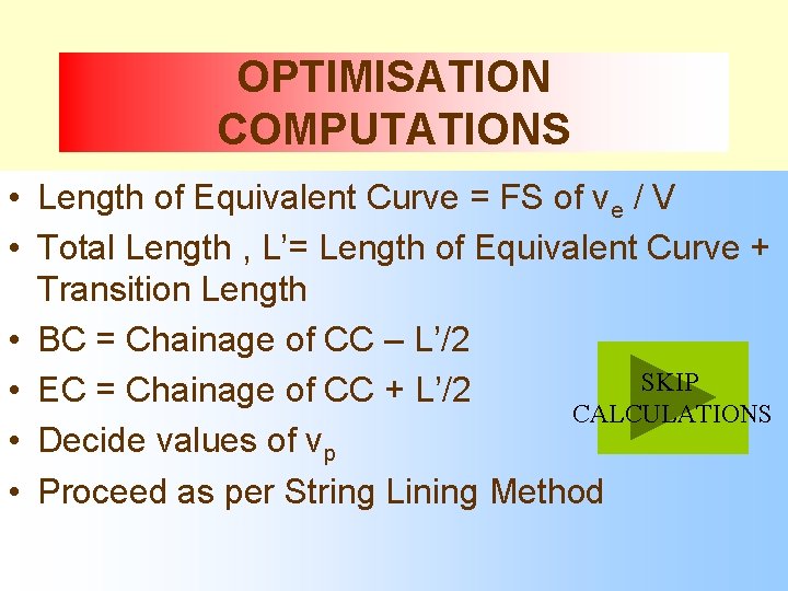
OPTIMISATION COMPUTATIONS • Length of Equivalent Curve = FS of ve / V • Total Length , L’= Length of Equivalent Curve + Transition Length • BC = Chainage of CC – L’/2 SKIP • EC = Chainage of CC + L’/2 CALCULATIONS • Decide values of vp • Proceed as per String Lining Method 47
48
49
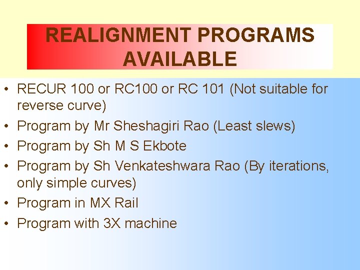
REALIGNMENT PROGRAMS AVAILABLE • RECUR 100 or RC 101 (Not suitable for reverse curve) • Program by Mr Sheshagiri Rao (Least slews) • Program by Sh M S Ekbote • Program by Sh Venkateshwara Rao (By iterations, only simple curves) • Program in MX Rail • Program with 3 X machine 51
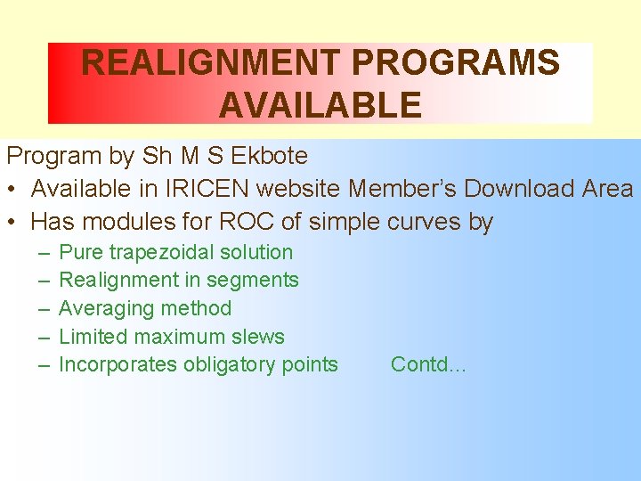
REALIGNMENT PROGRAMS AVAILABLE Program by Sh M S Ekbote • Available in IRICEN website Member’s Download Area • Has modules for ROC of simple curves by – – – Pure trapezoidal solution Realignment in segments Averaging method Limited maximum slews Incorporates obligatory points Contd… 52
REALIGNMENT PROGRAMS AVAILABLE Program by Sh M S Ekbote • Has modules for ROC of – Reverse curves – Only transitions – Vertical curves • Algorithm based on equating the maximum inward and outward slews (Shifts the curve inwards or outwards to equalize the maximum values of slews) 53
THANK YOU 54