Reaction Forces and Moments Free Body Diagram Reactions

Reaction Forces and Moments

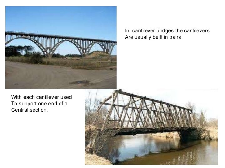
Free Body Diagram Reactions Different types of support reactions • Cable, rope, or chain • Pin • Roller • Built-in end – Cantilever

Cable Support Examples Cable Chain Rope

Pin Supports

Roller Support
 and")
Pin Support • Pin – Replaced with TWO reaction forces, one vertical (y) and one horizontal (x). A A RAx RAy

Roller Support • Roller – Replaced with ONE reaction force, perpendicular to surface A A RAy

Common Support Reactions • Beams and truss bridges are usually supported with one pin support and one roller support. This is called a simply supported object. FBD for the simply supported beam. A B RAx RAy RBy

Truss Bridge • Supported with a pin at one end a roller at the other Draw the FBD of the entire truss bridge. D E B C A 500 lb

Truss Bridge FBD • FBD of the entire truss bridge D E B RAx C RAy RCy 500 lbf

Moment The moment of a force is a measure of the tendency of the force to rotate the body upon which it acts.

Terminology =F lever arm pivot distance =D The distance must be perpendicular to the force.

Moments Formula =F pivot distance =D Moment M=Fx. D
 Foot (ft) lb-ft")
Units for Moments Force Distance Moment English Customary Pound force (lbf) Foot (ft) lb-ft SI Newton (N) Meter (m) N-m

Rotation Direction In order to add moments, it is important to know if the direction is clockwise (CW) or counterclockwise (CCW). CCW is positive CW is negative
 ¯ D")
Moment Calculations Wrench F = 20. lb M = -(F x D) ¯ D = 9. 0 in. =. 75 ft M = -(20. lb x. 75 ft) M = -15 lb-ft D = 9. 0 in. (15 lb-ft clockwise)
 ¯")
Moment Calculations Longer Wrench F = 20. lb M = -(F x D) ¯ M = -(20. lb x 1. 0 ft) M = -20. lb-ft D = 1. 0 ft

Moment Calculations L - Shaped Wrench F = 20. lb D = 3 in. =. 25 ft 3 in. M = -(F x D) M = -(20. lb x. 25 ft) ¯ M = -5 lb-ft D = 1. 0 ft

Moment Calculations Z - Shaped Wrench F = 20. lb 9 in. D = 8 in. + 10 in. = 1. 5 ft M = -(F x D) M = -(20. lb x 1. 5 ft) ¯ M = -30. lb-ft 8 in. 10. in.

Moment Calculations Wheel and Axle D = r = 50. cm = 0. 50 m r = 50. cm M=Fx. D M = 100 N x 0. 50 m M = 50 N-m + F = 100 N

Determining Equilibrium The sum of all moments about any point or axis is zero. ΣM = 0 M 1 + M 2 + M 3. . . = 0

Moment Calculations See-Saw

Moment Calculations ΣM = 0 See-Saw M 1 = M 2 F 1 x D 1 = F 2 x D 2 25 lb x 4. 0 ft = - 40. lb x D 2 F 2 = 40. lb 100 lb-ft = - 40. lb x D 2 - 40. lb 2. 5 ft = D 2 F 1 = 25 lb + D 1 = 4. 0 ft D 2 = ? ft

Moment Calculations Loaded Beam Select A as the pivot location. Solve for RBy ΣM = 0 MB = M C RBy x DAB = FC x DAC DAB = 10. 00 ft DAC= 3. 00 ft RBy x 10. 00 ft = 35. 0 lb x 3. 00 ft RBy x 10. 00 ft = 105 lb-ft 10. 00 ft C A B RBy = 10. 5 lb RAy + RBy = 35. 0 lb RAy = 35. 0 lb – 10. 5 lb = 24. 5 lb FC = 35. 0 lb RAy RBy
- Slides: 25