
Rayat Shikshan Sansthas S M Joshi College Hadapsar028
- Slides: 16
Rayat Shikshan Sanstha’s S. M. Joshi College Hadapsar-028 Department of Electronics Science Amplifier Presented by. Dr. Bhalerao S. P
Practical Amplifier n To analyse the circuit: n n n Determine quiescent conditions Calculate mutual conductance Calculate small signal performance n n Voltage Gain Input Impedance Output Impedance Cut-off frequency
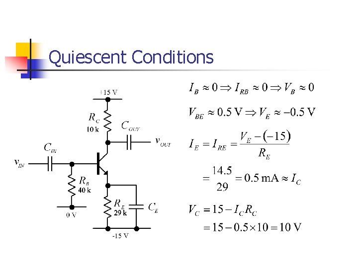
Quiescent Conditions
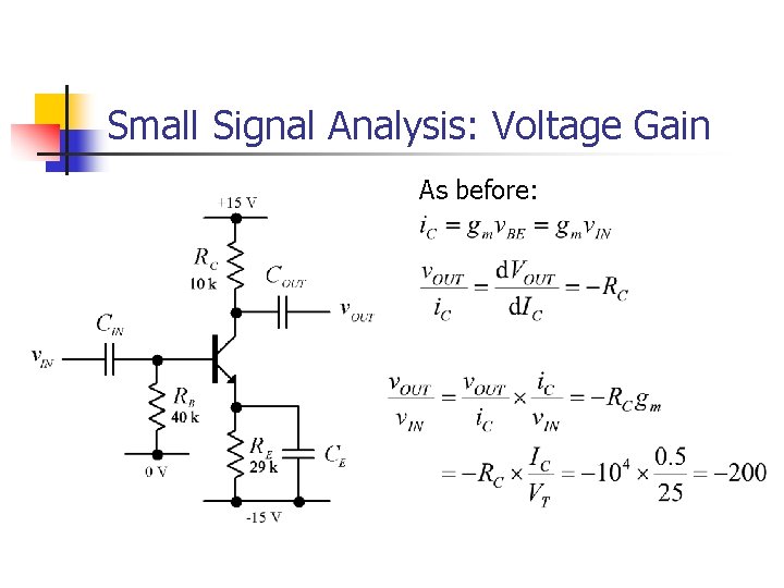
Small Signal Analysis: Voltage Gain As before:
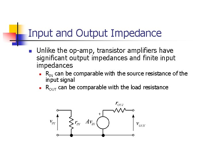
Input and Output Impedance n Unlike the op-amp, transistor amplifiers have significant output impedances and finite input impedances n n RIN can be comparable with the source resistance of the input signal ROUT can be comparable with the load resistance
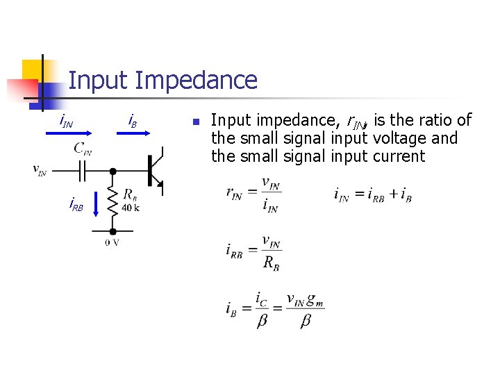
Input Impedance i. IN i. RB i. B n Input impedance, r. IN, is the ratio of the small signal input voltage and the small signal input current
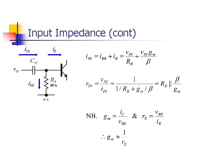
Input Impedance (cont) i. IN i. RB i. B
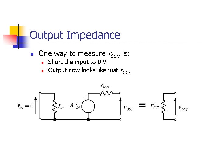
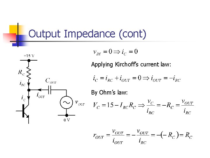
Output Impedance n One way to measure r. OUT is: n n Short the input to 0 V Output now looks like just r. OUT
Output Impedance (cont) Applying Kirchoff’s current law: By Ohm’s law:
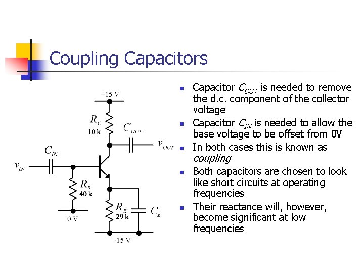
Coupling Capacitors n n n Capacitor COUT is needed to remove the d. c. component of the collector voltage Capacitor CIN is needed to allow the base voltage to be offset from 0 V In both cases this is known as coupling Both capacitors are chosen to look like short circuits at operating frequencies Their reactance will, however, become significant at low frequencies
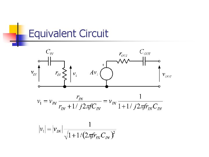
Equivalent Circuit
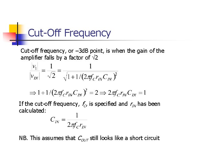
Cut-Off Frequency Cut-off frequency, or – 3 d. B point, is when the gain of the amplifier falls by a factor of Ö 2 If the cut-off frequency, f. C, is specified and r. IN has been calculated: NB. This assumes that COUT still looks like a short circuit
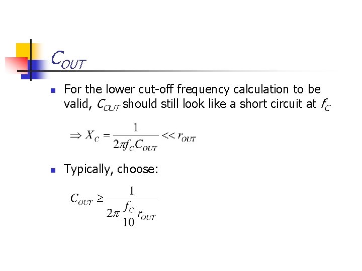
COUT n n For the lower cut-off frequency calculation to be valid, COUT should still look like a short circuit at f. C Typically, choose:
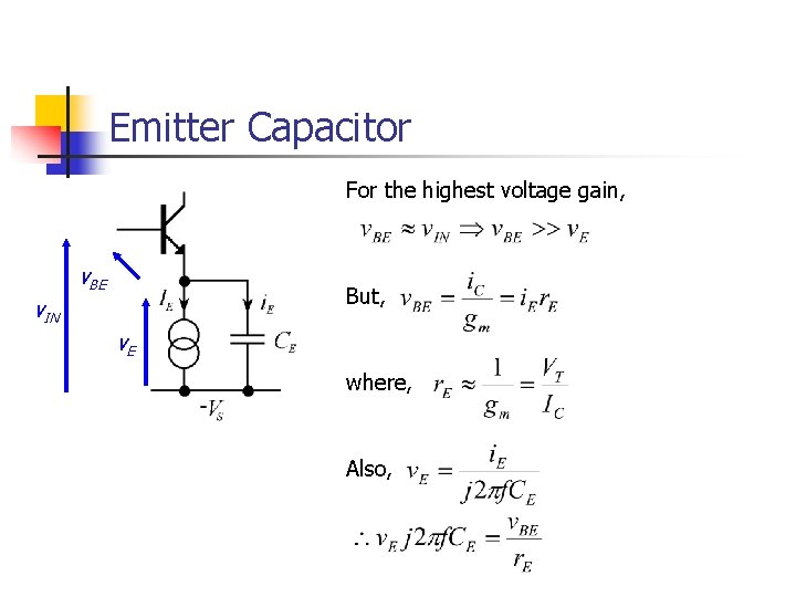
Emitter Capacitor For the highest voltage gain, v. BE But, v. IN v. E where, Also,
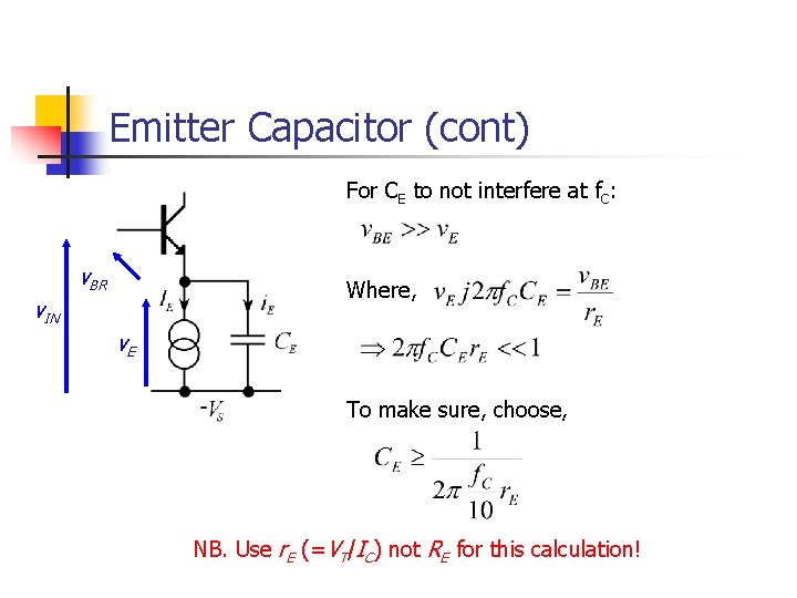
Emitter Capacitor (cont) For CE to not interfere at f. C: v. BR Where, v. IN v. E To make sure, choose, NB. Use r. E (=VT/IC) not RE for this calculation!
Summary n In the context of the common-emitter amplifier we have covered: n n n Small signal analysis Mutual conductance Input/output impedance Coupling capacitor requirements and cut-off frequencies Next time: n n n Applying the same principles to the differential amplifier It’s actually a much easier circuit to analyse – honest! Make sure you’re happy with the fundamentals by then!