Ray tracing in computer graphics Ray tracing Figure


")

 does ray intersect")


 { if (n>N) return ray. Efield;")


")


- Slides: 36
Ray tracing in computer graphics
Ray tracing Figure 3. Tracing rays from the light source to the eye. Lots of rays are wasted because they never reach the eye. Figure 4. We trace a new ray from each ray-object intersection directly towards the light source
Reflection and refraction Figure 6. Recursive reflection and refraction
Ray tracing in computer graphics
Scattering from a patch : Green’s theorem where
Physical optics approximation where Incident wave where reflect wave
Scattered wave from a patch Receiver position Source position Equi-phase plane
Radiation pattern vs. patch size
The Basic Idea • Simulate light rays from light source to eye Light Eye R t eflec Incid ay r d e ent r Surface ay
“Forward” Ray-Tracing • Trace rays from light • Lots of work for little return Light Image Plane Light Rays Eye Object
“Backward” Ray-Tracing • Trace rays from eye instead • Do work where it matters Light Image Plane Eye Object This is what most people mean by “ray tracing”.
Backward ray tracing
Generating Rays • Trace a ray for each pixel in the image plane tan(fovx) * 2 Image Plane fovx Eye (Looking down from the top)
Generating Rays n Trace a ray for each pixel in the image plane (Looking from the side) m (tan(fovx)* 2) / m Eye n Image Plane (tan(fovy)* 2) / n
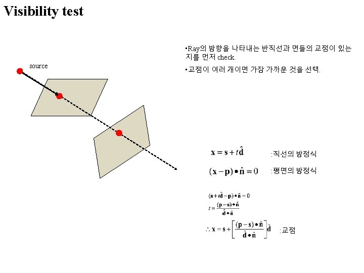
Triangle Intersection n n Want to know: at what point (p) does ray intersect triangle? Compute lighting, reflected rays, shadowing from that point x ? ? ?
Triangle Intersection • Step 1 : Intersect with plane Plane normal n = <A, B, C> p rd ro p = -(n. ro + D) / (n. rd )
Triangle Intersection n Step 2 : Check against triangle edges n V 1 V 0 V 1 E 0 p V 0 Ei = Vi. Vi+1 x n (plane A, B, C) di = -A. N (plane D) V 2 Plug p into (p. Ei + di ) for each edge if signs are all positive or negative, point is inside triangle!
Generating Rays n Trace a ray for each pixel in the image plane render. Image(){ for each pixel i, j in the image ray. set. Start(0, 0, 0); // ro ray. set. Dir ((. 5 + i) * tan(fovx)* 2 / m, (. 5 + j) * tan(fovy)* 2 / n, 1. 0); // rd ray. normalize(); image[i][j] = ray. Trace(ray); }
Ray tracer • Recursive ray evaluation ray. Trace(ray) { if (n>N) return ray. Efield; obj = hit. Object(ray, p, n, triangle); if (!obj)return black; if(obj->material==reflective) { ray. reflect(); n++; ray. Trace(ray); } if (obj->material==transmissive) { ray. transmit(); n++; ray. Trace(ray); } }
Acceleration • 1280 x 1024 image with 10 rays/pixel • 1000 objects (triangle, CSG, NURBS) • 3 levels recursion 39321600000 intersection tests 100000 tests/second -> 109 days! Must use an acceleration method!
Bounding volumes • Use simple shape for quick test, keep a hierarchy
Space Subdivision • Break your space into pieces • Search the structure linearly
Reciprocity Transmitting mode Receiving mode 수신 안테나 송신 안테나 수신 안테나
Projection screen
Calculation of E-field 투과 및 반사계수 (dyadic)
Fields and power radiated by an antenna In the far field, : Poynting vector (power density) If the transmitted power is PT,
Antenna pattern characteristics E-plane, H-plane
Directivity : D
Antenna gain and efficiency : Gain takes into account losses and reflections of the antenna. Antenna gain and effective area Received power : Radiation power density by a transmitting antenna
Radar cross section 31 Pt : 송신 전력 Transmit Receive : Power received by an obstacle with cross section σ : Reradiated power density by the obstacle : Received power due to scattering
Return signal modeling by RCS 32
RCS 측정 setup 33
RCS 측정 34 Maximum 29 m
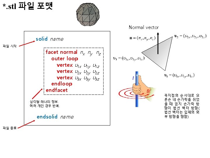
solid plainland 2 facet normal 1 0 0 outer loop vertex 1000 -1000 1. 2079227 e-013 vertex 1000 -994. 57647 52. 531029 vertex 1000 -1000 52. 507892 endloop endfacet normal 1 0 0 outer loop vertex 1000 -1000 1. 2079227 e-013 vertex 1000 -981. 6656 52. 63194 vertex 1000 -994. 57647 52. 531029 endloop endfacet normal 1 0 0 outer loop vertex 1000 -940. 34082 52. 733927 vertex 1000 -981. 6656 52. 63194 vertex 1000 -1000 1. 2079227 e-013 endloop endfacet. . . facet normal 0. 0026392427 -0. 0042659265 0. 99998742 outer loop vertex 987. 08919 -981. 6656 52. 620182 vertex 987. 08919 -1000 52. 541967 vertex 1000 -994. 57647 52. 531029 endloop endfacet endsolid plainland 2