
RAIL STRESS By Anil Choudhary Sr ProfIRICEN INTRODUCTION
RAIL STRESS By Anil Choudhary Sr Prof/IRICEN
INTRODUCTION § Axle loads are gradually increasing on IR. § Max 20. 32 T (CC) till 2006. § Increased to 22. 32 t (CC+6+2) in 2006 and subsequently to 22. 82 & 22. 9 t (CC+8+2)in 2007 at 75 kmph. § 25 t axle load operation started in 2010 at 50 kmph. § DFC is being designed for 32. 5 t axle load, though initially freight will run at 25 t axle load.
INTRODUCTION § These operations shall be on the same track having/planned for semi high speed passenger operation (Mixed Traffic). § Speed of freight operation is now proposed to be increased to 100 kmph. § Further, some of the routes are being planned for upgradation to 200 kmph passenger operations
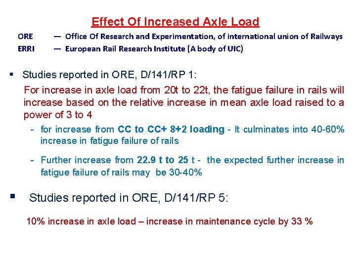
Effect Of Increased Axle Load ORE ERRI — Office Of Research and Experimentation, of international union of Railways — European Rail Research Institute (A body of UIC) § Studies reported in ORE, D/141/RP 1: For increase in axle load from 20 t to 22 t, the fatigue failure in rails will increase based on the relative increase in mean axle load raised to a power of 3 to 4 - for increase from CC to CC+ 8+2 loading - It culminates into 40 -60% increase in fatigue failure of rails - Further increase from 22. 9 t to 25 t - the expected further increase in fatigue failure of rails may be 30 -40% § Studies reported in ORE, D/141/RP 5: 10% increase in axle load – increase in maintenance cycle by 33 %
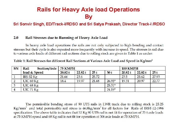
Rails for Heavy Axle load Operations By Sri Sonvir Singh, ED/Track-I/RDSO and Sri Satya Prakash, Director Track-I /RDSO
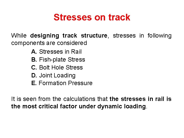
Stresses on track While designing track structure, stresses in following components are considered A. Stresses in Rail B. Fish-plate Stress C. Bolt Hole Stress D. Joint Loading E. Formation Pressure It is seen from the calculations that the stresses in rail is the most critical factor under dynamic loading.
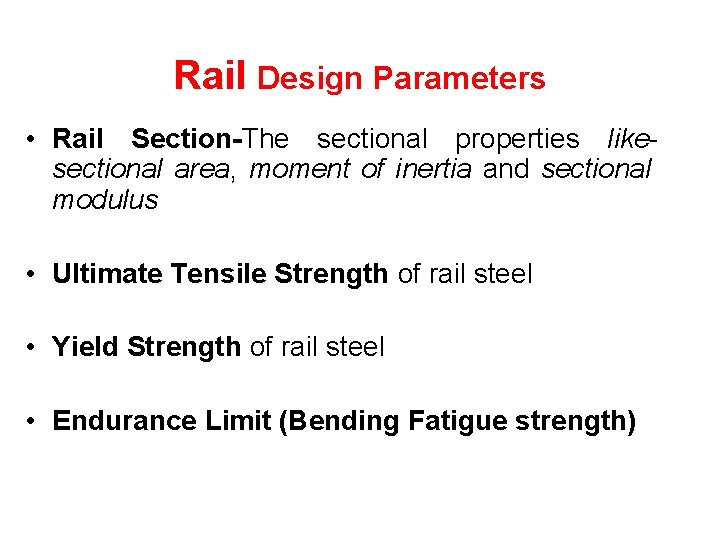
Rail Design Parameters • Rail Section-The sectional properties likesectional area, moment of inertia and sectional modulus • Ultimate Tensile Strength of rail steel • Yield Strength of rail steel • Endurance Limit (Bending Fatigue strength)
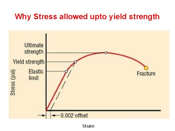
Why Stress allowed upto yield strength Strain
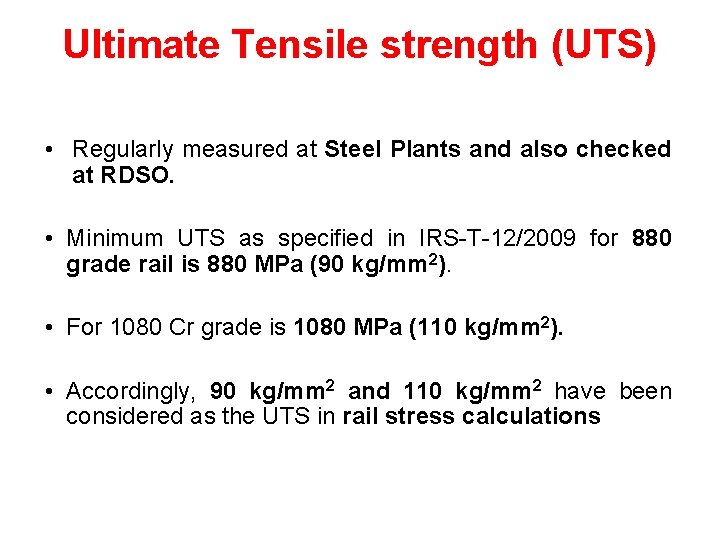
Ultimate Tensile strength (UTS) • Regularly measured at Steel Plants and also checked at RDSO. • Minimum UTS as specified in IRS-T-12/2009 for 880 grade rail is 880 MPa (90 kg/mm 2). • For 1080 Cr grade is 1080 MPa (110 kg/mm 2). • Accordingly, 90 kg/mm 2 and 110 kg/mm 2 have been considered as the UTS in rail stress calculations
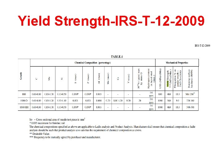
Yield Strength-IRS-T-12 -2009
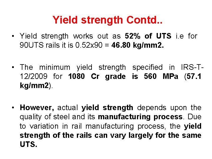
Yield strength Contd. . • Yield strength works out as 52% of UTS i. e for 90 UTS rails it is 0. 52 x 90 = 46. 80 kg/mm 2. • The minimum yield strength specified in IRS-T 12/2009 for 1080 Cr grade is 560 MPa (57. 1 kg/mm 2). • However, actual yield strength depends upon the quality of steel and its manufacturing process. Due to variation in rail manufacturing process, the yield strength of the rails can vary largely for the same UTS.
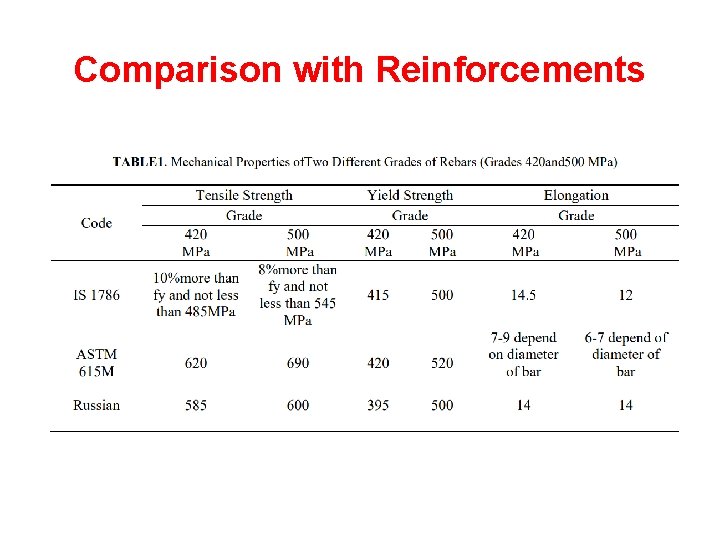
Comparison with Reinforcements
Endurance Limit • Endurance Limit (Bending Fatigue Strength): Endurance strength is defined as the maximum value of completely reversed bending stress that a material can withstand for a finite number of cycles without a fatigue failure. In the tests carried out by RDCIS, the endurance limit of 90 UTS rail has been found as 333 MPa.
Stresses in Rail Different stresses to which Rails are subjected 1. Internal Residual Stress 2. Thermal Stresses due to temperature variation 3. Bending Stresses and Torsional stress (Due Load and its dynamic impact). 4. Stresses due to Miscellaneous factors. 5. Rail Wheel Contact Stresses 1 to 4 are called bulk stresses and are used for Rail design on yield strength criteria. Contact stresses are responsible Rolling Contact Fatigue (RCF) and rail to have sufficient shear strength to bear this stress. This is to be controlled during maintenance. (Other properties like fracture toughness and fatigue crack growth rate also influence the performance of rail)
Failure Criteria to be checked for Rail Design Following three failure criteria are normally adopted in deciding a suitable rail section (i) Yielding under combination of Bulk stresses (ii)Contact stress failure/fatigue or failure in shear (iii)Fatigue due to bending stress under cyclic loading
Rail suitability for Bulk stress– Assessment Methodology • Calculation of induced bulk stress due to v Internal residual stress during manufacturing v Thermal variation v Other unforeseen factors. v Bending stress due to Rolling stock i. e. its load and dynamic impact The sum of induced stress at any location in rail section should not exceed the yield strength of rail steel.
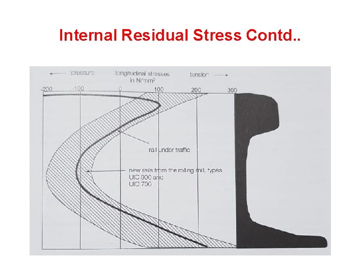
Bulk Stresses 1 -Internal Residual Stresses Residual stresses come during the rail manufacturing process mainly on account of difference in time of phase transformations in railhead, web and foot during rail cooling & on straightening method followed.
Internal Residual Stresses Contd… Ø Welding of rail also creates residual stresses, the distribution of which is very complex with respect to magnitude and direction. Ø For rail stress calculation purpose, we only consider the residual stress in rail developed during manufacturing process. Ø These stresses are measured in lab (BSP) by taking a slice of rail as per procedure adopted by UIC.
Internal Residual Stress Contd. .
Internal Residual Stresses Contd… For calculation purpose we have been taking this value as 6 kg/mm 2 (After 1986) It was always deducted
Internal Residual Stresses Contd… • The internationally accepted value for 90 UTS rail is 250 MPa which should not be exceeded. • The rails produced in India by SAIL comply to these standards as indicated by the data reported in October 2017 by RDCIS, Ranchi. • Accordingly, residual stress considered in the rail stress calculation is 240 MPa (24. 5 kg/mm 2) at rail foot center and as 6 kg/mm 2 at the edge of rail foot (The stress at rail foot centre is tension making the calculation unsafe against fracture)
Bulk Stress 2. Thermal Stresses Ø Thermal stresses are created due to restraining of expansion or contraction of rail (LWR). Ø These are on account of variation in prevailing temperature with respect to installation temperature (td) on account of fixity at sleeper seat and resistance offered due to ballast in case of welded track. Ø For LWR track, these have been worked out for zone IV (maximum variation of temp in this zone).
Thermal Stresses Contd. . ØAs per revised provisions of the LWR Manual, Distressing temperature (td) for 52 kg and 60 kg rails from tm+5 to tm+10 (Earlier-tm to tm+5 ) ØFor calculation td is taken as tm+7. 5 (Earlier it was tm+5) Øtm is 38 degree C Øtd– 45. 5 Degree C (Earlier 43 Degree C) ØThermal stresses ( E α dt)= 11. 32 kg/mm 2 (Earlier 10. 75 Kg/mm 2 )
Bulk Stress 3. Stresses due to unforeseen reasons Ø As per an estimate made at RDSO in 2006, stresses in the bottom flange of rails on account of flexed laying on a 4 -degree curve for 52 kg and 60 kg rails are 5. 88 kg/mm 2 and 6. 22 kg/mm 2 respectively. Ø One side solar radiation- The difference in the temperature on sunny non-windy side and shadowwindy side can be as high as 7 -degree C.
Stresses due to unforeseen reasons Present status: Ø A nominal value as 10 % of Yield Strength (4. 68 Kg/mm 2 for 90 UTS) at the edges of rail foot and head and equal to 10% of calculated bending stress at foot center has been considered for unforeseen stresses. (Earlier 10% of yield strength every where)
Bulk Stress 4. Bending Stresses Bending stresses are induced stresses on account of movement of rolling stock. Ø These depend on many factors such as: § Track Modulus. § Wheel Load. § Dynamic Augment. § Rail Section Properties.
Bending Stresses Contd. . Ø Current practices across railway systems for the calculation of rail bending moment and vertical deflection and consequently the bending stresses are mainly based on the “Beam on elastic foundation model (Winkler initially for longitudinal track / Zimmermann Model for track with cross sleepers) • Methodology followed in IR by RDSO is as given in Technical Monograph No. 12 1959 Track Loading Fundamentals (C. W Clark)
Bending Stresses Contd. . The basic assumptions on elastic foundation model theory are • The several components of track are one complete unit. • The rails are continuously supported on sleepers which are considered to be elastic. • The ballast and formation are also considered elastic.
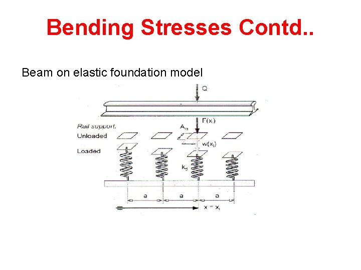
Bending Stresses Contd. . Beam on elastic foundation model
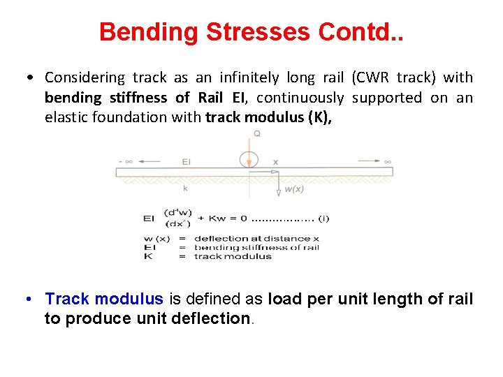
Bending Stresses Contd. . • Considering track as an infinitely long rail (CWR track) with bending stiffness of Rail EI, continuously supported on an elastic foundation with track modulus (K), • Track modulus is defined as load per unit length of rail to produce unit deflection.
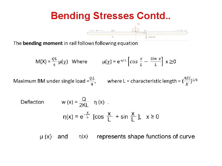
Bending Stresses Contd. . •
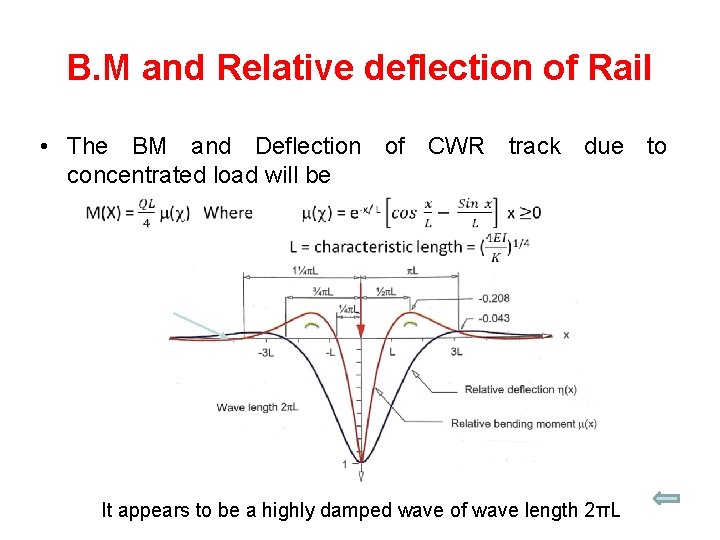
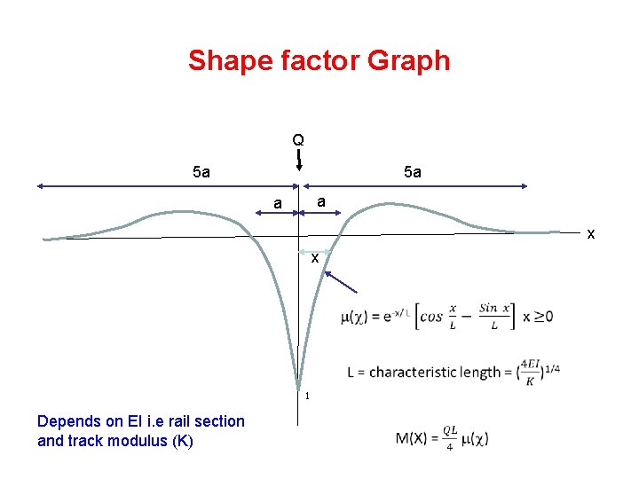
B. M and Relative deflection of Rail • The BM and Deflection of CWR track due to concentrated load will be � � It appears to be a highly damped wave of wave length 2πL
Shape factor Graph Q 5 a 5 a a a x x � � 1 Depends on EI i. e rail section and track modulus (K) �
Effect of multiple wheels Q’= Maximum BM = Q’L/4
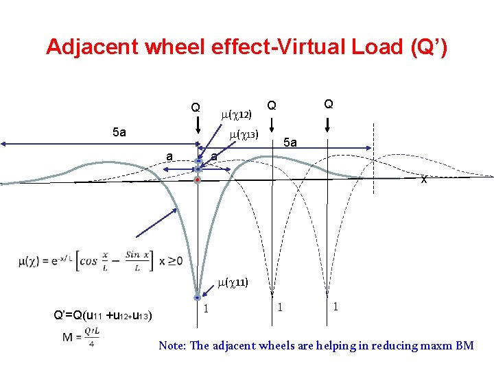
Adjacent wheel effect-Virtual Load (Q’) Q ( 12) 5 a ( 13) a Q Q 5 a a x � ( 11) Q’=Q(u 11 +u 12+u 13) � 1 1 1 Note: The adjacent wheels are helping in reducing maxm BM
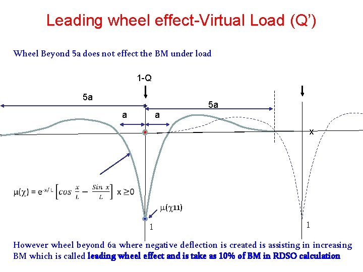
Leading wheel effect-Virtual Load (Q’) Wheel Beyond 5 a does not effect the BM under load 1 -Q 5 a 5 a a a x � ( 11) 1 1 However wheel beyond 6 a where negative deflection is created is assisting in increasing BM which is called leading wheel effect and is take as 10% of BM in RDSO calculation
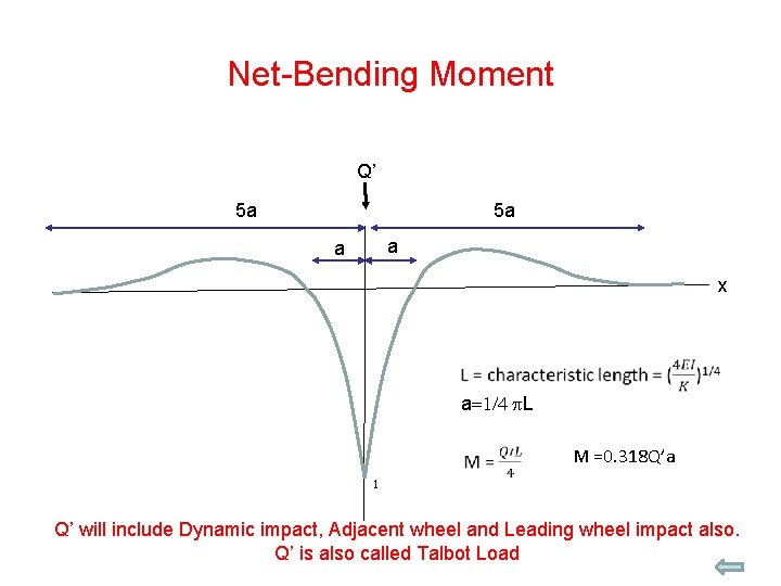
Net-Bending Moment Q’ 5 a 5 a a a x � a=1/4 p. L � M =0. 318 Q’a 1 Q’ will include Dynamic impact, Adjacent wheel and Leading wheel impact also. Q’ is also called Talbot Load
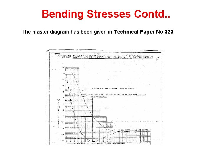
Bending Stresses Contd. . The master diagram has been given in Technical Paper No 323
Bending Stresses Contd. . Dynamic Augmentation, also known as Speed Factor or Impact factor Ø On IR, actual dynamic augment at the rail level for present day rolling stock is not known since it has never been measured for want of measuring wheel. Ø For BG vehicles, the graphs plotted in RDSO’s report C -100 are being used. (The factor is 1. 72 for 100 kmph speed for freight stocks) Ø Where the measured values of dynamic augment are not available, the dynamic augment values for similar vehicles are to be adopted.
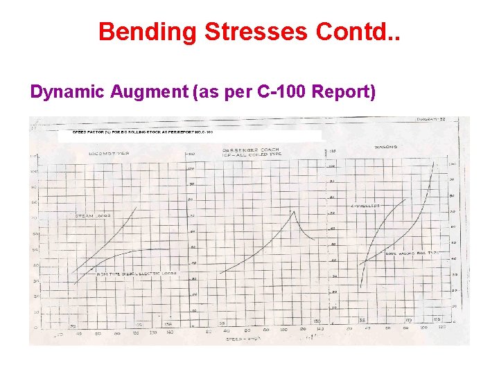
Bending Stresses Contd. . Dynamic Augment (as per C-100 Report)
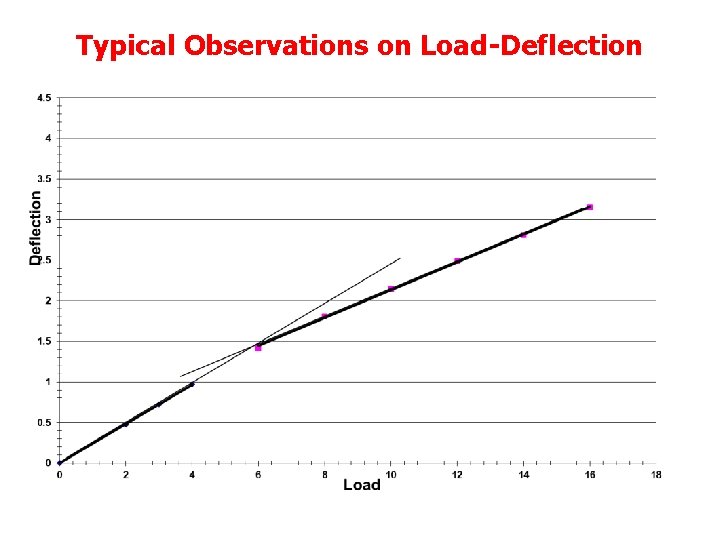
Bending Stresses Contd. . Track Modulus Ø Initial load of 4 t is considered for initial track modulus and beyond the load of 4 t, the track modulus is considered as elastic track modulus.
Typical Observations on Load-Deflection
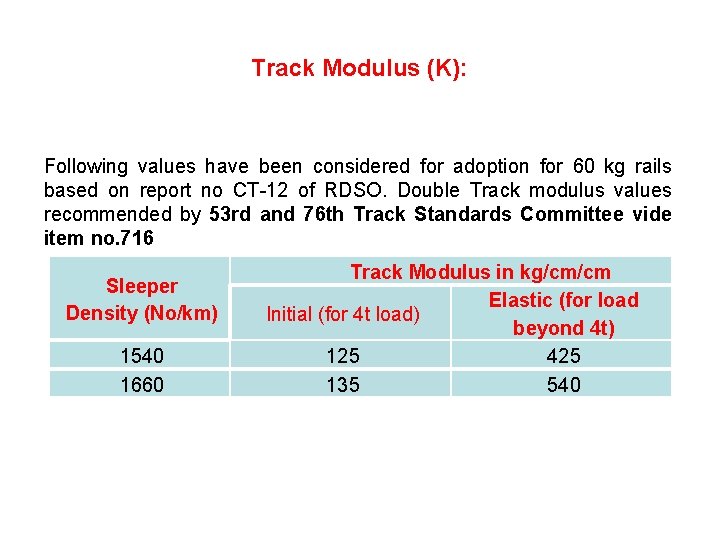
Track Modulus (K): Following values have been considered for adoption for 60 kg rails based on report no CT-12 of RDSO. Double Track modulus values recommended by 53 rd and 76 th Track Standards Committee vide item no. 716 Sleeper Density (No/km) 1540 1660 Track Modulus in kg/cm/cm Elastic (for load Initial (for 4 t load) beyond 4 t) 125 425 135 540
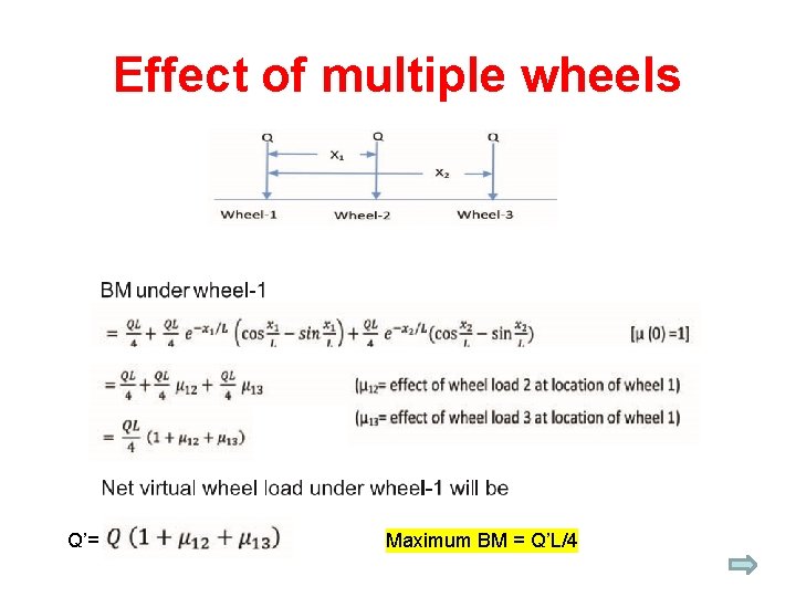
Bending Stresses Contd. . Vertical Load acting Ø An eccentricity of 15 mm for vertical load is adopted for calculations. Ø The virtual wheel used in calculation of rail stress is worked out by modifying the static wheel load with following factors • Dynamic augment • Adjacent wheel effect • Leading wheel effect
Bending Stresses Contd. . Lateral Flange Force acting Ø The maximum lateral flange force per axle is taken as per Prud’ Homme’s Limit Equation: Lateral Force = α (10+P 0/3) where P 0 is axle load and α is taken as 0. 85 for all rolling stocks. (One assumption is that this load is equally distributed on both rail) Ø In case actual measured Lateral forces are available for the stock under consideration, the same are taken in calculating stresses. (This can be done by measuring wheel)
Bending Stresses Contd. . Following loading conditions are considered for calculating the longitudinal Bending Stresses in rail: v Stress due to vertical load. v Stress due to torsion caused by eccentricity of vertical load. v Stress due to torsion caused by lateral load. v Stress due to lateral deflection caused by lateral load. Analysis done by S. Timoshinko and B. Langer
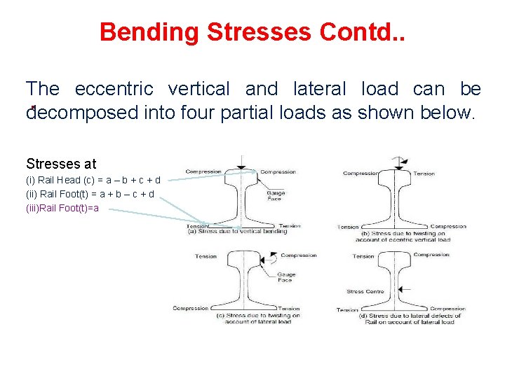
Bending Stresses Contd. . The eccentric vertical and lateral load can be. decomposed into four partial loads as shown below. Stresses at (i) Rail Head (c) = a – b + c + d (ii) Rail Foot(t) = a + b – c + d (iii)Rail Foot(t)=a
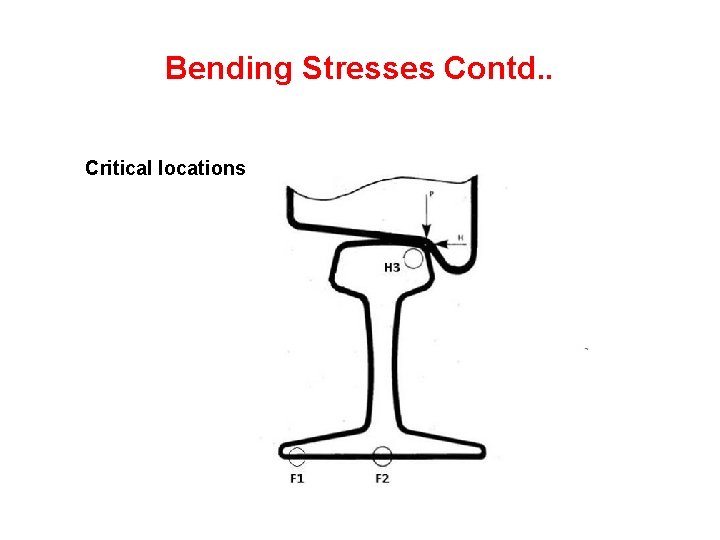
Bending Stresses Contd. . Critical locations
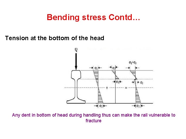
Bending stress Contd… Tension at the bottom of the head Any dent in bottom of head during handling thus can make the rail vulnerable to fracture
Bending Stresses Contd. . Rail section taken for all calculation purpose Ø For working out rail stresses, the properties like moment of inertia and section modulus of rails are being assumed 10% lesser than the properties for new rails. Ø The wear is assumed to be 5%. (Renewal criteria is 7% )
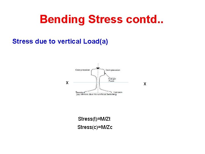
Bending Stress contd. . Stress due to vertical Load(a) x x Stress(t)=M/Zt Stress(c)=M/Zc
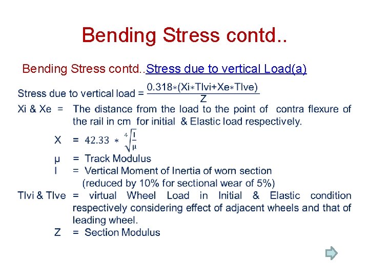
Bending Stress contd. . Stress due to vertical Load(a) �
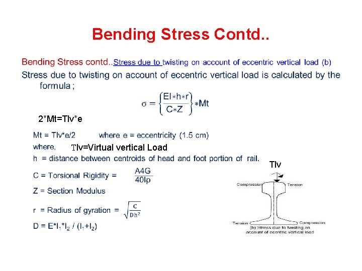
Bending Stress Contd. . 2*Mt=Tlv*e Tlv=Virtual vertical Load Tlv
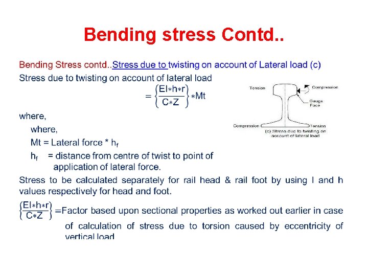
Bending stress Contd. . •
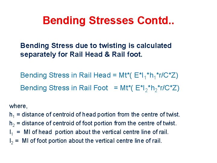
Bending Stresses Contd. . Bending Stress due to twisting is calculated separately for Rail Head & Rail foot. Bending Stress in Rail Head = Mt*( E*I 1*h 1*r/C*Z) Bending Stress in Rail Foot = Mt*( E*I 2*h 2*r/C*Z) where, h 1 = distance of centroid of head portion from the centre of twist. h 2 = distance of centroid of foot portion from the centre of twist. I 1 = MI of head portion about the vertical centre line of rail. I 2 = MI of foot portion about the vertical centre line of rail.
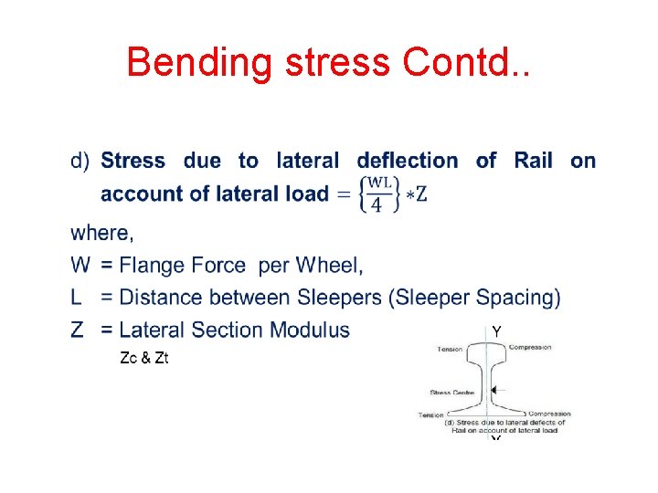
Bending stress Contd. .
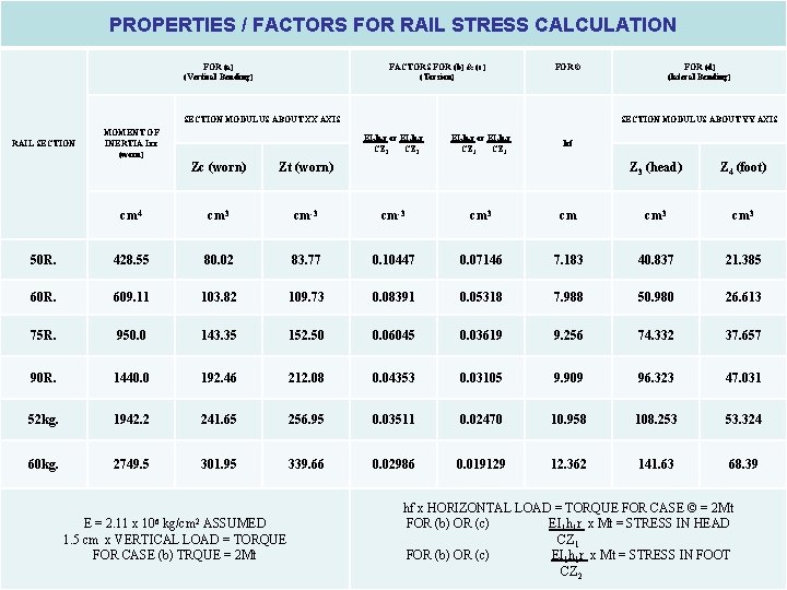
PROPERTIES / FACTORS FOR RAIL STRESS CALCULATION FOR (a) (Vertical Bending) FACTORS FOR (b) & (c) (Torsion) FOR © SECTION MODULUS ABOUT XX AXIS RAIL SECTION MOMENT OF INERTIA Ixx (worn) FOR (d) (lateral Bending) SECTION MODULUS ABOUT YY AXIS EI 1 h 1 r or EI 2 h 2 r CZ 1 EI 1 h 1 r or EI 2 h 2 r CZ 2 Zc (worn) Zt (worn) cm 4 cm 3 cm-3 cm 3 50 R. 428. 55 80. 02 83. 77 0. 10447 60 R. 609. 11 103. 82 109. 73 75 R. 950. 0 143. 35 90 R. 1440. 0 52 kg. 60 kg. hf Z 3 (head) Z 4 (foot) cm cm 3 0. 07146 7. 183 40. 837 21. 385 0. 08391 0. 05318 7. 988 50. 980 26. 613 152. 50 0. 06045 0. 03619 9. 256 74. 332 37. 657 192. 46 212. 08 0. 04353 0. 03105 9. 909 96. 323 47. 031 1942. 2 241. 65 256. 95 0. 03511 0. 02470 10. 958 108. 253 53. 324 2749. 5 301. 95 339. 66 0. 02986 0. 019129 12. 362 141. 63 68. 39 E = 2. 11 x 106 kg/cm 2 ASSUMED 1. 5 cm x VERTICAL LOAD = TORQUE FOR CASE (b) TRQUE = 2 Mt hf x HORIZONTAL LOAD = TORQUE FOR CASE © = 2 Mt FOR (b) OR (c) EI 1 h 1 r x Mt = STRESS IN HEAD CZ 1 FOR (b) OR (c) EI 1 h 1 r x Mt = STRESS IN FOOT CZ 2
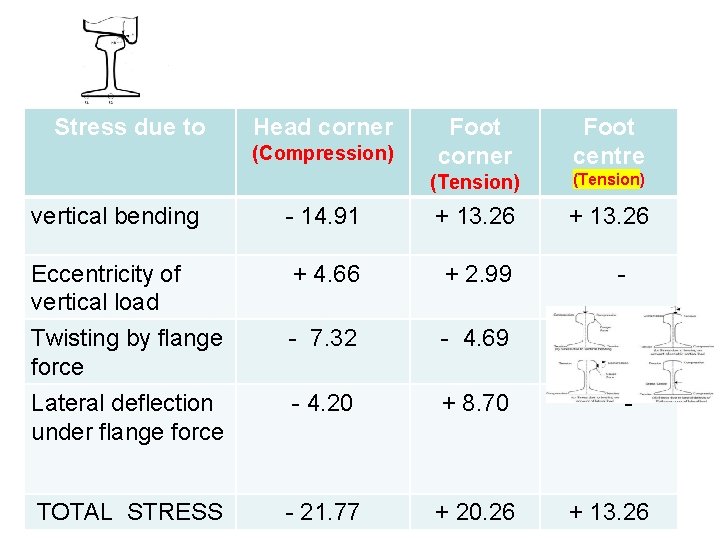
Stress due to Head corner (Compression) Foot corner Foot centre (Tension) + 13. 26 vertical bending - 14. 91 + 13. 26 Eccentricity of vertical load Twisting by flange force Lateral deflection under flange force + 4. 66 + 2. 99 - - 7. 32 - 4. 69 - - 4. 20 + 8. 70 - - 21. 77 + 20. 26 TOTAL STRESS + 13. 26
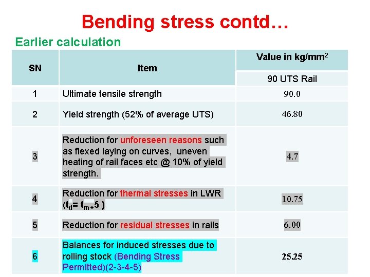
Bending stress contd… Earlier calculation Value in kg/mm 2 SN Item 90 UTS Rail 1 Ultimate tensile strength 90. 0 2 Yield strength (52% of average UTS) 46. 80 3 Reduction for unforeseen reasons such as flexed laying on curves, uneven heating of rail faces etc @ 10% of yield strength. 4. 7 4 Reduction for thermal stresses in LWR (td= tm +5 ) 10. 75 5 Reduction for residual stresses in rails 6. 00 6 Balances for induced stresses due to rolling stock (Bending Stress Permitted)(2 -3 -4 -5) 25. 25
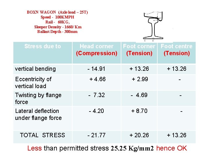
BOXN WAGON (Axle load – 25 T) Speed - 100 KMPH Rail - 60 KG, Sleeper Density - 1660/ Km Ballast Depth - 300 mm Stress due to Head corner (Compression) Foot corner Foot centre (Tension) vertical bending - 14. 91 + 13. 26 Eccentricity of vertical load + 4. 66 + 2. 99 - Twisting by flange force - 7. 32 - 4. 69 - Lateral deflection under flange force - 4. 20 + 8. 70 - - 21. 77 + 20. 26 TOTAL STRESS + 13. 26 Less than permitted stress 25. 25 Kg/mm 2 hence OK
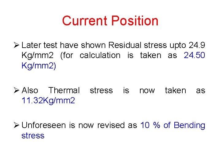
Current Position Ø Later test have shown Residual stress upto 24. 9 Kg/mm 2 (for calculation is taken as 24. 50 Kg/mm 2) Ø Also Thermal 11. 32 Kg/mm 2 stress is now taken as Ø Unforeseen is now revised as 10 % of Bending stress
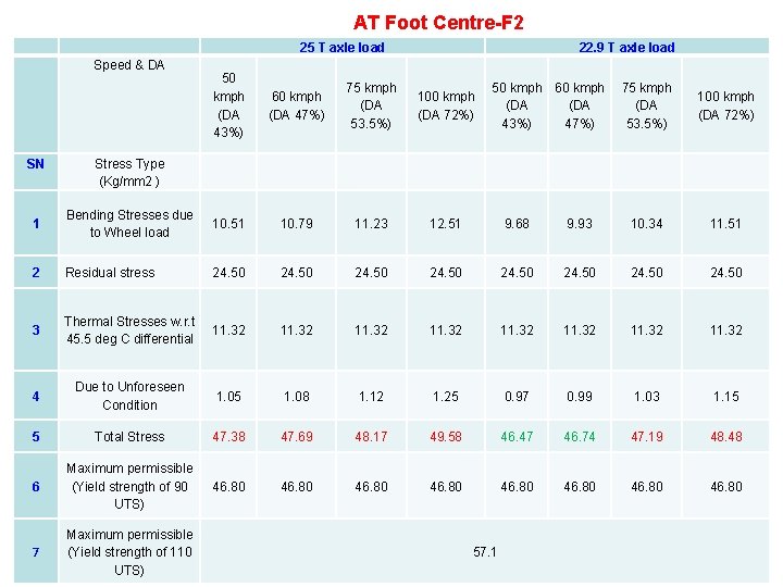
AT Foot Centre-F 2 25 T axle load Speed & DA SN 22. 9 T axle load 50 kmph (DA 43%) 60 kmph (DA 47%) 75 kmph (DA 53. 5%) 100 kmph (DA 72%) 50 kmph 60 kmph (DA 43%) 47%) 75 kmph (DA 53. 5%) 100 kmph (DA 72%) Stress Type (Kg/mm 2 ) 1 Bending Stresses due to Wheel load 10. 51 10. 79 11. 23 12. 51 9. 68 9. 93 10. 34 11. 51 2 Residual stress 24. 50 24. 50 3 Thermal Stresses w. r. t 45. 5 deg C differential 11. 32 11. 32 4 Due to Unforeseen Condition 1. 05 1. 08 1. 12 1. 25 0. 97 0. 99 1. 03 1. 15 5 Total Stress 47. 38 47. 69 48. 17 49. 58 46. 47 46. 74 47. 19 48. 48 6 Maximum permissible (Yield strength of 90 UTS) 46. 80 46. 80 7 Maximum permissible (Yield strength of 110 UTS) 57. 1
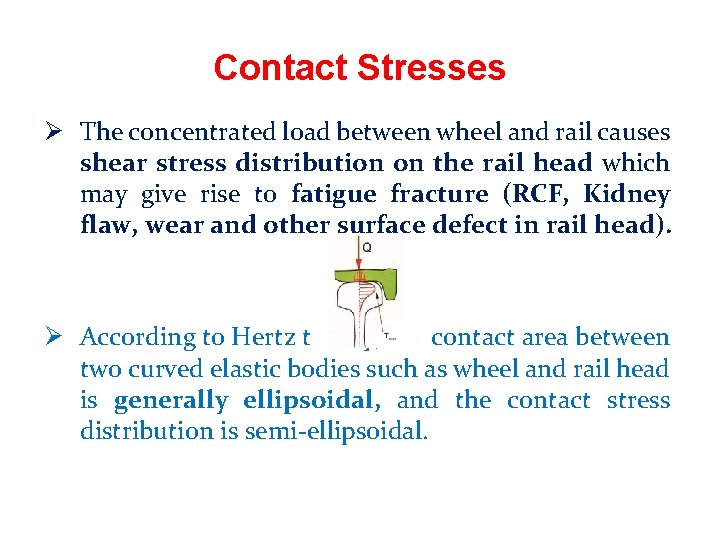
Contact Stresses Ø The concentrated load between wheel and rail causes shear stress distribution on the rail head which may give rise to fatigue fracture (RCF, Kidney flaw, wear and other surface defect in rail head). Ø According to Hertz theory, the contact area between two curved elastic bodies such as wheel and rail head is generally ellipsoidal, and the contact stress distribution is semi-ellipsoidal.
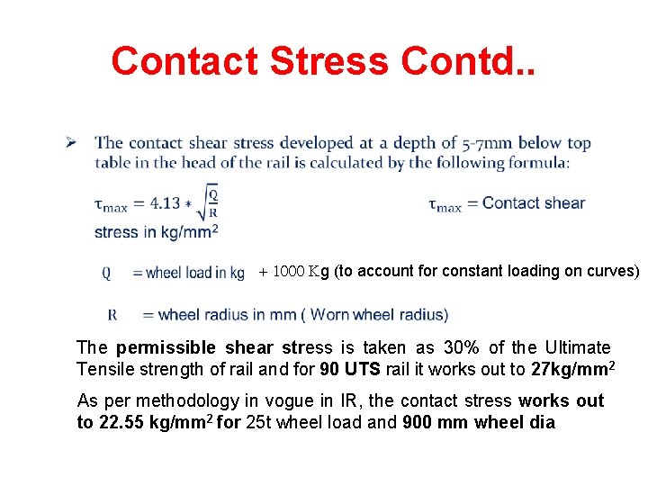
Contact Stress Contd. . + 1000 Kg (to account for constant loading on curves) The permissible shear stress is taken as 30% of the Ultimate Tensile strength of rail and for 90 UTS rail it works out to 27 kg/mm 2 As per methodology in vogue in IR, the contact stress works out to 22. 55 kg/mm 2 for 25 t wheel load and 900 mm wheel dia
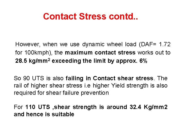
Contact Stress contd. . However, when we use dynamic wheel load (DAF= 1. 72 for 100 kmph), the maximum contact stress works out to 28. 5 kg/mm 2 exceeding the limit by approx. 6% So 90 UTS is also failing in Contact shear stress. The rail of higher shear stress i. e higher Yield strength is also required for shear failure prevention For 110 UTS , shear strength is around 32. 4 Kg/mm 2 and hence is suitable
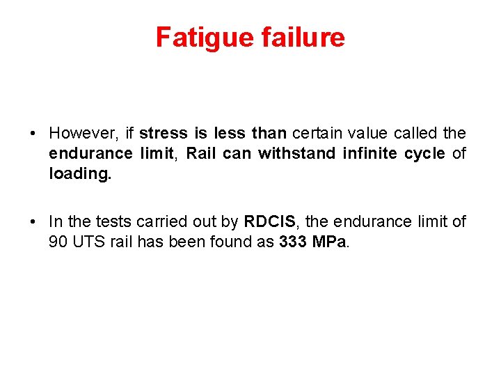
Fatigue failure • However, if stress is less than certain value called the endurance limit, Rail can withstand infinite cycle of loading. • In the tests carried out by RDCIS, the endurance limit of 90 UTS rail has been found as 333 MPa.
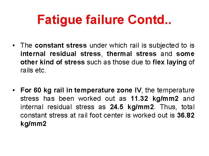
Fatigue failure Contd. . • The constant stress under which rail is subjected to is internal residual stress, thermal stress and some other kind of stress such as those due to flex laying of rails etc. • For 60 kg rail in temperature zone IV, the temperature stress has been worked out as 11. 32 kg/mm 2 and internal residual stress as 24. 5 kg/mm 2. Thus, total constant stress at rail foot center is worked out is 36. 82 kg/mm 2
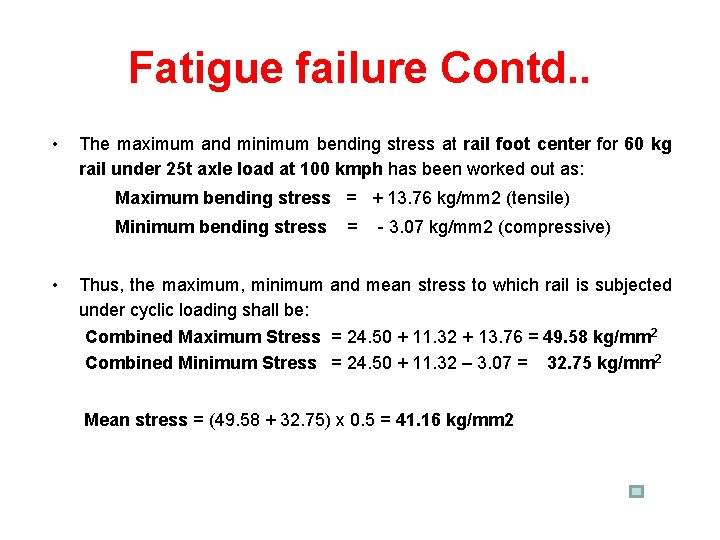
Fatigue failure Contd. . • The maximum and minimum bending stress at rail foot center for 60 kg rail under 25 t axle load at 100 kmph has been worked out as: Maximum bending stress = + 13. 76 kg/mm 2 (tensile) Minimum bending stress • = - 3. 07 kg/mm 2 (compressive) Thus, the maximum, minimum and mean stress to which rail is subjected under cyclic loading shall be: Combined Maximum Stress = 24. 50 + 11. 32 + 13. 76 = 49. 58 kg/mm 2 Combined Minimum Stress = 24. 50 + 11. 32 – 3. 07 = 32. 75 kg/mm 2 Mean stress = (49. 58 + 32. 75) x 0. 5 = 41. 16 kg/mm 2
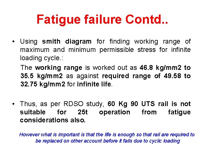
Fatigue failure Contd. . • Using smith diagram for finding working range of maximum and minimum permissible stress for infinite loading cycle. : The working range is worked out as 46. 8 kg/mm 2 to 35. 5 kg/mm 2 as against required range of 49. 58 to 32. 75 kg/mm 2 for infinite life. • Thus, as per RDSO study, 60 Kg 90 UTS rail is not suitable for 25 t operation from fatigue considerations also. However what is important is that the life is enough so that rail are required to be replaced on other account before it fails due to cyclic loading
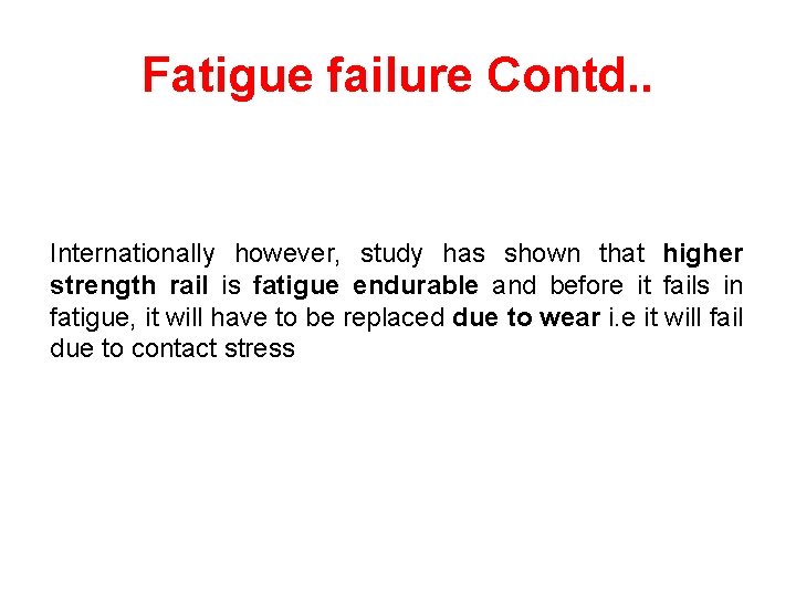
Fatigue failure Contd. . Internationally however, study has shown that higher strength rail is fatigue endurable and before it fails in fatigue, it will have to be replaced due to wear i. e it will fail due to contact stress
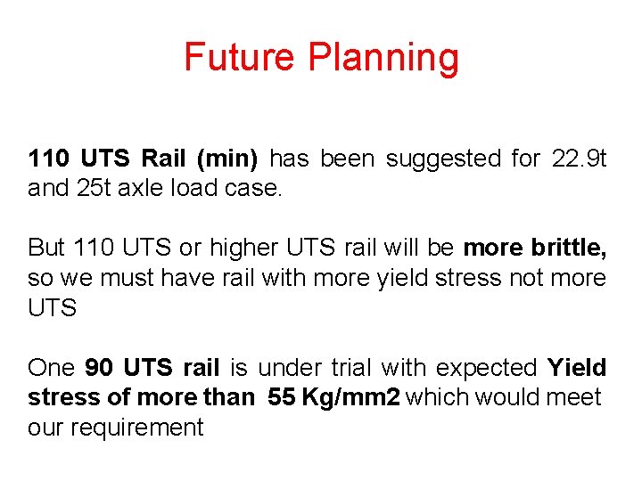
Future Planning 110 UTS Rail (min) has been suggested for 22. 9 t and 25 t axle load case. But 110 UTS or higher UTS rail will be more brittle, so we must have rail with more yield stress not more UTS One 90 UTS rail is under trial with expected Yield stress of more than 55 Kg/mm 2 which would meet our requirement
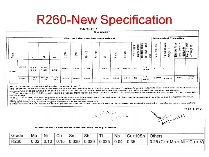
R 260 -New Specification
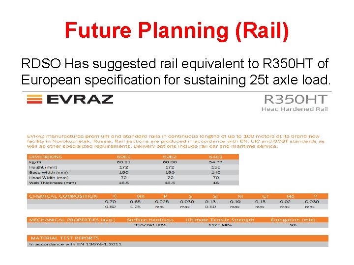
Future Planning (Rail) RDSO Has suggested rail equivalent to R 350 HT of European specification for sustaining 25 t axle load.
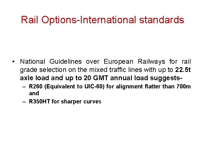
Rail Options-International standards • National Guidelines over European Railways for rail grade selection on the mixed traffic lines with up to 22. 5 t axle load and up to 20 GMT annual load suggests– R 260 (Equivalent to UIC-60) for alignment flatter than 700 m and – R 350 HT for sharper curves
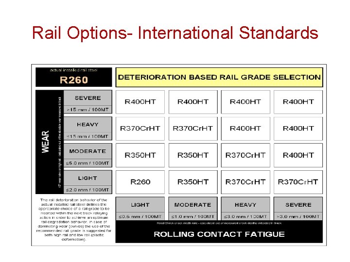
Rail Options- International Standards
Issues In Heavy Axle load Operation On IR affecting Track Major issues in clearance and speed certification of stocks 1. No means for measurement of forces at rail level – Dynamic and impact loading on track at various speeds not assessed 2. Slack criteria for acceptance § no limit for dynamic load ( UIC – max 210 KN) § no limits for acceleration values for freight stock ( UIC – max 0. 5 g vertical, 0. 3 g lateral) Results in to clearing of stocks having more adverse effect on track during operation
Issues In Heavy Axle load Operation On IR affecting Track 3. Oscillation trials on new stocks only – deterioration after service will have more severe effect but no assessment 4. The wagon having reduced wheel diameter (780 mm condemning) –Higher contact stress on rail – increased rate of surface crack propagation, reduced fatigue life and increase risk of inservice sudden failure
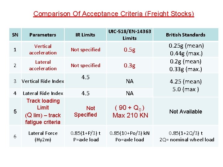
Comparison Of Acceptance Criteria (Freight Stocks) SN Parameters IR Limits UIC-518/EN-14363 Limits 1 Vertical acceleration Not specified 0. 5 g 2 Lateral acceleration Not specified 0. 3 g 3 Vertical Ride Index 4 5 6 Lateral Ride Index Track loading Limit (Q lim) – track fatigue criteria Lateral Force (Hy 2 m) 4. 5 NA British Standards 0. 25 g (mean) 0. 44 g (max. ) 0. 2 g (mean) 0. 33 g (max. ) 4. 25 (mean) 5. 0 (max ) 4. 5 NA Not Specified ( 90 + Q 0 ) Max 210 KN Not Available 0. 85(1+P/3) t P=axle load 0. 85(10+Po/3) k. N Po=axle load 0. 85(1+2 Q/3) t 2 Q= nominal wheel load
Issues In Operation On IR affecting Track 5. High values of accelerations of present heavy axle load wagons in the range of 0. 6 g to 0. 87 g; – high vibrations imparted to rail under high stress condition, reduced fatigue life, increased chances of fatigue and sudden failures No track structure can sustain such high dynamic load & high vibrations
UIC Leaflet 724 -R (track equipment for 25 t axle load on ballasted track) § International study and literature indicate that - Best way to decrease the deteriorating effects on track when operating with high axle load is through reduction in dynamic wheel loads § Pre-conditions for reducing dynamic wheel loads include: - Good track geometry quality - Adapted speed - Good wheel quality - Track friendly vehicle design § However, there are limitations as regards to maintenance of good track geometry and good wheel quality. § So, the track friendly vehicle design becomes most important factor
Instructions issued on IR for running of Heavy Axle load wagons § Install sanctioned Weigh Bridges and ensure that all weigh bridges are kept well maintained and functional. § NO OVERLOADING must be permitted. Drastic penal action should be taken against defaulters. § Good train running and adequate powering should be ensured to prevent instances of stalling/wheel slippages. § Wagons must be well maintained, additional springs as advised be provided during ROH/POH. § WILD (Wheel impact load detector) must be installed at all selected locations within one year. § All remaining instrumentations of bridges etc. should be concluded without any further delay. (Hon’ble MR’s DO letter no MR/M/59/2006 dated 10. 08. 2006)

THANK YOU
- Slides: 83