Radiographic Pathology Cervical Spine Jonathan Mc Connell AP


 1. Prevertebral soft tissue")


 1. Complete anterior")

 1.")


 1. Spinous process")


- Slides: 58
Radiographic Pathology: Cervical Spine Jonathan Mc. Connell
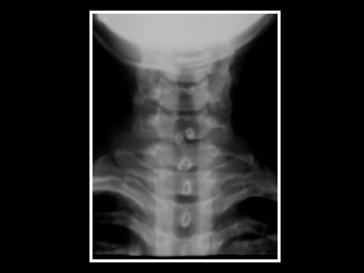
A-P Cervical Spine 1. Bifid spinous process of C 3 2. Superimposed articular processes 3. Uncinate processes 4. Air filled trachea 5. Transverse process of C 7 6. Transverse process of T 1 7. 1 st rib 8. Clavicle 4 th-7 th: The bodies of 4 th to 7 th cervical vertebrae
Lateral Cervical Spine 1. Anterior arch of the atlas 2. Dens of axis 3. Posterior arch of the atlas 4. Soft palate 5. Root of the tongue 6. Transverse process 7. Intervertebral disc 8. Inferior articular process 9. Superior articular process 10. Zygapophyseal (facet) joint 11. Spinous process of C 7 2 nd-7 th: The bodies of 2 nd to 7 th cervical vertebrae
Image Artefacts
OTHER IMPORTANT ANATOMICAL LANDMARKS Line extends from clivus to anterior third of peg Laminar line should intersect posterior foramen magnum Pre dental space < 2 mm in adults may be 4. 5 mm in child C 6 soft tissue thickness 17 mm in adult is suspicious C 2 -4 over 7 mm needs close evaluation
NORMAL VARIANTS INCLUDE YOUNGER PATIENTS • APPARENT SUBLUXATION OF C 2/3 & C 3/4 OF UP TO 3 MM MAY BE SEEN UNTIL 18 YRS OF AGE. • A V SHAPED PRE DENTAL SPACE SHOWING APPARENT WIDENING. • SOFT TISSUE SHADOWS THAT ARE TONSILLAR SWELLINGS RATHER THAN INJURY RESPONSE – DON’T FORGET THE CRYING CHILD WILL SHOW LARGER SOFT TISSUE SHADOWS TOO.
NORMAL VARIANTS ADULT PATIENTS • • • THE OS ODONTOIDEUM THE BIFID SPINOUS PROCESS TIPS INCISOR LINE THE MACH EFFECT ROTATION - ESPECIALLY C 1 - 2
Jefferson Fracture • Odontoid view- lateral displacement of C 1 indicates a Jefferson fracture.
Jefferson Fracture • Description: compression fracture of the bony ring of vertebra C 1, characterized by lateral masses splitting and transverse ligament tear. Mechanism: axial blow to the vertex of the head (e. g. diving injury). Radiographic features: the key radiographic view is the AP open mouth, which shows displacement of the lateral masses of vertebrae C 1 beyond the margins of the body of vertebra C 2. A lateral displacement of >2 mm or unilateral displacement may be indicative of a C 1 fracture. CT is required to define the extent of fracture and to detect fragments in the spinal canal.
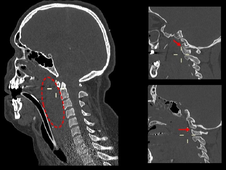
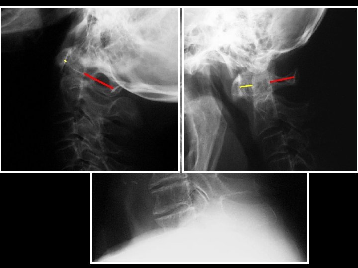
Odontoid Fractures • Radiographic features: Fracture is best seen on lateral view. • Fracture of the odontoid should be suspected if there is an anterior tilt of odontoid on lateral view. • The lucent fracture line may be better delineated by plain film tomogram or CT. • Sometimes the only sign of fracture may be just prevertebral soft tissue swelling. • Odontoid fractures are generally divided into three types.
Odontoid Fracture • Type I Odontoid fracture: Fracture in superior tip of the odontoid. • Potentially unstable. • It is a relatively rare fracture.
Odontoid Fractures • Type II Odontoid Fracture: fracture at base of odontoid. It is the most common type of odontoid fracture. It is an unstable fracture.
Odontoid Fractures • Type III Odontoid Fracture: fracture through base of odontoid into body of axis. It has the best prognosis. The first image an odontoid view, shows the fracture line extendin g beyond the base of the dens. The second image is a CT that confirms the fracture in the body of C 2.
Hangman’s Fracture • Description: fractures through the pars interaticularis of the axis resulting from hyperextension and distraction. Mechanism: hyperextension (e. g. hanging, chin hits dashboard in RTA). Radiographic features: (best seen on lateral view) 1. Prevertebral soft tissue swelling. 2. Avulsion of anterior inferior corner of C 2 associated with rupture of the anterior longitudinal ligament. 3. Anterior dislocation of the C 2 vertebral body. 4. Bilateral C 2 pars interarticularis fractures. Stability: unstable
Hangman’s Fracture • Radiographic features: (best seen on lateral view) 1. Prevertebral soft tissue swelling. 2. Avulsion of anterior inferior corner of C 2 associated with rupture of the anterior longitudinal ligament. 3. Anterior dislocation of the C 2 vertebral body. 4. Bilateral C 2 pars interarticularis fractures.
Hypoplasia of the Dens
Incomplete Arch of C 1
DISLOCATIONS & SUBLUXATIONS ATLANTO AXIAL DISLOCATION • Usually seen at the cranio vertebral junction & is linked with: Rheumatoid arthritis Downs syndrome Ligament laxity after severe head / neck infections may create transient pattern • Rarely noted in trauma when hyperflexion & shearing forces disrupt the transverse ligament of the atlas
DISLOCATIONS & SUBLUXATIONS ATLANTO AXIAL DISLOCATION • Indicators are increase in distance between posterior cortex of anterior arch of atlas & anterior cortex of odontoid peg Adults = < 3 mm Child = <5 mm • This injury may have Jefferson’s components to scrutinise carefully for evidence fracture
DISLOCATIONS & SUBLUXATIONS ATLANTO OCCIPTAL DISLOCATIONS • Usually fatal due to disruption of the medulla oblongata • Lateral projection shows anatomical relations best. Usually accompanied by gross soft tissue swelling • 3 main forms Anterior dislocation of head relative to cervical spine Separation of occiput from atlas by distraction - less common Rarely head will dislocate posteriorly relative to cervical spine
NEUROLOGICAL INJURY THERE ARE RELATIVELY FEW NEUROLOGIC INJURIES OF THE CRANIO-VERTEBRAL JUNCTION • Spinal cord occupies about 50% of canal space • Mechanisms of Jefferson’s, Hangman’s or atlas ring fractures generates canal size increase to protect cord. This is caused by: Centrifugal displacement in Jefferson’s fracture Posterior displacement in C 1 & C 2 neural arch fractures
Cranio-cervical dislocation Beyond obvious A/O separation look at C 2/3 and ST swelling – pt died soon after
C 1 -2 Dislocation
Flexion Teardrop Fracture • Description: posterior ligament disruption and anterior compression fracture of the vertebral body which results from a severe flexion injury. Mechanism: hyperflexion and compression (e. g. diving into shallow water) Radiographic features: (best seen on lateral view) 1. Prevertebral swelling associated with anterior longitudinal ligament tear. 2. Teardrop fragment from anterior vertebral body avulsion fracture. 3. Posterior vertebral body subluxation into the spinal canal. 4. Spinal cord compression from vertebral body displacement. 5. Fracture of the spinous process. Stability: unstable
Flexion Teardrop Fracture
Bilateral Facet Dislocation • Description: complete anterior dislocation of the vertebral body resulting from extreme hyperflexion injury. It is associated with a very high risk of cord damage. Mechanism: extreme flexion of head and neck without axial compression. Radiographic features: (best seen on lateral view) 1. Complete anterior dislocation of affected vertebral body by half or more of the vertebral body AP diameter. 2. Disruption of the posterior ligament complex and the anterior longitudinal ligament. 3. "Bow tie" or " bat wing" appearance of the locked facets. Stability: unstable
Bilateral Facet Dislocation • Radiographic features: (best seen on lateral view) 1. Complete anterior dislocation of affected vertebral body by half or more of the vertebral body AP diameter. 2. Disruption of the posterior ligament complex and the anterior longitudinal ligament. 3. "Bow tie" or " bat wing" appearance of the locked facets. Stability: unstable
Unilateral Facet Dislocation • Description: facet joint dislocation and rupture of the apophyseal joint ligaments resulting from rotatory injury of the cervical vertebrae. Mechanism: simultaneous flexion and rotation
Unilateral Facet Dislocation • Radiographic features: (best seen on lateral or oblique views) 1. Anterior dislocation of affected vertebral body by less than half of the vertebral body AP diameter. 2. Discordant rotation above and below involved level. 3. Facet within intervertebral foramen on oblique view. 4. Widening of the disk space. 5. "Bow tie" or "bat wing" appearance of the overriding locked facets. Stability: stable Perched or locked facets
C 4 -C 5 unilateral facet dislocation“Bowtie sign” The "bowtie sign" on a lateral view radiograph is indicative of the presence of a unilateral facet dislocation. The scheme is created by the misaligned pedicles of the dislocated vertebra.
Anterior Subluxation • Description : disruption of the posterior ligamentous complex resulting from hyperflexion. It may be difficult to diagnose because muscle spasm may result in similar findings on the radiograph. Subluxation may be stable initially, but it associates with 20%-50% delayed instability. Flexion and extension views are helpful in further evaluation. Mechanism: hyperflexion of neck
C 5 -6 Subluxation
Anterior Subluxation • Radiographic features: 1. Loss of normal cervical lordosis. 2. Anterior displacement of the vertebral body. 3. Fanning of the interspinous distance. Radiographic features of unstable injury: 1. Anterior subluxation of more than 4 mm. 2. Associated compression fracture of more than 25 % of the affected vertebral body. 3. Increase or decrease in normal disk space. 4. Fanning of the interspinous distance.
Clay Shovellers Fracture • Description: fracture of a spinous process C 6 -T 1 Mechanism: powerful hyperflexion, usually combined with contraction of paraspinous muscles pulling on spinous processes (e. g. shovelling).
Clay Shovellers Fracture • Radiographic features: (best seen on lateral view) 1. Spinous process fracture on lateral view. 2. Ghost sign on AP view (i. e. double spinous process of C 6 or C 7 resulting from displaced fractured spinous process). Stability: stable
Wedge Fracture • Description: compression fracture resulting from flexion. Mechanism: hyperflexion and compression Radiographic features: 1. Buckled anterior cortex. 2. Loss of height of anterior vertebral body. 3. Anterosuperior fracture of vertebral body. Stability: stable
Wedge Fracture
Burst Fracture • Description: fracture of C 3 -C 7 that results from axial compression. Injury to spinal cord, secondary to displacement of posterior fragments, is common. CT is required for all patient to evaluate extent of injury. Mechanism: axial compression Stability: stable
Burst Fracture
Stability Classification review
Prevertebral Soft Tissues • A prevertebral soft tissue thickness of 7 mm or more in front of the antero-inferior extremity of C 2 to C 4 suggests an injury. • Lower down, from C 4 to T 1, the prevertebral soft tissues are thicker and an injury should only be suspected when the thickness exceeds 17 mm.
Prevertebral Soft Tissue Thickening • Prevertebral soft tissue swelling can be caused by injuries to: • Anterior longitudinal ligament • Anterior part of a vertebral body or intervertebral disc • The dens or to the anterior arch of the atlas, at the cranio-cervical articulation
Prevertebral Soft Tissue Swelling
Gas in the Prevertebral space Most likely represents either ruptured oesophagus or trachea
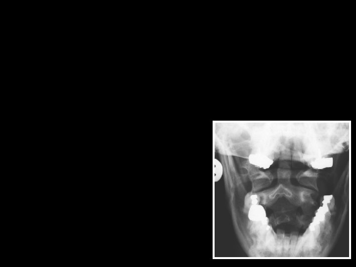
Foreign body in hypopharynx
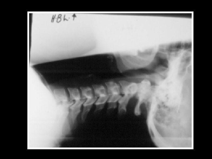
Occluded intervertebral foramen: Severe OA
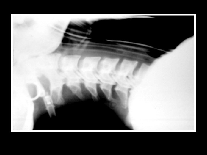
Surgical fusion C 4/5 Similar features may be seen post infection/discitis where ankylosis occurs during healing
Klippel Feil syndrome • • Vertebral formation or segmentation defects in 2 or more of cervical vertebrae Short neck Scoliosis, spina bifida, cleft palate, low hairline Kidney, heart and respiratory anomalies
Ankylosing spondylitis
Rheumatoid arthritis
Metastases
Thanks for your attention!!