RADIOGRAPHIC EQUIPMENT Adler Carlton Ch 8 Bushong Ch

RADIOGRAPHIC EQUIPMENT Adler & Carlton Ch. 8 & Bushong Ch. 1

Modern radiology l Two basic types of x-ray examinations • Radiography • Fluoroscopy 2

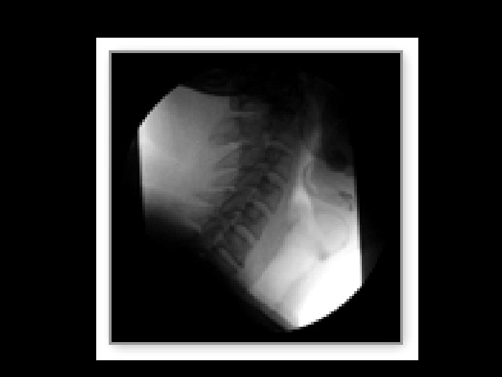
Radiography exam 3

Radiographic Room

The transformation from a physicist toy to a valuable, large scale medical specialty • 1907 Snook transformer – high voltage • 1913 Coolidge x-ray tube – air evacuated, separate selection of voltage and current • Standardizing x-ray tube beam output 6

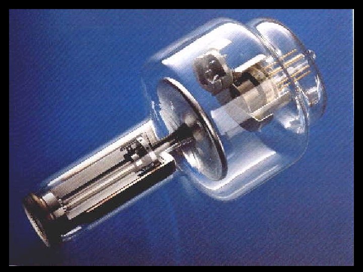
THE X-RAY TUBE • The X-Ray tube is the single most important component of the radiographic system. It is the part that produces the xrays

THE X-RAY TUBE • GLASS ENCASED IN STURDY STEEL HOUSING • PRIMARY COMPONENTS – ANODE + – CATHODE --
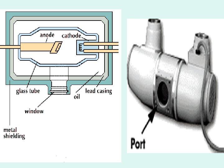

XRAY TUBE HOUSING • MADE OF LEAD AND STEEL • TO ABSORB ANY STRAY RADIATION • TO PREVENT LEAKAGE RADIATION FROM THE TUBE

TUBE HOUSING MADE OF LEAD & STEEL
 Adler & Carlton TO")
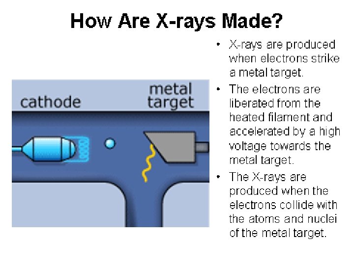
How “X-rays” are created SEE: MAN MADE RADIATION (PG. 111) Adler & Carlton TO PRODUCE X-RAYS YOU NEED: • A SOURCE OF ELECTONS • A FORCE TO MOVE THEM QUICKLY • SOMETHING TO STOP THEM SUDDENLY

How “X-rays” are created • Power is sent to x-ray tube via cables • m. A (milliamperage) is sent to filament on cathode side. • Filament heats up – electrons “boil off” • Negative charge

How “X-rays” are created • Positive voltage is applied to ANODE • Negative electons = attracted across the tube to the positive ANODE. • Electrons “slam into” anode – suddenly stopped. • X-RAY PHOTONS ARE CREATED

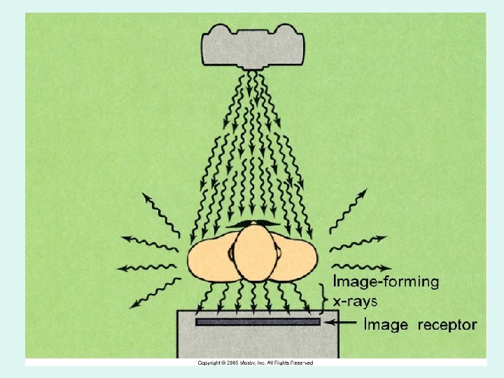
How “X-rays” are created • Electron beam is focused from the cathode to the anode target by the focusing cup • Electrons interact with the electrons on the tungsten atoms of target material • PHOTONS sent through the window PORT – towards the patient

More on the tube later……. .

X-RAY TABLE
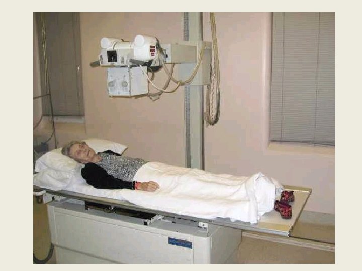


Radiographic tables l l l Are designed to support the patient during a radiographic exam Comfort is not the primary concern Foam pads should be used if the patient will be required to be on the table for longer than 10 minutes

Tabletop l l l Must be uniformly radiolucent to easily permit x-ray to pass through. Carbon fiber is used because it is strong and very little x-ray photons are absorbed. Usually tabletops are flat however some are curved

Tabletop l l Most tabletops are floating, some are motor-driven The brakes can be released usually by the technologist hand or foot The brakes are electromagnetic Floating table tops save significant amounts of time and strain on the technologist

Tables l l Tables are fixed or tilting Fixed rooms are designed for diagnostic radiographic work only • The table can usually be raised or lowered to accommodate the patient and the technologist.

Table top technique l l Performing imaging using just the cassette, plate or digital image receptor Also called “nongrid” technique

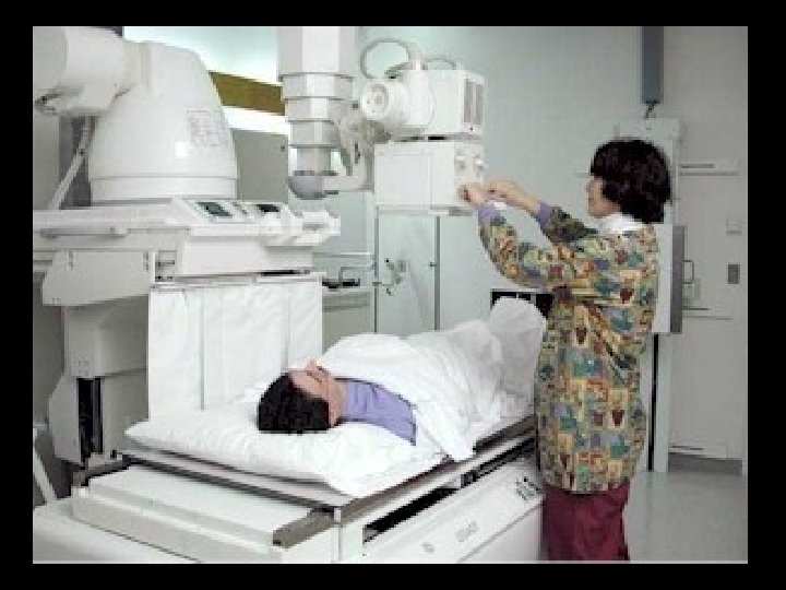
Fluoroscopy exam 26

FLUOROSCOPY IMAGES IN MOTION

Fluoroscope 1898 by Thomas Edison 28

Radiation Injury 1904 the first recorded x-ray fatality in the US – Clarence Dally, Edison’s assistant Early injuries took the form of skin damage, loss of hair and anemia Snook transformer & Coolidge tube reduced the injuries Why? 29

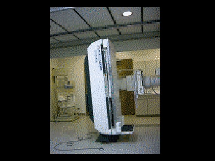
Tables l Tilting rooms are designed for both diagnostic and fluoroscopic work • Tilting models usually tilt to 90 degrees in one direction and 15 – 30 degrees in the other direction • Tilting models include ancillary equipment; footboard, shoulder support, handgrips, compression bands
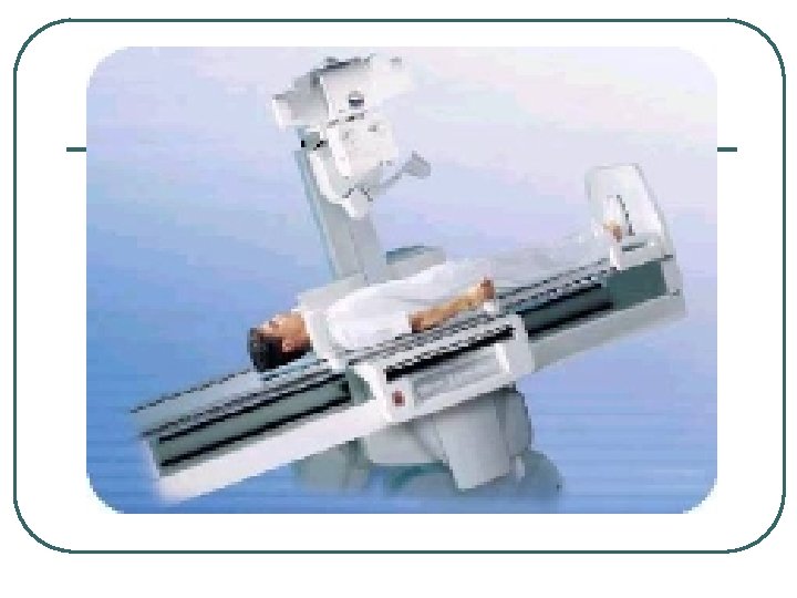

Table Movement l l Longitudinal Transverse Vertical Tilt or Angling

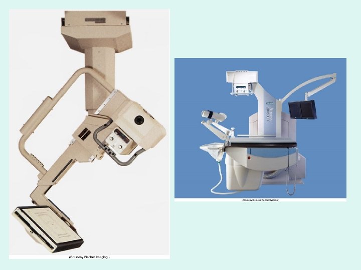
Fluoroscopy tables: the tube is under the table, image capture is above the patient
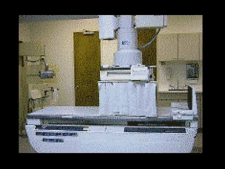

Tube Supports l l Designed to help technologists with various tube locations for creative imaging. Tube suspension systems are available in 5 versions: • ceiling mounted, floor-to-ceiling, floor, mobile and c-arm.
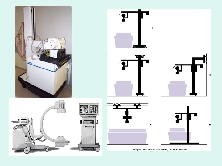

Tube Movement • • • Longitudinal Transverse Vertical Angling or Rolling Rotating Telescoping

Improvement in radiography l Reducing exposure time to reduce blur l Dentist William Rollins began using a diaphragm to improve image quality • First application of collimation and filtration l 1921 Potter-Bucky grid – improving image contrast 42

Dr. William Rollins • Dr. William Rollins was a Boston physician and dentist who was the first to use collimation and filtration in the late 1800 s. • After receiving radiation burns to his hand in x-ray experiments in 1898, he used leather and aluminum filters when he made x-ray exposures of his patients' teeth. 43

The ‘BUCKY’ • The Potter-Bucky is the device in the table or chest board that holds the film cassette. The ‘bucky’ is like a drawer that opens and closes to insert and remove the film cassette.

TABLE OR UPRIGHT BUCKY TRAY

Radiographic grid ?
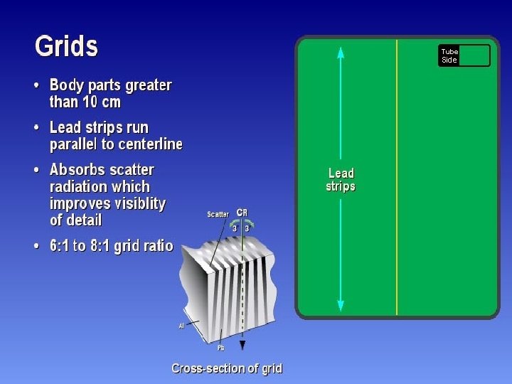
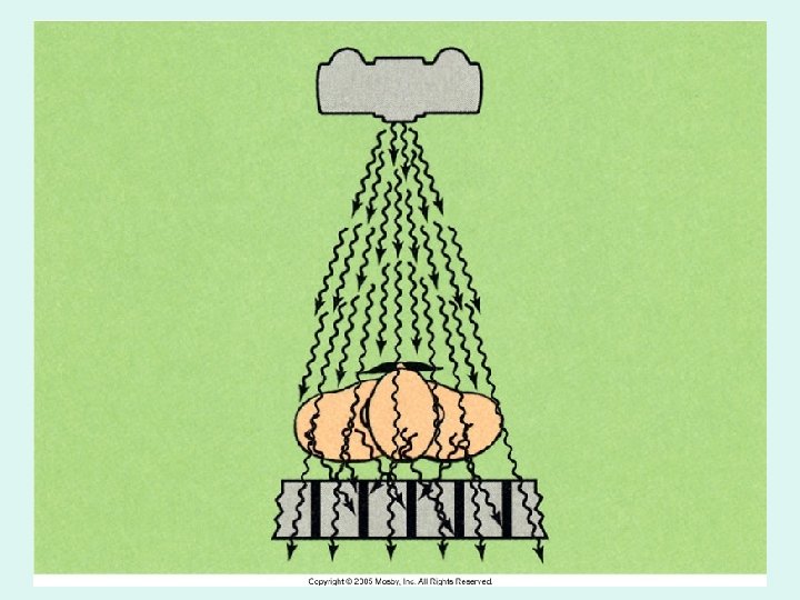

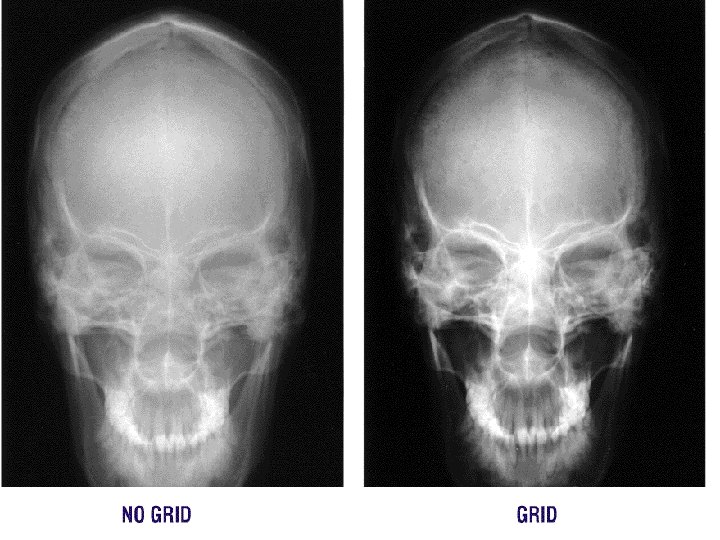
Bucky cross hatched • Grids are used to “clean up” scatter radiation from the patient • To improve • contrast on the radiograph • Potter-Bucky are usually a focused moving grid

CASSETTES W/ GRID CAPS

Radiation shields

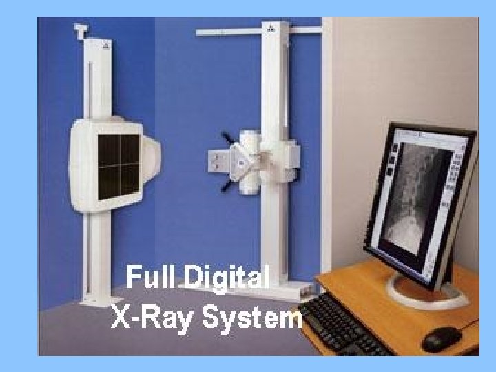
Viewing images • View boxes • Computer monitors

COLLIMATOR • ATTACHES DIRECTLY BELOW THE X-RAY TUBE • SERVES AS A X-RAY BEAM LIMITING DEVISE • CONTROLS THE SIZE AND SHAPE OF X-RAY FIELD

Cone collimator

• ALWAYS KEEP THE COLLIMATED AREA SMALLER THAN THE SIZE OF THE CASSETTE

X-ray tube controls • Displays – Tube angle – Distance to table top bucky – Collimator controls – Tube lock controls – High voltage cables

CASSETTE or FILM HOLDER • The CASSETTE is used to hold the film during examinations. It consist of front and back intensifying screens, and has a lead (Pb) backing. The cassette is light tight

• CR image capture • PSP Plate • PHOTOSTIMULABLE PHOSPHOR PLATE

FILM direct exposure & screen-film or film-screen SIZES 14 X 17 14 X 14 11 X 14 10 X 12 8 X 10

Film Sizes Standard “inches”: Metric: 8” x 10” 18 cm x 24 cm 10” x 12” 24 cm x 30 cm 11” x 14” 30 cm x 35 cm 14” x 17” 35 cm x 43 cm
 • Collection element • TFT (Thin film transistor) • Photodiode •")
• DR(DDR) • Collection element • TFT (Thin film transistor) • Photodiode • CCD (charge-coupled device)

CONTROL CONSOLE • GIVES THE TECHNOLOGIST CONTROL OF THE X -RAY MACHINE • TECHNIQUE SELECTION • Located OUTSIDE of the Radiographic Room
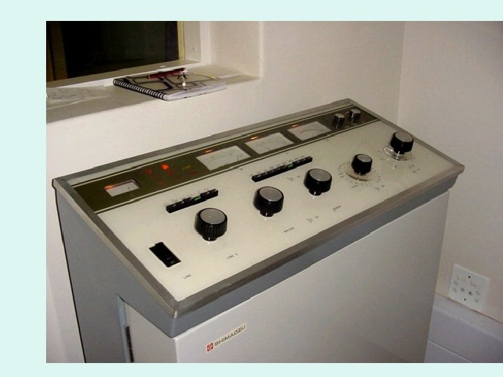

The Control Console • The control console is device that allows the technologist to set technical factors (m. As & k. Vp) and to make an exposure. • Only a legally licensed individual is authorized to energize the console.
 • What is set")
“Technique” k. Vp , m. As (m. A x s) • What is set at the control panel • How the “image” is created on the “film” or Image receptor (digital) • k. Vp controls the “ENERGY” of the beam • The Higher k. Vp – more penetrating • Ranges is 50 -110 in Diagnostic x-ray

+ 30% + 50 % mas

k. Vp Changes

Darkroom
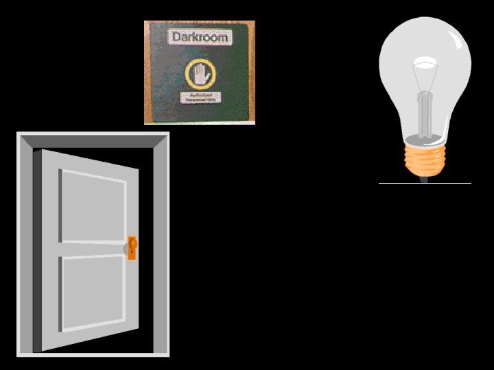

What is in the Darkroom?

Safe Light • 15 Watts • Red filter • Must be 3 -6 feet from counter top or feed tray of processor • Used to be amber or orange filter
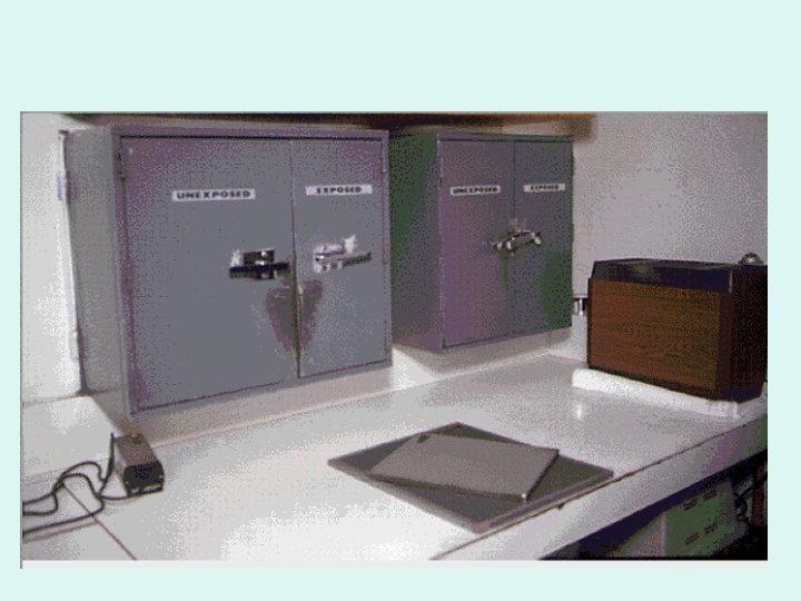
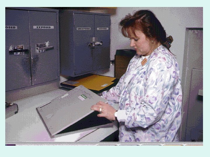

UNLOAD EXPOSED FILM

FILM ID PRINTER

FILM BIN - STORAGE
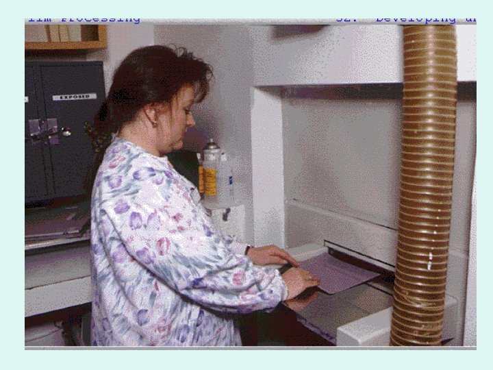
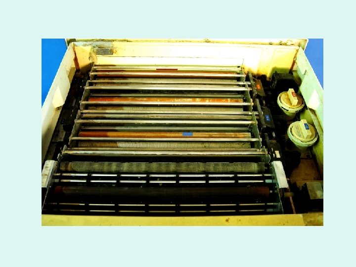
 Feed Tray Entrance Deep Racks Turnarou nd Crossover Squeegee Dryer")
Transport System (Rollers) Feed Tray Entrance Deep Racks Turnarou nd Crossover Squeegee Dryer

Analog processor

CR processor • What does a DDR processor look like?

Other x-ray stuff…. • Positioning phantoms • Pixie

Dosimeter l l An instrument that detects and measures exposures to ionizing radiation Personal vs Field survey instruments

Densitometer l Measures optical density on a radiograph

Step wedge or penetrometer l l Test tool made from aluminum Accurately-calibrated filter strip that provides a stepped range of exposures

Other x-ray stuff…. • Positioning sponges • Lead markers • Gurney
- Slides: 90