RADIO INTERFACE PROTOCOLS 7 1 Introduction 7 2


")


 SAPs")
 protocol for dealing with data words that are corrupted")

 in the control plane called Radio")
 exists only for PS domain services main function")
 used to convey over the radio interface messages")
, which")


 layer logical")


 one MAC-b entity in each UE one")
 Forward Link")
 one MAC-c/sh")
 allocated to a UE in connected")


 where data is")
 selection for RACH transmission PRACH resources (i. e. access")

 a downlink channel for broadcasting system control")
 a point-to-point bidirectional channel that transmits dedicated control information")
 a bidirectional channel for transmitting control information between the")
 a point-to point channel, dedicated to one")

![DCCH and DTCH can be connected to RACH [up] and FACH [down] CPCH [up]](https://slidetodoc.com/presentation_image/2b433e1ee711131d2b4dfb9ec206927e/image-42.jpg "DCCH and DTCH can be connected to RACH [up] and FACH [down] CPCH [up]")


 error detection is performed on")


 mechanism is used for error")


 in layered systems, a unit of data that is")


 protocol service-specific Layer 2 protocol")


 is being added")


")


 messages the major")


, but some messages are sent using unacknowledged")
 handles paging of idle mode UE(s)")

 handles the system information broadcasting there is at")
 normally drawn outside of the RRC protocol and ‘logically’")


 in the MAC PDU header")

 is also capable of receiving BMC")


 after")


- Slides: 126
RADIO INTERFACE PROTOCOLS
7. 1 Introduction 7. 2 Protocol Architecture 7. 3 The Medium Access Control Protocol 7. 4 The Radio Link Control Protocol 7. 5 The Packet Data Convergence Protocol 7. 6 The Broadcast/Multicast Control Protocol 7. 7 Multimedia Broadcast Multicast Service 7. 8 The Radio Resource Control Protocol
7. 1 INTRODUCTION The protocol layers above physical layer Data Link Layer (Layer 2) Network Layer (Layer 3) In UTRA FDD radio interface, Layer 2 is split into sublayers in control plane, Layer 2 contains two sub-layers Medium Access Control (MAC) protocol Radio Link Control (RLC) protocol
in user plane, in addition to MAC and RLC, two additional service-dependent protocols Packet Data Convergence Protocol (PDCP) Broadcast/Multicast Control Protocol (BMC) In UTRA FDD radio interface, Layer 3 consists of one protocol Radio Resource Control (RRC), which belongs to control plane
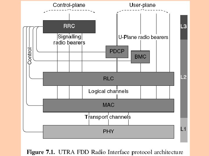
7. 2 PROTOCOL ARCHITECTURE Figure 7. 1 shows the overall radio interface protocol architecture contains only the protocols that are visible in UTRAN
Physical layer offers services to MAC layer via transport channels are characterized by how and with what characteristics data is transferred MAC layer offers services to RLC layer by means of logical channels are characterized by what type of data is transmitted
RLC layer offers services to higher layers via service access points (SAPs) SAPs describe how the RLC layer handles the data packets and if, for example, the automatic repeat request (ARQ) function is used
註: Automatic Repeat Request (ARQ) protocol for dealing with data words that are corrupted by errors whereby the receiving system requests a retransmission of the word(s) in error
on the control plane RLC services are used by RRC layer for signaling transport on the user plane RLC services are used by either of the following the service-specific protocol layers PDCP or BMC other higher-layer uplane functions (e. g. speech codec)
RLC services called Signaling Radio Bearers (SRB) in the control plane called Radio Bearers in the user plane RLC protocol operates in three modes transparent mode unacknowledged mode
Packet Data Convergence Protocol (PDCP) exists only for PS domain services main function is header compression the services offered by PDCP are called Radio Bearers
Broadcast Multicast Control protocol (BMC) used to convey over the radio interface messages originating from Cell Broadcast Centre Release’ 99, the only specified broadcasting service is SMS Cell Broadcast service, which is derived from GSM the service offered by BMC protocol is also called a Radio Bearer
RRC layer offers services to higher layers via service access points (SAP), which are used by the higher layer protocols in the UE side the Iu RANAP protocol in the UTRAN side all higher layer signaling (mobility management, call control, session management, etc. ) is encapsulated into RRC messages for transmission over radio interface
SIGNALING AND TRAFFIC CONNECTIONS BETWEEN MOBILE AND SGSN
The control interfaces between RRC and all the lower layer protocols are used by RRC layer to configure characteristics of the lower layer protocol entities including parameters for the physical, transport and logical channels command the lower layers to perform certain types of measurement report measurement results and errors to RRC
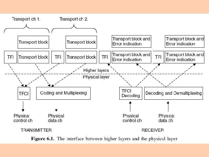
7. 3 THE MEDIUM ACCESS CONTROL PROTOCOL In Medium Access Control (MAC) layer logical channels are mapped to transport channels MAC layer responsible for selecting an appropriate transport format (TF) for each transport channel depending on the instantaneous source rate(s) of logical channels the transport format is selected w. r. t the transport format combination set (TFCS) which is defined by the admission control for each connection
7. 3. 1 MAC Layer Architecture 7. 3. 2 MAC Functions 7. 3. 3 Logical Channels 7. 3. 4 Mapping Between Logical Channels and Transport Channels
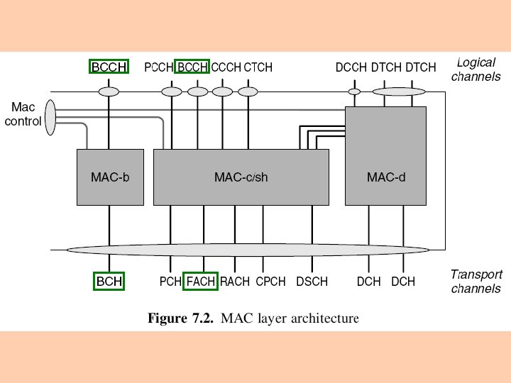
7. 3. 1 MAC LAYER ARCHITECTURE Figure 7. 2 shows the MAC layer logical architecture MAC layer consists of three logical entities MAC-b MAC-c/sh MAC-d
MAC-b handles the broadcast channel (BCH) one MAC-b entity in each UE one MAC-b in the UTRAN (located in Node B) for each cell
MAC-c/sh handles the common channels and shared channels Paging Channel (PCH) Forward Link Access Channel (FACH) Random Access Channel (RACH) Uplink Common Packet Channel (CPCH) Downlink Shared Channel (DSCH)
one MAC-c/sh entity in each UE that is using shared channel(s) one MAC-c/sh in the UTRAN (located in the controlling RNC) for each cell BCCH logical channel can be mapped to either BCH or FACH transport channel
MAC-d responsible for handling dedicated channels (DCH) allocated to a UE in connected mode one MAC-d entity in UE one MAC-d entity in UTRAN (in the serving RNC) for each UE
7. 3. 2 MAC FUNCTIONS Mapping mapping between logical channels and transport channels Transport Format selection of appropriate Transport Format (from the Transport Format Combination Set, TFCS) for each Transport Channel, depending on the instantaneous source rate
Priority handling priority handling between data flows of one UE achieved by selecting ‘high bit rate’ and ‘low bit rate’ transport formats for different data flows priority handling between UEs by means of dynamic scheduling a dynamic scheduling function may be applied for common and shared downlink transport channels FACH and DSCH
Identification of UEs on common transport channels when a common transport channel (RACH, FACH or CPCH) carries data from dedicated-type logical channels (DCCH, DTCH), the identification of the UE (Cell Radio Network Temporary Identity (C-RNTI) or UTRAN Radio Network Temporary Identity (U-RNTI)) is included in the MAC header
Multiplexing/demultiplexing of higher layer PDUs into/from transport blocks delivered to/from the physical layer on common transport channels MAC handles service multiplexing for common transport channels (RACH/FACH/CPCH)
Multiplexing / demultiplexing of higher layer PDUs into/from transport block sets delivered to/from the physical layer on dedicated transport channels MAC allows service multiplexing also for dedicated transport channels MAC multiplexing is possible only for services with the same Qo. S parameters physical layer multiplexing is possible to multiplex any type of service, including services with different Qo. S parameters
Traffic volume monitoring MAC receives RLC PDUs together with status information on the amount of data in the RLC transmission buffer MAC compares the amount of data corresponding to a transport channel with the thresholds set by RRC if the amount of data is too high or too low, MAC sends a measurement report on traffic volume status to RRC
RRC can also request MAC to send these measurements periodically RRC uses these reports for triggering reconfiguration of Radio Bearers and/or Transport Channels
Dynamic Transport Channel type switching execution of the switching between common and dedicated transport channels is based on a switching decision derived by RRC Ciphering if a radio bearer is using transparent RLC mode, ciphering is performed in the MAC sub-layer (MAC-d entity)
Ciphering is a XOR operation (as in GSM and GPRS) where data is XORed with a ciphering mask produced by a ciphering algorithm in MAC ciphering, the time-varying input parameter (COUNT-C) for the ciphering algorithm is incremented at each transmission time interval (TTI), that is, once every 10, 20, 40 or 80 ms depending on the transport channel configuration each radio bearer is ciphered separately the ciphering details are described in 3 GPP specification TS 33. 102
Access Service Class (ASC) selection for RACH transmission PRACH resources (i. e. access slots and preamble signatures [前導簽章,用於區別用戶] for FDD) may be divided between different Access Service Classes in order to provide different priorities of RACH usage the maximum number of ASCs is eight MAC indicates the ASC associated with a PDU to the physical layer
7. 3. 3 LOGICAL CHANNELS The data transfer services of the MAC layer are provided on logical channels Logical channels are classified into two groups control used to transfer control plane information traffic channels used to transfer user plane information
Control Channels Broadcast Control Channel (BCCH) a downlink channel for broadcasting system control information Paging Control Channel (PCCH) a downlink channel that transfers paging information
Dedicated Control Channel (DCCH) a point-to-point bidirectional channel that transmits dedicated control information between a UE and RNC this channel is established during RRC connection establishment procedure
Common Control Channel (CCCH) a bidirectional channel for transmitting control information between the network and UEs this logical channel is always mapped onto RACH/FACH transport channels a long UTRAN UE identity is required (U-RNTI, which includes SRNC address) so that the uplink messages can be routed to the correct serving RNC even if the RNC receiving the message is not the serving RNC of this UE
Traffic Channels Dedicated Traffic Channel (DTCH) a point-to point channel, dedicated to one UE, for the transfer of user information can exist in both uplink and downlink Common Traffic Channel (CTCH) a point-to-multipoint downlink channel for transfer of dedicated user information for all, or a group of specified, UEs
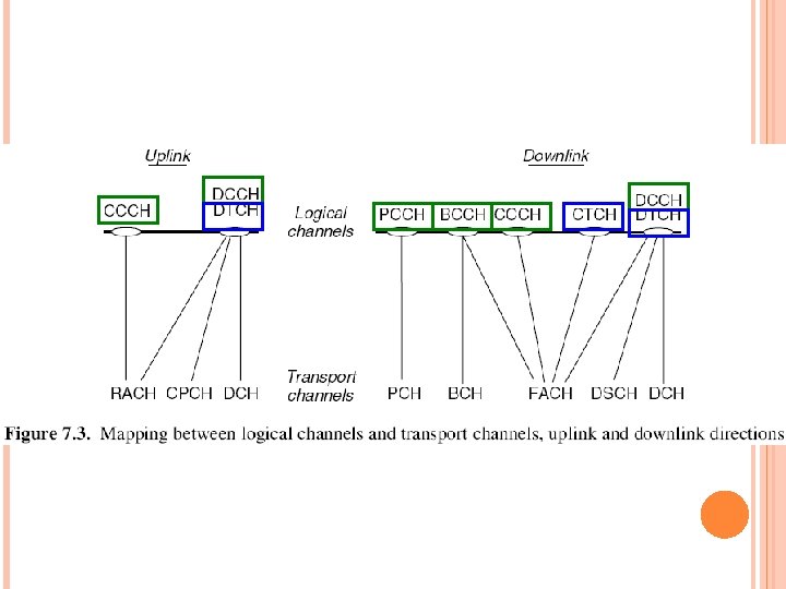
7. 3. 4 MAPPING BETWEEN LOGICAL CHANNELS AND TRANSPORT CHANNELS Figure 7. 3 shows the mapping between logical channels and transport channels Connections between logical channels and transport channels PCCH is connected to PCH [down] BCCH is connected to BCH [down] and may also be connected to FACH [down]
DCCH and DTCH can be connected to RACH [up] and FACH [down] CPCH [up] and FACH [down] RACH [up] and DSCH [down] DCH [up] and DCH [down] CCCH is connected to RACH [down] and FACH [down] CTCH is connected to FACH [down]
7. 4 THE RADIO LINK CONTROL PROTOCOL RLC protocol provides segmentation and retransmission services for both user and control data Each RLC instance is configured by RRC to operate in one of three modes Transparent mode (Tr) Unacknowledged Mode (UM) Acknowledged Mode (AM)
The service the RLC layer provides in the control plane called Signaling Radio Bearer (SRB) in the user plane called Radio Bearer (RB) service provided by PDCP, BMC protocols, or else
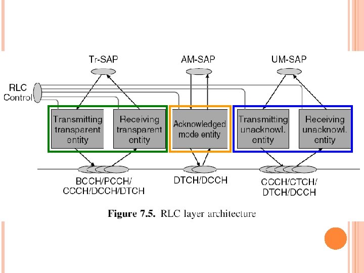
7. 4. 1 RLC LAYER ARCHITECTURE Figure 7. 5 shows the RLC layer architecture all three RLC entity types and their connection to RLCSAPs and to logical channels (MAC-SAPs) are shown the transparent and unacknowledged mode RLC entities are defined to be unidirectional the acknowledged mode entities are described as bidirectional
For all RLC modes CRC (Cyclic Redundancy Check) error detection is performed on physical layer the result of CRC check is delivered to RLC, together with the actual data
In transparent mode no protocol overhead is added to higher layer data erroneous protocol data units (PDUs) can be discarded or marked erroneous example transmission can be of the streaming type
In unacknowledged mode no retransmission protocol is in use and data delivery is not guaranteed received erroneous data is either marked or discarded depending on the configuration on the sender side, a timer-based discard without explicit signaling function is applied RLC SDUs which are not transmitted within a specified time are simply removed from the transmission buffer
an RLC entity in unacknowledged mode is defined as unidirectional because no association between uplink and downlink is needed example of user services using unacknowledged mode RLC cell broadcast service Voice over IP (Vo. IP)
In acknowledged mode an automatic repeat request (ARQ) mechanism is used for error correction the quality vs. delay performance of RLC can be controlled by RRC through configuration of the number of retransmissions provided by RLC in case RLC is unable to deliver the data correctly (max number of retransmissions reached or the transmission time exceeded) the upper layer is notified and the RLC SDU (Service Data Unit) is discarded
RLC can be configured for both in-sequence and out-ofsequence delivery in-sequence delivery the order of higher layer PDUs is maintained out-of-sequence delivery forwards higher layer PDUs as soon as they are completely received the acknowledged mode is the normal RLC mode for packet-type services, examples Internet browsing email downloading
7. 4. 2 RLC FUNCTIONS Segmentation and reassembly performs segmentation/reassembly of variable-length higher layer PDUs into/from smaller RLC Payload Units (PUs) one RLC PDU carries one PU the RLC PDU size is set according to the smallest possible bit rate for the service using RLC entity
註: Protocol Data Unit (PDU) in layered systems, a unit of data that is specified in a protocol of a given layer and that consists of protocol-control information of the given layer possibly user data of that layer
for variable rate services, several RLC PDUs need to be transmitted during one transmission time interval when any bit rate higher than the lowest one is used
Concatenation if the contents of an RLC SDU do not fill an integral number of RLC PUs, the first segment of the next RLC SDU may be put into the RLC PU in concatenation with the last segment of the previous RLC SDU 2 SDU 1 PU 2 PU 3 PU 4 PU 5 PU 6
Padding when concatenation is not applicable and the remaining data to be transmitted does not fill an entire RLC PDU of given size, the remainder of the data field is filled with padding bits Transfer of user data RLC supports acknowledged, unacknowledged and transparent data transfer of user data is controlled by Qo. S setting
Error correction provides error correction by retransmission in the acknowledged data transfer mode In-sequence delivery of higher layer PDUs preserves the order of higher layer PDUs that were submitted for transfer by RLC using the acknowledged data transfer service if this function is not used, out-of-sequence delivery is provided
Duplicate detection detects duplicated received RLC PDUs and ensures that the resultant higher layer PDU is delivered only once to the upper layer Flow control allows an RLC receiver to control the rate at which the peer RLC transmitting entity may send information
Sequence number check guarantees the integrity of reassembled PDUs provides a means of detecting corrupted RLC SDUs through checking the sequence number in RLC PDUs when they are reassembled into an RLC SDU a corrupted RLC SDU is discarded
Protocol error detection and recovery detects and recovers from errors in the operation of RLC protocol Ciphering performed in the RLC layer for acknowledged and unacknowledged RLC modes
the same ciphering algorithm is used as for MAC layer ciphering the only difference being the time-varying input parameter (COUNT-C) for the algorithm, which for RLC is incremented together with the RLC PDU numbers for retransmission the same ciphering COUNT-C is used as for the original transmission; this would not be so if ciphering were on the MAC layer ciphering details are described in 3 GPP specification TS 33. 102
Suspend/resume function for data transfer suspension is needed during the security mode control procedure so that the same ciphering keys are always used by the peer entities suspensions and resumptions are local operations commanded by RRC via control interface
7. 5 THE PACKET DATA CONVERGENCE PROTOCOL PDCP exists only in the user plane and only for services from PS domain PDCP contains compression methods which are needed to get better spectral efficiency for services requiring IP packets to be transmitted over the radio For 3 GPP Release ’ 99 standards a header compression method is defined, for which several header compression algorithms can be used
Example of why header compression is valuable the size of the combined RTP/UDP/IP headers at least 40 bytes for IPv 4 at least 60 bytes for IPv 6 the size of the payload for example, for IP voice service, can be about 20 bytes or less
7. 5. 1 PDCP Layer Architecture 7. 5. 2 PDCP Functions
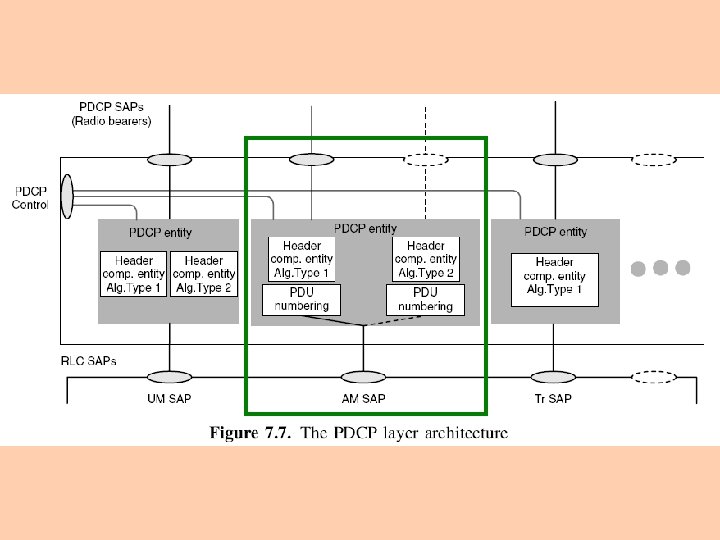
7. 5. 1 PDCP LAYER ARCHITECTURE Figure 7. 7 shows an example of PDCP layer architecture Multiplexing of Radio Bearers in PDCP layer is illustrated in Figure 7. 7 with two PDCP SAPs (one with dashed lines) provided by one PDCP entity using AM RLC
Every PDCP entity uses zero, one or several header compression algorithm types with a set of configurable parameters Several PDCP entities may use the same algorithm types The algorithm types and their parameters negotiated during RRC Radio Bearer establishment or reconfiguration procedures indicated to PDCP through PDCP Control Service Access Point (SAP)
7. 5. 2 PDCP FUNCTIONS Compression of redundant protocol control information (e. g. TCP/IP and RTP/UDP/IP headers) at the transmitting entity, and decompression at the receiving entity the header compression method is specific to the particular network layer, transport layer or upper layer protocol combinations, for example TCP/IP and RTP/UDP/IP the only compression method mentioned in PDCP Release’ 99 specification is RFC 2507
Transfer of user data PDCP receives a PDCP SDU and forwards it to the appropriate RLC entity and vice versa Support for lossless SRNS relocation those PDCP entities which are configured to support lossless SRNS relocation have PDU sequence numbers, which, together with unconfirmed PDCP packets are forwarded to the new SRNC during relocation only applicable when PDCP is using acknowledged mode RLC with in sequence delivery
7. 6 THE BROADCAST/MULTICAST CONTROL PROTOCOL Broadcast/Multicast Control (BMC) protocol service-specific Layer 2 protocol exists only in the user plane This protocol is designed to adapt broadcast and multicast services, originating from the Broadcast domain, on the radio interface
In Release’ 99 of the standard, the only service utilizing this protocol is SMS Cell Broadcast service This service is directly taken from GSM It utilizes UM RLC using CTCH (Common Traffic Channel) logical channel which is mapped into FACH transport channel
7. 6. 1 BMC Layer Architecture 7. 6. 2 BMC Functions
7. 6. 1 BMC LAYER ARCHITECTURE The BMC protocol, shown in Figure 7. 8, does not have any special logical architecture
7. 6. 2 BMC FUNCTIONS Storage of Cell Broadcast messages the BMC in RNC stores the Cell Broadcast messages received over the CBC–RNC interface for scheduled transmission CBC: Cell Broadcast Centre
Traffic volume monitoring and radio resource request for CBS on the UTRAN side, BMC calculates the required transmission rate for Cell Broadcast Service based on the messages received over CBC–RNC interface requests appropriate CTCH/FACH resources from RRC CTCH: Common Traffic Channel
Scheduling of BMC messages the BMC receives scheduling information together with each Cell Broadcast message over the CBC– RNC interface based on this scheduling information on the UTRAN side, BMC generates schedule messages schedules BMC message sequences
on the UE side, BMC evaluates the schedule messages indicates scheduling parameters to RRC, which are used by RRC to configure the lower layers for CBS reception
Transmission of BMC messages to UE this function transmits the BMC messages (Scheduling and Cell Broadcast messages) according to the schedule Delivery of Cell Broadcast messages to the upper layer this UE function delivers the received non-corrupted Cell Broadcast messages to the upper layer
7. 7 MULTIMEDIA BROADCAST MULTICAST SERVICE Multimedia Broadcast Multicast Service (MBMS) is being added to the standard in Release 6 The principle is similar to the CBS it enables transmission of content to multiple users in a point-to-multipoint manner The difference from CBS MBMS enables UTRAN also to control and monitor the users receiving the data, and thus enables charging for the content being delivered via MBMS
Applicability CBS has been used for low rate information, like sending cell location name etc. MBMS the mostly quoted data rate has been 64 kbps, which enables more sophisticated content to be distributed
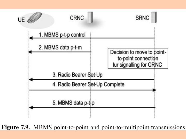
Depending on the number of users that have joined to receive the content via the MBMS, the network can select to use point-to-point transmission DCH is used as the transport channel point-to-multipoint transmission FACH is used as the transport channel in a particular cell for the MBMS content
On the physical layer DCH is mapped to DPDCH (Dedicated Physical Data channel) FACH is mapped to SCCPCH (Secondary Common Control Physical Channel) In the case of point-to-point connection the logical channel can be DCCH or DTCH with all the mapping in Release ’ 99 possible
In the case of point-to-multipoint case, there are two new logical channels MBMS point-to-multipoint Control Channel (MCCH), which carries the related control information MBMS point-to-multipoint Traffic Channel (MTCH), which carries the actual user data
UTRAN shall decide, based on the number of UEs in a particular cell which mode of MBMS operation to use, and if the situation changes, the network can transfer the UEs between different states of MBMS reception (Figure 7. 9)
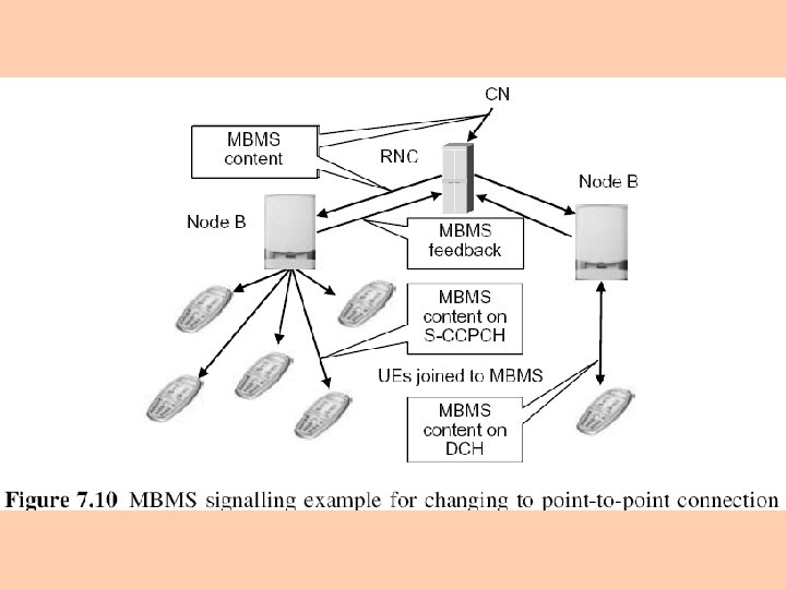
Figure 7. 10 shows an example scenario one cell uses point-to-multipoint while another cell has only one joined UE which is kept in the point-to-point state
7. 8 THE RADIO RESOURCE CONTROL PROTOCOL Radio Resource Control (RRC) messages the major part of the control signaling between UE and UTRAN carry all parameters required to set up, modify and release Layer 1 and Layer 2 protocol entities carry in their payload also all higher layer signaling MM (Mobility Management) CM (Connection Management) SM (Session Management)
The mobility of user equipment in the connected mode is controlled by RRC signaling, which are measurements handovers cell updates
7. 8. 1 RRC Layer Logical Architecture 7. 8. 2 RRC Service States 7. 8. 3 RRC Functions
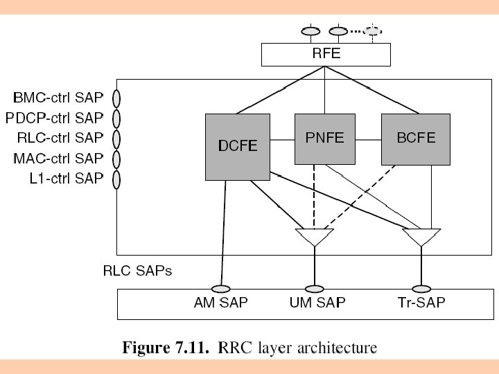
7. 8. 1 RRC LAYER LOGICAL ARCHITECTURE Figure 7. 11 shows the RRC layer logical architecture RRC layer has four functional entities 1. Dedicated Control Function Entity (DCFE) handles all functions and signaling specific to one UE in the SRNC there is one DCFE entity for each UE having an RRC connection with this RNC
DCFE uses mostly acknowledged mode RLC (AMSAP), but some messages are sent using unacknowledged mode SAP (e. g. RRC Connection Release) or transparent SAP (e. g. Cell Update) DCFE can utilize services from all Signaling Radio Bearers
2. Paging and Notification control Function Entity (PNFE) handles paging of idle mode UE(s) there is at least one PNFE in the RNC for each cell controlled by this RNC PNFE uses PCCH logical channel normally via transparent SAP of RLC PNFE could utilize also UM-SAP
In this example architecture the PNFE in RNC when receiving a paging message from an Iu interface needs to check with the DCFE whether or not this UE already has an RRC connection (signaling connection with another CN domain) if it does, the paging message is sent (by the DCFE) using the existing RRC connection
3. Broadcast Control Function Entity (BCFE) handles the system information broadcasting there is at least one BCFE for each cell in the RNC BCFE uses either BCCH or FACH logical channels, normally via transparent SAP BFCE could utilize also UM-SAP
4. Routing Function Entity (RFE) normally drawn outside of the RRC protocol and ‘logically’ belonging to the RRC layer, since the information required by this entity is part of RRC messages its task is the routing of higher layer messages to different MM/CM entities (UE side), or different core network domains (UTRAN side)
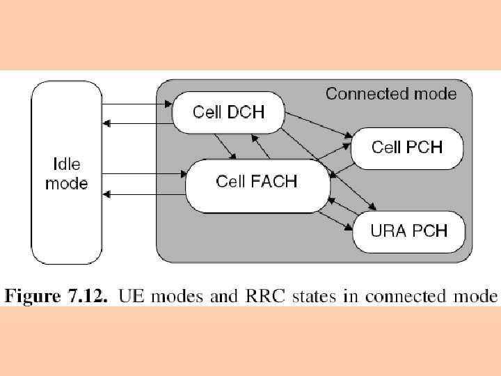
7. 8. 2 RRC SERVICE STATES Two basic operational modes of a UE idle mode connected mode Connected mode can be further divided into service states, which define what kind of physical channels a UE is using
Figure 7. 12 shows the main RRC service states in the connected mode the transitions between idle mode and connected mode the possible transitions within the connected mode
In the idle mode after a UE is switched on, it selects (either automatically or manually) a PLMN to contact the UE looks for a suitable cell of the chosen PLMN chooses that cell to provide available services, and tunes to its control channel this choosing is known as ‘camping on a cell’ after camping on a cell in idle mode the UE is able to receive system information and cell broadcast messages
the UE stays in idle mode until it transmits a request to establish an RRC connection in idle mode the UE is identified by identities such as IMSI, TMSI and P-TMSI (Packet-TMSI)
In the Cell_DCH state a dedicated physical channel is allocated to the UE is known by its serving RNC on a cell or active set level the UE performs measurements and sends measurement reports according to measurement control information received from RNC
In the Cell_FACH state no dedicated physical channel is allocated for the UE, but RACH and FACH channels are used instead, for transmitting both signaling messages and small amounts of user plane data the UE is also capable of listening to the broadcast channel (BCH) to acquire system information the UE performs cell reselections, and after a reselection always sends a Cell Update message to the RNC, so that the RNC knows the UE location on a cell level
for identification, a C-RNTI (Cell-Radio Network Temporary Identity) in the MAC PDU header separates UEs from each other in a cell when the UE performs cell reselection it uses the URNTI (UTRAN-Radio Network Temporary Identity) when sending the Cell Update message so that UTRAN can route the Cell Update message to the current serving RNC of the UE
In the Cell_PCH state the UE is still known on a cell level in SRNC, but it can be reached only via the paging channel (PCH) in this state the UE battery consumption is less than in the Cell-FACH state since the monitoring of the paging channel includes a discontinuous reception (DRX) functionality the UE also listens to system information on BCH
a UE supporting Cell Broadcast Service (CBS) is also capable of receiving BMC (Broadcast/ multicast control protocol) messages in this state if the UE performs a cell reselection it moves autonomously to the Cell-FACH state to execute the Cell Update procedure after which it re-enters the Cell-PCH state if no other activity is triggered during the Cell Update procedure
The URA_PCH state very similar to the Cell_PCH except that the UE does not execute Cell Update after each cell reselection, but instead reads UTRAN Registration Area (URA) identities from the broadcast channel only if the URA changes does UE inform its location to the SRNC this is achieved with the URA Update procedure, which is similar to the Cell Update procedure
When RRC connection is released or at RRC connection failure the UE leaves the connected mode and returns to idle mode
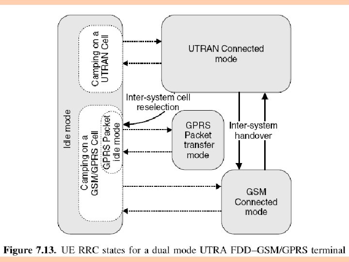
7. 8. 2. 1 ENHANCED STATE MODEL FOR MULTIMODE TERMINALS Figure 7. 13 an overview of the possible state transitions of a multimode (UTRA FDD–GSM/GPRS) terminal With these terminal types it is possible to perform inter-system handover between UTRA FDD and GSM inter-system cell reselection from UTRA FDD to GPRS
7. 8. 2. 2 EXAMPLE STATE TRANSITION CASES WITH PACKET DATA When sending or receiving reasonable amounts of data UE Once the data runs out and timers have elapsed UE will stay in Cell_DCH state will be moved away from Cell_DCH state Moving back to the Cell_DCH state always requires signaling between UE and SRNC the network sets up the necessary links to Node B
Use of Cell_DCH or Cell_FACH state is always a trade-off between terminal power consumption service delay signaling load network resource utilization
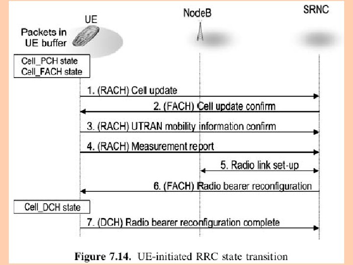
Figure 7. 14 shows the signaling flow of UE-initiated RRC state transition an application has created data to be transmitted to the network UE goes to Cell_FACH state sending data on RACH is not sufficient, a DCH needs to be set up
once in Cell_FACH state the UE initiates signaling on the RACH (1) after the network has received the measurement report on RACH (4) and a radio link has been set up between Node B and RNC (5) the reconfiguration message is sent on FACH to inform of the DCH parameters to be used (6)
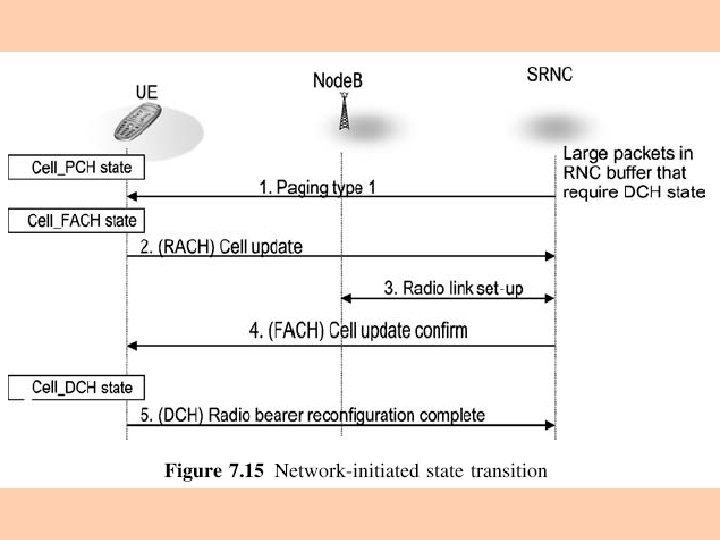
Figure 7. 15 shows the signaling flow of Networkinitiated RRC state transition the network-initiated RRC state change occurs when there is too much downlink data to be transmitted, and using FACH is not enough the network first transmits the paging message in the cell where the terminal is located (as the terminal location is known at cell level in Cell_PCH state) (1)
upon reception of the paging message, the terminal moves to Cell_FACH state and initiates signaling on the RACH (2) now there is no need for any measurement report as transition is initiated by the network the response from the terminal in the example case is a reconfiguration complete message (5), assuming the DCH parameters have been altered in connection to the state transition
7. 8. 3 RRC FUNCTIONS Establishment, maintenance and release of an RRC connection between UE and UTRAN Control of Radio Bearers, transport channels and physical channels Control of security functions (ciphering and integrity protection) Broadcast of system information, related to access stratum and non-access stratum
註: Access stratum the set of protocols and capabilities relevant to radio technique Non access stratum those technique which are independent of radio access network capabilities call and session control (set up, modify and release the transmission logic resources relevant to the required service) mobility control (enable the user to communicate regardless of his location)
Paging Initial cell selection and reselection in idle mode Integrity protection of signaling messages UE measurement reporting and control of the reporting RRC connection mobility functions Support of SRNS relocation
Support for downlink outer loop power control in the UE Open loop power control Cell broadcast service related functions Support for UE positioning functions