RADIO ACCESS NETWORK ARCHITECTURE 5 1 System Architecture


 interfaces with user and")
 operated by a single operator distinguished from each")
 the radio terminal used for")

 b) c) d) e) HLR (Home Location Register)")
 HLR (Home Location Register) a database located in user’s home system that stores")

 MSC/VLR (Mobile Services Switching Centre/Visitor Location Register) the switch (MSC) and database (VLR)")
 GMSC (Gateway MSC) the switch at the point where UMTS PLMN is connected")
 SGSN (Serving GPRS (General Packet Radio Service) Support Node) functionality is similar to")


 RNS a subnetwork")

 the network element responsible")
 messages the major part of the control")


 connects a mobile over a RAN")


 connection includes Signaling Radio Bearers and Traffic Radio Bearers")
 connection includes Iu Signaling Bearers and Iu")


 Main function of Node B perform the")


")


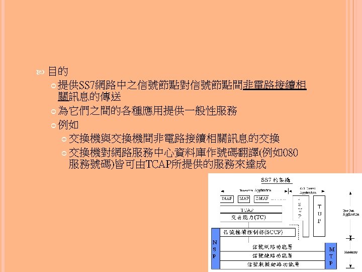
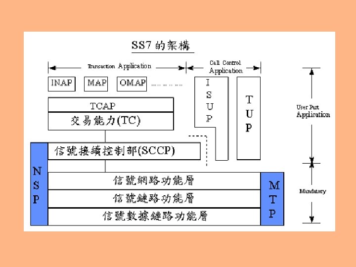
或稱交易能力應用 部(Transaction Capabilities Application Part;TCAP) 在SS 7網路中是屬於應用層(Application Layer)中的一個應 用服務元件(Application Service Element;ASE)")
 Service Specific Connection")


 AAL 0 no adaptation")


")
 management Iu release report unsuccessfully transmitted")

")

 management:combines all RAB handling RAB set-up modification of")


 speech frames, or the")


 provides the capability for Cell Broadcast Centre in")

 and the")
 AND THE RNSAP SIGNALLING 5. 5. 1.")


 for dedicated and shared")
 defines the structure of the data")


")


 list of Cells where dedicated and/or shared physical resources are")


![3. 3 Traffic Termination Point represents DCH, DSCH and USCH [TDD] data streams belonging](https://slidetodoc.com/presentation_image/4013bd35f6294123a5988202e6929240/image-138.jpg "3. 3 Traffic Termination Point represents DCH, DSCH and USCH [TDD] data streams belonging")
![3. 4 Iub RACH Data Port 3. 5 Iub CPCH Data Port [FDD] 3.](https://slidetodoc.com/presentation_image/4013bd35f6294123a5988202e6929240/image-139.jpg "3. 4 Iub RACH Data Port 3. 5 Iub CPCH Data Port [FDD] 3.")


 procedures used for the signaling that is not related to")


 is")


, including Visitor Location")
 covers similar")


 controls media stream")
 handle protocol conversions control a service coming via")
- Slides: 170
RADIO ACCESS NETWORK ARCHITECTURE
5. 1 System Architecture 5. 2 UTRAN Architecture 5. 3 General Protocol Model for UTRAN Terrestrial Interfaces 5. 4 Iu, The UTRAN–CN Interface 5. 5 UTRAN Internal Interfaces 5. 6 UTRAN Enhancements and Evolution 5. 7 UTRAN CN Architecture and Evolution
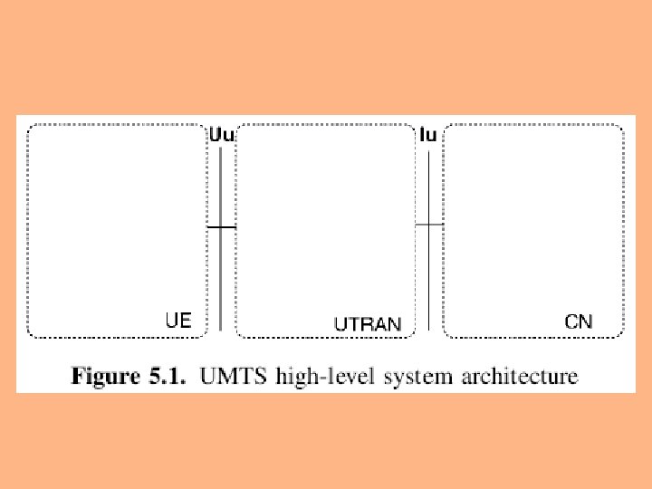
5. 1 SYSTEM ARCHITECTURE Functional network elements User Equipment (UE) interfaces with user and radio interface Radio Access Network (RAN, UMTS Terrestrial RAN = UTRAN) handles all radio-related functionality Core Network switches and routes calls and data connections to external networks
PLMN (Public Land Mobile Network) operated by a single operator distinguished from each other with unique identities operational either on their own or together with other sub-networks connected to other PLMNs as well as to other types of network, such as ISDN, PSTN, the Internet, etc.
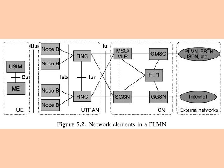
UE consists of two parts Mobile Equipment (ME) the radio terminal used for radio communication over Uu interface UMTS Subscriber Identity Module (USIM) a smartcard that holds the subscriber identity performs authentication algorithms stores authentication and encryption keys some subscription information that is needed at the terminal
UTRAN consists of two elements Node B converts data flow between Iub and Uu interfaces participates in radio resource management Radio Network Controller (RNC) owns and controls radio resources in its domain the service access point (SAP) for all services that UTRAN provides the CN e. g. , management of connections to UE
Main elements of CN a) b) c) d) e) HLR (Home Location Register) MSC/VLR (Mobile Services Switching Centre/Visitor Location Register) GMSC (Gateway MSC) SGSN (Serving GPRS (General Packet Radio Service) Support Node) GGSN (Gateway GPRS Support Node)
(a) HLR (Home Location Register) a database located in user’s home system that stores the master copy of user’s service profile consists of, e. g. , information on allowed services, forbidden roaming areas supplementary service information such as status of call forwarding and the call forwarding number
it is created when a new user subscribes to the system, and remains stored as long as the subscription is active for the purpose of routing incoming transactions to UE (e. g. calls or short messages) HLR also stores the UE location on the level of MSC/VLR and/or SGSN
(b) MSC/VLR (Mobile Services Switching Centre/Visitor Location Register) the switch (MSC) and database (VLR) that serve the UE in its current location for Circuit Switched (CS) services ◦ the part of the network that is accessed via MSC/VLR is often referred to as CS domain ◦ MSC ◦ ◦ used to switch CS transactions VLR holds a copy of the visiting user’s service profile, as well as more precise information on the UE’s location within the serving system
(c) GMSC (Gateway MSC) the switch at the point where UMTS PLMN is connected to external CS networks all incoming and outgoing CS connections go through GMSC
(d) SGSN (Serving GPRS (General Packet Radio Service) Support Node) functionality is similar to that of MSC/VLR but is typically used for Packet Switched (PS) services the part of the network that is accessed via SGSN is often referred to as PS domain (e) GGSN (Gateway GPRS Support Node) functionality PS services is close to that of GMSC but is in relation to
External networks can be divided into two groups CS networks provide circuit-switched connections, like the existing telephony service ISDN and PSTN are examples of CS networks PS networks provide connections for packet data services Internet is one example of a PS network
Main open interfaces Cu interface the electrical interface between USIM smartcard and ME Uu interface the WCDMA radio interface the interface through which UE accesses the fixed part of the system the most important open interface in UMTS
Iu interface connects UTRAN to CN Iur allows soft handover between RNCs Iub interface connects a Node B and an RNC
5. 2 UTRAN ARCHITECTURE 5. 2. 1 Radio Network Controller 5. 2. 2 Node B (Base Station)
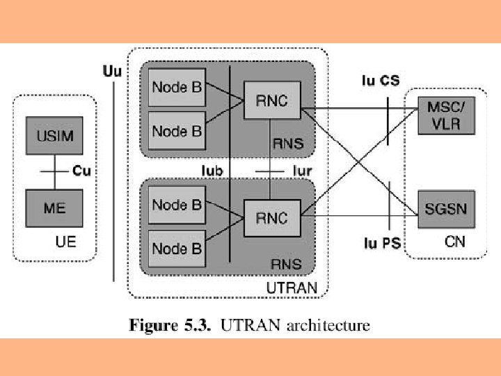
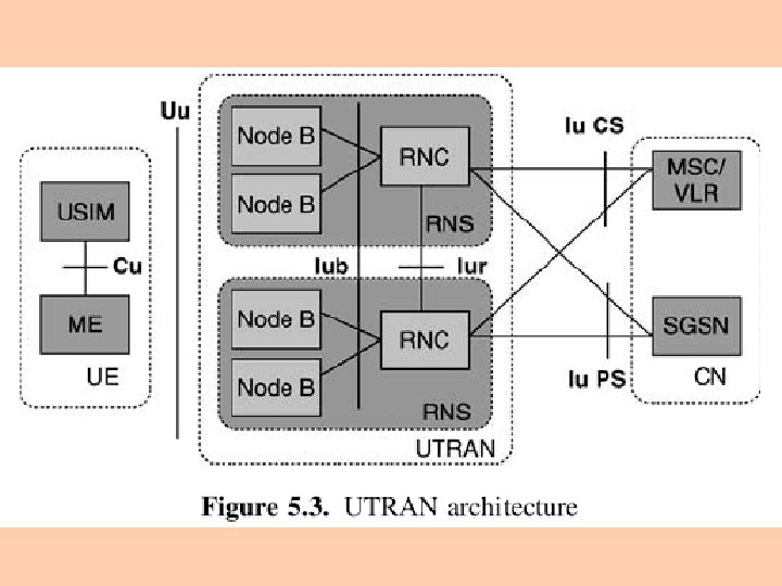
UTRAN consists of one or more Radio Network Sub-systems (RNS) RNS a subnetwork within UTRAN consists of one Radio Network Controller (RNC) and one or more Node Bs
RNCs may be connected to each other via Iur interface RNCs and Node Bs are connected with Iub interface Main characteristics of UTRAN support of UTRA and all related functionality support soft handover and WCDMA-specific Radio Resource Management algorithms use of ATM transport as the main transport mechanism in UTRAN use of IP-based transport as the alternative transport mechanism in UTRAN from Release 5 onwards
5. 2. 1 RADIO NETWORK CONTROLLER RNC (Radio Network Controller) the network element responsible for radio resources control of UTRAN it interfaces CN (normally to one MSC and one SGSN) terminates RRC (Radio Resource Control) protocol that defines the messages and procedures between mobile and UTRAN it logically corresponds to the GSM BSC
註:RADIO RESOURCE CONTROL Radio Resource Control (RRC) messages the major part of the control signaling between UE and UTRAN carry all parameters required to set up, modify and release Layer 2 and Layer 1 protocol entities The mobility of user equipment in the connected mode is controlled by RRC signaling measurements, handovers, cell updates, etc.
3 GPP BEARERS FOR SUPPORTING PACKET-SWITCHED SERVICES UTRAN CN
TRAFFIC BEARERS STRUCTURE SUPPORTING PACKET-SWITCHED SERVICES 3 GPP Bearer a dedicated path between mobile and its serving GGSN for a mobile to send or receive packets over a 3 GPP PS CN a 3 GPP Bearer in a UMTS network would be a UMTS Bearer
Constructed by concatenating Radio Access Bearer (RAB) connects a mobile over a RAN to the edge of CN (i. e. , a SGSN) CN Bearer carries user traffic between the edge of CN and a GGSN
SIGNALING AND TRAFFIC CONNECTIONS BETWEEN MOBILE AND SGSN
The signaling connection between mobile and SGSN is constructed by concatenating Signaling Radio Bearer between mobile and RAN (e. g. , the RNC in UTRAN) Iu Signaling Bearer between RAN and SGSN Signaling and traffic connections between mobile and SGSN Radio Resource Control (RRC) connection Radio Access Network Application Part (RANAP) connection
Radio Resource Control (RRC) connection includes Signaling Radio Bearers and Traffic Radio Bearers for the same mobile used to establish, maintain, and release Radio Bearers a mobile will use a common RRC connection to carry signaling and user traffic for both PS and CS services
Radio Access Network Application Part (RANAP) connection includes Iu Signaling Bearers and Iu Traffic Bearers for the same mobile used to establish, maintain, modify, change, and release all these Iu Bearers
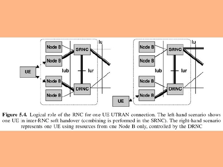
5. 2. 1. 1 LOGICAL ROLE OF THE RNC The RNC controlling one Node B is indicated as the Controlling RNC (CRNC) of Node B Controlling RNC responsible for load and congestion control of its own cells executes admission control for new radio links
In case one mobile–UTRAN connection uses resources from more than one RNS (due to handover), the RNCs involved have two separate logical roles Serving RNC (SRNC) Drift RNC (DRNC)
Serving RNC SRNC for one mobile is the RNC that terminates both the Iu link for the transport of user data and the corresponding RANAP (RAN Application Part) signaling to/from the core network SRNC also terminates the Radio Resource Control Signaling, that is the signaling protocol between the UE and UTRAN it performs L 2 processing of the data to/from the radio interface
basic Radio Resource Management operations are executed in SRNC map Radio Access Bearer (RAB) parameters into air interface transport channel parameters handover decision outer loop power control one UE connected to UTRAN has one and only one SRNC
Drift RNC DRNC is any RNC, other than the SRNC, that controls cells used by the mobile DRNC does not perform L 2 processing of the user plane data, but routes the data transparently between Iub and Iur interfaces one UE may have zero, one or more DRNCs
5. 2. 2 NODE B (BASE STATION) Main function of Node B perform the air interface L 1 processing, e. g. , channel coding and interleaving rate adaptation spreading also performs some basic Radio Resource Management operations, e. g. inner loop power control ◦ It logically corresponds to the GSM Base Station
註:INTERLEAVING The transmission of pulses from two or more digital sources in time-division sequence over a single path
5. 3 GENERAL PROTOCOL MODEL FOR UTRAN TERRESTRIAL INTERFACES 5. 3. 1 General 5. 3. 2 Horizontal Layers 5. 3. 3 Vertical Planes
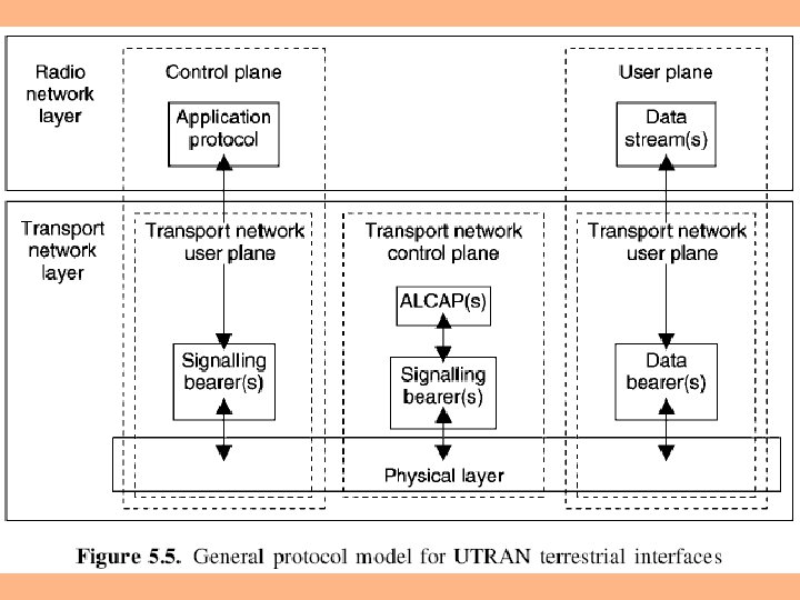
5. 3. 1 GENERAL The general protocol model for UTRAN terrestrial interfaces the layers and planes are logically independent of each other parts of the protocol structure may be changed in the future while other parts remain intact
5. 3. 2 HORIZONTAL LAYERS The protocol structure consists of two main layers Radio network layer Transport network layer
5. 3. 3 VERTICAL PLANES 5. 3. 3. 1 Control Plane 5. 3. 3. 2 User Plane 5. 3. 3. 3 Transport Network Control Plane 5. 3. 3. 4 Transport Network User Plane
5. 3. 3. 1 CONTROL PLANE Control Plane used for all UMTS-specific control signaling includes two parts application protocol RANAP (RAN application part) in Iu RNSAP (RNS application part) in Iur NBAP (Node B application part) in Iub signaling bearer transport the application protocol messages
Application protocol is used for setting up bearers to UE, i. e. radio access bearer in Iu radio link in Iur and Iub
5. 3. 3. 2 USER PLANE User Plane transport all information sent and received by the user, such as coded voice in a voice call packets in an Internet connection includes two parts data stream(s) data bearer(s) for data stream(s)
5. 3. 3. 3 TRANSPORT NETWORK CONTROL PLANE Used for all control signaling within transport layer Does not include any radio network layer information Includes ALCAP (Access Link Control Application Part) protocol used to set up the transport bearers (data bearer) for user plane
Includes signaling bearer needed for ALCAP Transport network control plane acts between control plane and user plane makes it possible for application protocol in radio network control plane to be completely independent of the technology selected for data bearer in user plane
5. 3. 3. 4 TRANSPORT NETWORK USER PLANE Transport Network User Plane data bearer(s) in user plane signaling bearer(s) for application protocol
5. 4 IU, THE UTRAN–CN INTERFACE 5. 4. 1 Protocol Structure for Iu CS 5. 4. 2 Protocol Structure for Iu PS 5. 4. 3 RANAP Protocol 5. 4. 4 Iu User Plane Protocol 5. 4. 5 Protocol Structure of Iu BC, and the SABP Protocol
Iu interface an open interface that divides the system into radiospecific UTRAN and CN handles switching, routing and service control
Iu can have two main different instances and one additional instance Iu CS connect UTRAN to Circuit Switched (CS) CN Iu PS connect UTRAN to Packet Switched (PS) CN Iu BC (Broadcast) support Cell Broadcast Services connect UTRAN to the Broadcast domain of CN
5. 4. 1 PROTOCOL STRUCTURE FOR IU CS 5. 4. 1. 1 Iu CS Control Plane Protocol Stack 5. 4. 1. 2 Iu CS Transport Network Control Plane Protocol Stack 5. 4. 1. 3 Iu CS User Plane Protocol Stack
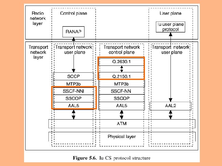
The following figure depicts the Iu CS overall protocol structure the three planes in the Iu interface share a common ATM (Asynchronous Transfer Mode) transport physical layer is the interface to physical medium optical fiber radio link copper cable
5. 4. 1. 1 IU CS CONTROL PLANE PROTOCOL STACK Control Plane protocol stack consists of RANAP, on top of Broadband (BB) SS 7 (Signaling System #7) protocols The applicable layers are Signaling Connection Control Part (SCCP) Message Transfer Part (MTP 3 -b) SAAL-NNI (Signaling ATM Adaptation Layer for Network to Network Interfaces)
TCAP 交易能力(Transaction Capabilities;TC)或稱交易能力應用 部(Transaction Capabilities Application Part;TCAP) 在SS 7網路中是屬於應用層(Application Layer)中的一個應 用服務元件(Application Service Element;ASE)
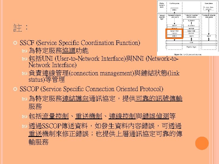
SAAL-NNI is further divided into Service Specific Coordination Function (SSCF) Service Specific Connection Oriented Protocol (SSCOP) ATM Adaptation Layer 5 (AAL) layers SSCF and SSCOP layers designed for signaling transport in ATM networks take care of signaling connection management AAL 5 is used for segmenting the data to ATM cells
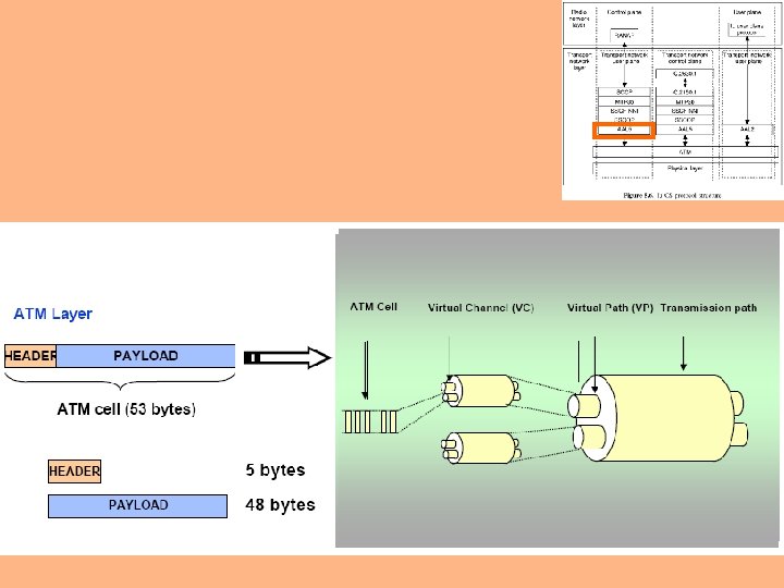
註:ATM IN BRIEF
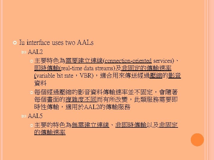
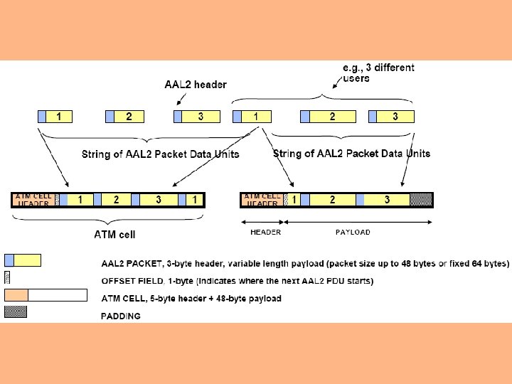
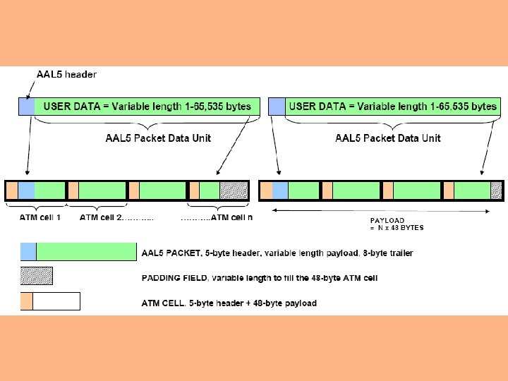
註:AAL 2 AND AAL 5 Above the ATM layer we usually find an ATM adaptation layer (AAL) AAL process the data from higher layers for ATM transmission segment the data into 48 -byte chunks and reassemble the original data frames on the receiving side
Five different AALs (0, 1, 2, 3/4, and 5) AAL 0 no adaptation is needed the other adaptation layers have different properties based on three parameters real-time requirements constant or variable bit rate connection-oriented or connectionless data transfer
5. 4. 1. 2 IU CS TRANSPORT NETWORK CONTROL PLANE PROTOCOL STACK Transport Network Control Plane protocol stack consists of Signaling Protocol on top of BB SS 7 protocols for setting up AAL 2 connections (Q. 2630. 1 [Q. aal 2 CS 1]) adaptation layer (Q. 2150. 1 [AAL 2 Signaling Transport Converter for MTP 3 b]) BB SS 7 are those described above without SCCP layer
5. 4. 1. 3 IU CS USER PLANE PROTOCOL STACK A dedicated AAL 2 connection is reserved for each individual CS service Iu User Plane Protocol residing directly on top of AAL 2
5. 4. 2 PROTOCOL STRUCTURE FOR IU PS 5. 4. 2. 1 Iu PS Control Plane Protocol Stack 5. 4. 2. 2 Iu PS Transport Network Control Plane Protocol Stack 5. 4. 2. 3 Iu PS User Plane Protocol Stack
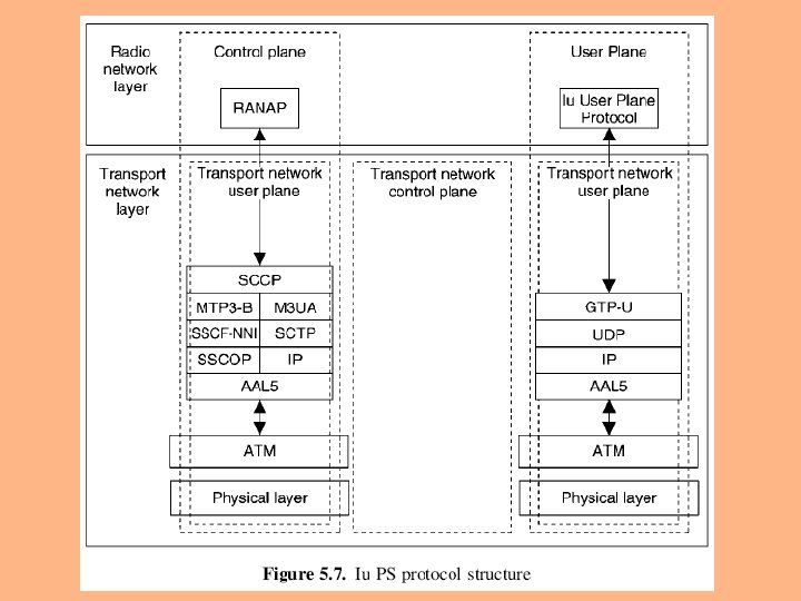
The following figure depicts Iu PS protocol structure a common ATM transport is applied for both User Plane and Control Plane the physical layer is as specified for Iu CS
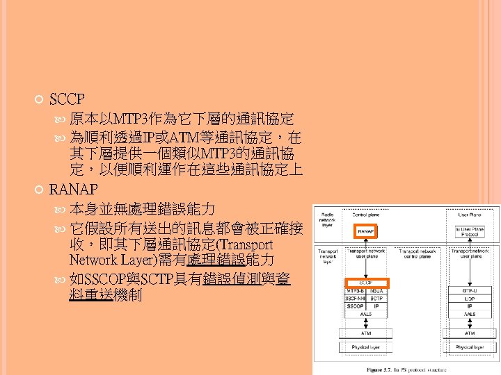
5. 4. 2. 1 IU PS CONTROL PLANE PROTOCOL STACK Control Plane protocol stack consists of RANAP signaling bearers BB SS 7 -based signaling bearer an alternative IP-based signaling bearer SCCP layer is used for both bearer
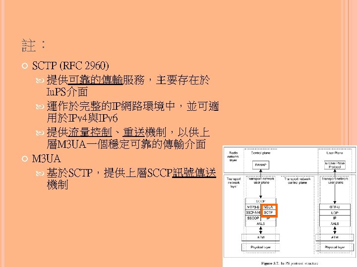
IP-based signaling bearer consists of M 3 UA (SS 7 MTP 3 – User Adaptation Layer) SCTP (Stream Control Transmission Protocol) designed for signaling transport in the Internet ensure reliable, in-sequence transport of messages with congestion control IP (Internet Protocol) AAL 5 (common to both alternatives)
5. 4. 2. 2 IU PS TRANSPORT NETWORK CONTROL PLANE PROTOCOL STACK Transport Network Control Plane is not applied to Iu PS Setting up of GTP tunnel requires an identifier for the tunnel and IP addresses for both directions these are already included in RANAP RAB Assignment messages
5. 4. 2. 3 IU PS USER PLANE PROTOCOL STACK Iu PS User Plane multiple packet data flows are multiplexed on one or several AAL 5 PVCs (Permanent Virtual Circuit) GTP-U (User Plane part of GPRS Tunneling Protocol) is the multiplexing layer that provides identities for individual packet data flow each flow uses UDP connectionless transport and IP addressing
5. 4. 3 RANAP PROTOCOL RANAP defines interactions between RNS and CN the signaling protocol in Iu that contains all the control information specified for Radio Network Layer implemented by various RANAP Elementary Procedures (EP) each RANAP function may require execution of one or more EPs
three classes of EP class 1 EP request and response (failure or success) class 2 EP request without response class 3 EP request and possibility for one or more responses
RANAP functions relocation RAB (Radio Access Bearer) management Iu release report unsuccessfully transmitted data common ID management paging
management of tracing UE–CN signaling transfer security mode control management of overload reset location reporting
RANAP FUNCTION- Relocation:handles both SRNS relocation and hard handover (including inter-system case to/from GSM) SRNS relocation the serving RNS functionality is relocated from one RNS to another without changing the radio resources and without interrupting the user data flow prerequisite:all Radio Links are already in the same DRNC that is the target for the relocation
Inter-RNS hard handover relocate the serving RNS functionality from one RNS to another and to change the radio resources correspondingly by a hard handover in Uu interface prerequisite:UE is at the border of the source and target cells
RANAP FUNCTION- RAB (Radio Access Bearer) management:combines all RAB handling RAB set-up modification of the characteristics of an existing RAB clearing an existing RAB Iu releases all resources (Signaling link and U-Plane) from a given instance of Iu related to the specified UE
RANAP FUNCTION- Reporting unsuccessfully transmitted data allows CN to update its charging records with information from UTRAN if part of the data sent was not successfully sent to UE Common ID management the permanent identification of the UE is sent from CN to UTRAN to allow paging coordination from possibly two different CN domains
RANAP FUNCTION- Paging used by CN to page an idle UE for a UE terminating service request, such as a voice call a paging message is sent from CN to UTRAN with the UE common identification (permanent Id) and the paging area UTRAN will either use an existing signaling connection, if one exists, to send the page to UE or broadcast the paging in the requested area
RANAP FUNCTION- Management of tracing CN may, for operation and maintenance purposes, request UTRAN to start recording all activity related to a specific UE–UTRAN connection
RANAP FUNCTION- UE–CN signaling transfer of the first UE message from UE to UTRAN example a response to paging a request of a UE-originated call a registration to a new area it also initiates the signaling connection for Iu direct transfer used for carrying all consecutive signaling messages over the Iu signaling connection in both uplink and downlink directions
RANAP FUNCTION- Security mode control used to set the ciphering or integrity checking on or off when ciphering is on the signaling and user data connections in the radio interface are encrypted with a secret key algorithm
when integrity checking is on an integrity checksum, further secured with a secret key, is added to some or all of the Radio Interface signaling messages this ensures that the communication partner has not changed, and the content of the information has not been altered
RANAP FUNCTION- Management of overload control the load over Iu interface against overload due example, to process overload at the CN or UTRAN a simple mechanism is applied that allows stepwise reduction of the load and its stepwise resumption [(中斷後的)重新開始], triggered by a timer
RANAP FUNCTION- Reset reset the CN or the UTRAN side of Iu interface in error situations one end of the Iu may indicate to the other end that it is recovering from a restart, and the other end can remove all previously established connections
RANAP FUNCTION- Location reporting allows CN to receive information on the location of a given UE includes two elementary procedures control the location reporting in RNC send the actual report to CN
5. 4. 4 IU USER PLANE PROTOCOL Iu User Plane protocol in the Radio Network Layer of Iu User Plane defined to be independent of CN domain purpose carry user data related to RABs over Iu interface the protocol performs either a fully transparent operation, or framing for user data segments the protocol also performs some basic control signaling to be used for initialization and online control
the protocol has two modes transparent mode 本身並不會加入任何協定檔頭,亦即上層所傳送的 通訊協定會直接加上GTP-U檔頭後送出,Iu FP本身 並不加入任何資料 applied for RABs that assume fully transparent operation support mode 所提供的傳輸協定,包含速率控制與時間限制,可 用於支援real-time的語音傳輸 for predefined SDU (Service Data Unit) sizes performs framing of user data into segments of predefined size
the SDU sizes typically correspond to AMR (Adaptive Multirate Codec) speech frames, or the frame sizes derived from the data rate of a CS data call control procedures for initialization and rate control are defined, and a functionality is specified for indicating the quality of the frame based, for example, on CRC from radio interface
5. 4. 5 PROTOCOL STRUCTURE OF IU BC, AND THE SABP PROTOCOL Iu BC interface connects RNC in UTRAN with the broadcast domain of Core Network, namely with Cell Broadcast Centre used to define Cell Broadcast information that is transmitted to mobile user via Cell Broadcast Service e. g. name of city/region visualized on the mobile phone display
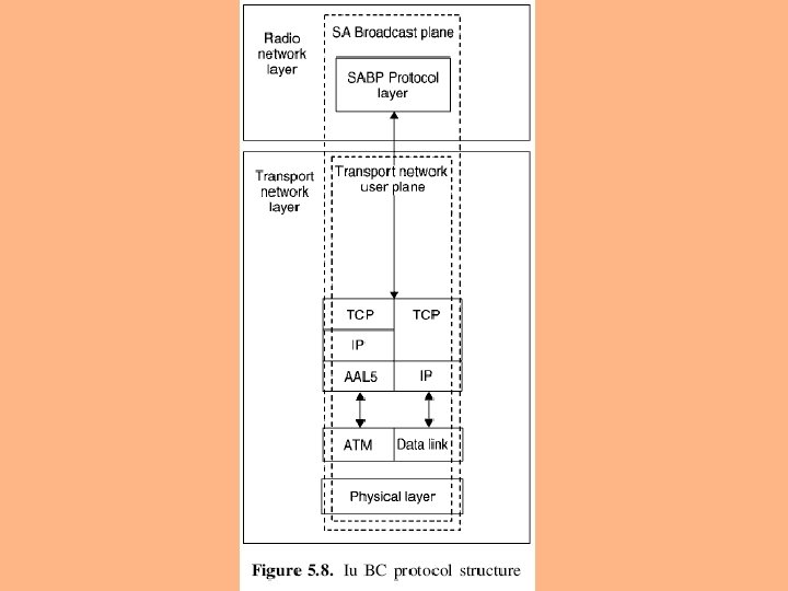
Iu BC is a control plane only interface the protocol structure of Iu BC is shown as follows
SABP (Service Area Broadcast Protocol) provides the capability for Cell Broadcast Centre in CN to define, modify and remove cell broadcast messages from RNC SABP has the following functions message handling broadcast of new messages amendment [修正] of existing broadcast messages prevention of broadcasting of specific messages
load handling responsible for determining the loading of the broadcast channels at any particular point in time reset permits CBC to end broadcasting in one or more Service Areas
5. 5 UTRAN INTERNAL INTERFACES 5. 5. 1 RNC–RNC Interface (Iur Interface) and the RNSAP Signaling 5. 5. 2 RNC–Node B Interface and the NBAP Signaling
5. 5. 1 RNC–RNC INTERFACE (IUR INTERFACE) AND THE RNSAP SIGNALLING 5. 5. 1. 1 Iur 1:Support of the Basic Inter-RNC Mobility 5. 5. 1. 2 Iur 2:Support of Dedicated Channel Traffic 5. 5. 1. 3 Iur 3:Support of Common Channel Traffic 5. 5. 1. 4 Iur 4:Support of Global Resource Management
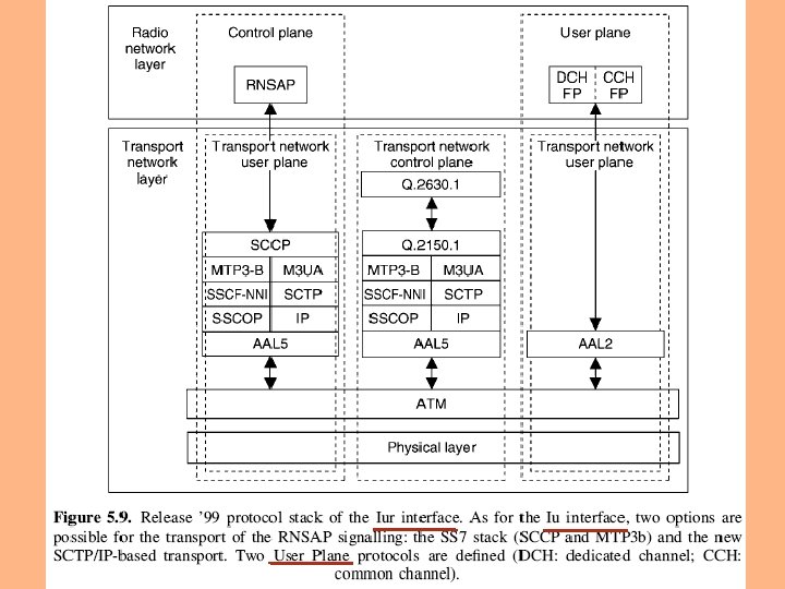
The following figure shows the protocol stack of RNC to RNC interface (Iur interface) Iur interface provides four distinct functions support of basic inter-RNC mobility (Iur 1) support of dedicated channel traffic (Iur 2) support of common channel traffic (Iur 3) support of global resource management (Iur 4)
5. 5. 1. 1 IUR 1:SUPPORT OF THE BASIC INTER-RNC MOBILITY This functionality requires the basic module of RNSAP signaling provides the functionality needed for the mobility of the user between two RNCs does not support the exchange of any user data traffic
If this module is not implemented the only way for a user connected to UTRAN via RNS 1 to utilize a cell in RNS 2 is to disconnect itself temporarily from UTRAN (release the RRC connection) The functions offered by Iur basic module include support of SRNC relocation support of inter-RNC cell and UTRAN registration area update support of inter-RNC packet paging reporting of protocol errors
Since this functionality does not involve user data traffic across Iur User Plane and Transport Network Control Plane protocols are not needed
5. 5. 1. 2 IUR 2:SUPPORT OF DEDICATED CHANNEL TRAFFIC This functionality requires dedicated channel module of RNSAP signaling allows dedicated and shared channel traffic between two RNCs
This functionality requires also User Plane Frame Protocol (FP) for dedicated and shared channel Transport Network Control Plane protocol (Q. 2630. 1 [Q. aal 2 CS 1]) used for the set-up of transport connections (AAL 2 connections)
Frame Protocol for dedicated channels (DCH FP) defines the structure of the data frames carrying the user data the control frames used to exchange measurements and control information Frame Protocol for common channels (CCH FP) describes the User plane procedure for the shared channel
The functions offered by Iur DCH module establishment, modification and release of the dedicated and shared channel in DRNC due to handovers in dedicated channel state set-up and release of dedicated transport connections across Iur interface transfer of DCH Transport Blocks between SRNC and DRNC management of the radio links in DRNS via dedicated measurement report procedures power setting procedures compress mode control procedures
5. 5. 1. 3 IUR 3:SUPPORT OF COMMON CHANNEL TRAFFIC This functionality allows the handling of common channel (i. e. RACH, FACH and CPCH) data streams across Iur interface Note CPCH:Common Packet CHannel RACH:Random Access CHannel FACH:Forward Access CHannel
It requires Common Transport Channel module of RNSAP protocol Iur Common Transport Channel Frame Protocol (CCH FP) If signaled AAL 2 connections are used Q. 2630. 1 [Q. aal 2 CS 1] signaling protocol of the Transport Network Control Plane is needed
The functions offered by Iur common transport channel module set-up and release of the transport connection across Iur for common channel data streams splitting of the MAC layer between SRNC (MAC-d) and DRNC (MAC-c) flow control between MAC-d and MAC-c
5. 5. 1. 4 IUR 4:SUPPORT OF GLOBAL RESOURCE MANAGEMENT This provides signaling to support enhanced radio resource management and O&M features across Iur interface The function is considered optional This function has been introduced in subsequent releases for the support of common radio resource management between RNCs advanced positioning methods Iur optimization
The functions offered by Iur global resource module transfer of cell information and measurements between two RNCs transfer of positioning parameters between controller transfer of Node B timing information between two RNCs
5. 5. 2 RNC–NODE B INTERFACE AND THE NBAP SIGNALING 5. 5. 2. 1 Common NBAP and the Logical O&M 5. 5. 2. 2 Dedicated NBAP
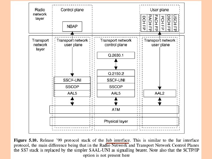
Figure 5. 10 shows the protocol stack of RNC–Node B interface (Iub interface)
Figure 5. 11 shows the logical model of Node B seen from the controlling RNC
Figure 5. 11 Logical Model of Node B
Logical model of Node B includes the logical resources provided by Node B to UTRAN (via Controlling RNC) - depicted as "cells" which include the following physical channel resources DPCH (Dedicated Physical Channel) PDSCH (Physical Downlink Shared Channel) PUSCH (Physical Uplink Shared Channel) the dedicated channels which have been established on Node B the common transport channels that Node B provides to RNC
Elements of the logical model Node B Communication Contexts for dedicated and shared channels 1. corresponds to all the dedicated resources that are necessary for a user in dedicated mode and using dedicated and/or shared channels as restricted to a given Node B
attributes (not exhaustive) list of Cells where dedicated and/or shared physical resources are used list of DCH which are mapped on the dedicated physical resources for that Node B Communication Context list of DSCH and USCH [TDD] which are used by the respective UE
the complete DCH characteristics for each DCH, identified by its DCH-identifier the complete Transport Channel characteristics for each DSCH and USCH, identified by its Shared Channel identifier list of Iub DCH Data Ports list of Iub DSCH Data ports and Iub USCH data ports FDD – up to one Iub TFCI 2 Data Port
for each Iub DCH Data Port, the corresponding DCH and cells which are carried on this data port for each Iub DSCH and USCH data port, the corresponding DSCH or USCH and cells which serve that DSCH or USCH physical layer parameters (outer loop power control, etc)
2. Common Transport Channel configured in Node B, on request of CRNC attributes (not exhaustive) Type (RACH, CPCH [FDD], FACH, DSCH, USCH [TDD], PCH) Associated Iub RACH Data Port for a RACH, Iub CPCH Data Port for a CPCH [FDD], Iub FACH Data Port for a FACH, Iub PCH Data Port for PCH Physical parameters
3. Transport network logical resources 3. 1 Node B Control Port Functionality exchange the signaling information for the logical O&M of Node B the creation of Node B Communication Contexts
the configuration of the common transport channels that Node B provides in a given cell PCH and BCH control information between the RNC and the Node B Control Port corresponds to one signaling bearer between the controlling RNC and the Node B There is one Node B Control Port per Node B
3. 2 Communication Control Port used to send the procedures for controlling the connections between radio links and Iub DCH data ports from RNC to Node B for control of Node B Communication Contexts one signaling bearer between RNC and Node B can at most correspond to one Communication Control Port Node B may have multiple Communication Control Ports (one per Traffic Termination Point)
3. 3 Traffic Termination Point represents DCH, DSCH and USCH [TDD] data streams belonging to one or more Node B Communication Contexts (UE contexts), which are controlled via one Communication Control Port
3. 4 Iub RACH Data Port 3. 5 Iub CPCH Data Port [FDD] 3. 6 Iub FACH Data Port 3. 7 Iub PCH Data Port 3. 8 Iub FDD TFCI 2 Data Port 3. 9 Iub DSCH Data Port 3. 10 Iub TDD USCH Data Port 3. 11 Iub DCH Data Port
5. 5. 2. 1 COMMON NBAP AND THE LOGICAL O&M Iub interface signaling (NBAP, Node B Application Part) is divided into two essential components common NBAP defines the signaling procedures across the common signaling link dedicated NBAP used in the dedicated signaling link
User Plane Iub frame protocols define the structures of the frames the basic inband control procedures for every type of transport channel (i. e. for every type of data port of the model) Q. 2630. 1 [Q. aal 2 CS 1] signaling used for dynamic management of AAL 2 connections used in User Plane
Common NBAP (C-NBAP) procedures used for the signaling that is not related to one specific UE context already existing in Node B defines all the procedures for the logical O&M (Operation and Maintenance) of Node B such as configuration and fault management
Main functions of Common NBAP set-up of the first radio link of one UE, and selection of the traffic termination point cell configuration handling of the RACH/FACH/CPCH and PCH channels initialization and reporting of Cell or Node B specific measurement Location Measurement Unit (LMU) control fault management
5. 5. 2. 2 DEDICATED NBAP When the RNC requests the first radio link for one UE via C-NBAP Radio Link Set-up procedure Node B assigns a traffic termination point for the handling of this UE context every subsequent signaling related to this mobile is exchanged with dedicated NBAP (D-NBAP) procedures across the dedicated control port of the given Traffic Termination Point
Main functions of the Dedicated NBAP addition, release and reconfiguration of radio links for one UE context handling of dedicated and shared channels handling of softer combining initialization and reporting of radio link specific measurement radio link fault management
5. 6 UTRAN ENHANCEMENTS AND EVOLUTION 5. 6. 1 IP Transport in UTRAN 5. 6. 2 Iu Flex 5. 6. 3 Stand Alone SMLC and Iupc Interface 5. 6. 4 Interworking between GERAN and UTRAN, and the Iur-g Interface
Release’ 99 UTRAN architecture defines the basic set of network elements and interface protocols for the support of Release ’ 99 WCDMA radio interface Enhancement of the Release’ 99 UTRAN architecture support new WCDMA radio interface features to provide a more efficient, scalable and robust 3 GPP system architecture Four most significant additions to the UTRAN architecture introduced in Release 5 are described in the subsequent sections
5. 6. 1 IP TRANSPORT IN UTRAN ATM the transport technology used in the first release of UTRAN IP transport introduced in Release 5 In addition to the initially defined option of AAL 2/ATM, user plane FP frames can also be conveyed over UDP/IP protocols on Iur/Iub over RTP/UDP/IP protocols in Iu CS interface
5. 6. 2 IU FLEX Release’ 99 architecture presented in Figure 5. 3 only one MSC and one SGSN connected to RNC i. e. only one Iu PS and Iu CS interface in the RNC Iu flex (flexible) allows one RNC to have more than one Iu PS and Iu CS interface instances with the core Main benefits of this feature possible load sharing between core network nodes
5. 6. 3 STAND ALONE SMLC AND IUPC INTERFACE Location-based services expected to be a very important source of revenue for mobile operators a number of different applications are expected to be available and largely used UTRAN architecture includes a stand alone Serving Mobile Location Centre (stand alone SMLC, or, simply, SAS) a new network element for handling of positioning measurements and calculation of the mobile station position
SAS connected to RNC via Iupc interface Positioning Calculation Application Part (PCAP) is the L 3 protocol used for RNC-SAS signaling SAS performs the following procedures provides positioning (GPS related) data to RNC performs the position calculation function for UE assisted GPS
SAS and Iupc interface are optional elements Iupc the first version, supported only Assisted GPS later versions, support for other positioning methods
5. 6. 4 INTERWORKING BETWEEN GERAN AND UTRAN, AND THE IUR-G INTERFACE Iu interface scheduled to be part of the GSM/EDGE Radio Access Network (GERAN) in GERAN Release 5 allows reusing 3 G Core Network also for GSM/EDGE radio interface (and frequency band), but also allows a more optimized interworking between the two radio technologies
Effect RNSAP basic mobility module is enhanced to allow the mobility to and from GERAN cells in the target and the source RNSAP global module is enhanced in order to allow GERAN cells measurements to be exchanged between controllers allows a Common Radio Resource Management (CRRM) between UTRAN and GERAN radios
Iur-g interface refer to the above-mentioned set of Iur functionalities that are utilized also by GERAN
5. 7 UMTS CORE NETWORK ARCHITECTURE AND EVOLUTION 5. 7. 1 Release’ 99 Core Network Elements 5. 7. 2 Release 5 Core Network and IP Multimedia Sub -system
UMTS radio interface, WCDMA a bigger step in radio access evolution from GSM networks UMTS core network did not experience major changes in 3 GPP Release’ 99 specification Release’ 99 structure was inherited from GSM core network both UTRAN and GERAN based radio access network connect to the same core network
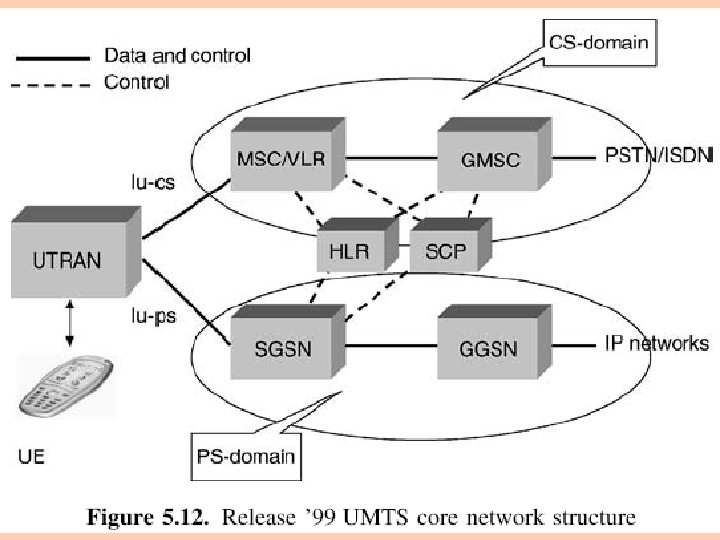
5. 7. 1 RELEASE ’ 99 CORE NETWORK ELEMENTS Two domains of Release’ 99 core network Circuit Switched (CS) domain Packet Switched (PS) domain The division comes from the different requirements for data depending on whether it is real time (circuit switched) or non-real time (packet data)
Figure 5. 12 Release’ 99 core network structure with both CS and PS domains Registers HLR, VLR, EIR Service Control Point (SCP) the link for providing a particular service to end user
CS domain has the following elements Mobile Switching Centre (MSC), including Visitor Location Register (VLR) Gateway MSC (GMSC)
PS domain has the following elements Serving GPRS Support Node (SGSN) covers similar functions as MSC for packet data, including VLR type functionality Gateway GPRS Support Node (GGSN) connects PS core network to other networks, e. g. to the Internet
In addition to the two domains, the network needs various registers for properation Home Location Register (HLR) Equipment Identity Register (EIR) contains the information related to the terminal equipment can be used to, e. g. , prevent a specific terminal from accessing the network
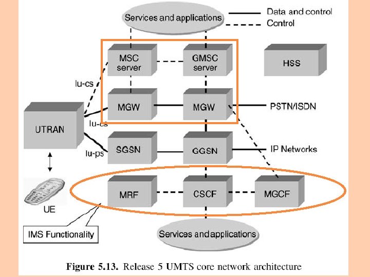
5. 7. 2 RELEASE 5 CORE NETWORK AND IP MULTIMEDIA SUB-SYSTEM Release 4 included the change in core network CS domain MSC was divided into MSC server and Media Gateway (MGW) GMSC was divided into GMSC server and MGW Release 5 contains the first phase of IP Multimedia Sub-system (IMS) this will enable a standardized approach for IP-based service provision via PS domain
Release 6 enhance IMS to allow the provision of services similar to CS domain services from PS domain Release 5 architecture is presented in Figure 5. 13 Home Subscriber Server (HSS) shown as an independent item Session Initiation Protocol (SIP) the key protocol between terminal and IMS the basis for IMS-related signaling
MSC or GMSC server takes care of the control functionality as MSC or GMSC, respectively user data goes via Media Gateway (MGW) one MSC/GMCS server can control multiple MGWs this allows better scalability of the network when data rates increase with new data services in this case, only the number of MGWs needs to be increased MGW performs actual switching for user data and network interworking processing e. g. , echo cancellation or speech decoding/ encoding
IMS includes the following key elements Media Resource Function (MRF) controls media stream resources or mixes different media streams Call Session Control Function (CSCF) the first contact point to terminal in the IMS (as a proxy) handling of session states acting as a firewall towards other operator’s networks
Media Gateway Control Function (MGCF) handle protocol conversions control a service coming via CS domain and perform processing in an MGW, e. g. for echo cancellation