RADIATIVE HEAT TRANSFER Thermal radiation is the electromagnetic


- Slides: 93

RADIATIVE HEAT TRANSFER Thermal radiation is the electromagnetic radiation emitted by a body as a result of its temperature. There are many types of electromagnetic radiation; thermal is only one of them. It propagated at the speed of light, 3× 10⁸ m/s. The wavelength of thermal radiation lies in the range from 0. 1 to 100 µm, Visible light has wavelength from 0. 4 to 0. 7 µm.

RADIATIVE HEAT TRANSFER (2) The sun with an effective surface temperature of 5760 K emits most of its at the extreme lower end of the spectrum 0. 1 to 4 µm (µm = 10 -6 m). The radiations from a lamp filament are in the range of 1 to 10 µm. Most solids and liquids have a continuous spectrum; they emit radiations pf all wavelengths.

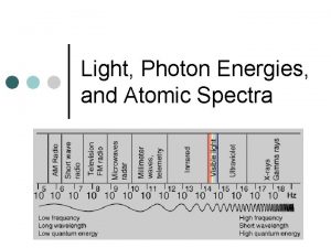
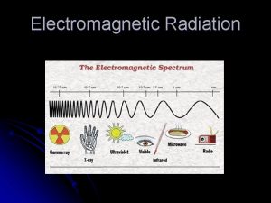
Spectrum of Electromagnetic Wave

RADIATIVE HEAT TRANSFER (3) Gases and vapours radiate energy only at certain bands of wavelength and hence are called selective emitters. The emission of thermal radiation depends upon the nature, temperature and state of the emitting surface. However with gases the dependence is also upon the thickness of the emitting layer and the gas pressure.

Absorptivity, Reflectivity and Transmissivity The total radiant energy (Q 0) impinging upon a body be (1) partially or totally absorbed by it (Qa), (2) reflected from its surface (Qr) or (3) transmitted through it (Qt) in accordance with the characteristics of the body.

Absorptivity, Reflectivity and Transmissivity (contd. ) α absorptivity ρ reflectivity The values of these quantities depend upon the nature of the surface of the bodies, its temperature and wavelength of incident rays.

BLACK BODY For black body, α = 1, ρ = 0, τ =0 Snow is nearly black to thermal radiations. α = 0. 985 The absorptivity of surfaces can be increased to 90 -95% by coating their surfaces with lamp black or dark range paint. In actual practice, there does not exist a perfectly black body that will absorb all the incident radiations.

GRAY BODY A gray body has the absorptivity less than unity, Absorptivity remains constant over the range of temperature and wavelength of incident radiation. For a real body, it does not satisfy the condition of constant. So Gray body is a concept only.

Specular body and absolutely white body A body that reflects all the incident thermal radiations is called a specular body (if reflection is regular) or an absolutely white body (if the reflection is diffused). For such bodies, ρ = 1, α = 0, τ =0

Reflections θ θ Specular Reflection θ Diffuse Reflection

Transparent or Diathermaneous. A body that allows all the incident radiations to pass through it is called transparent or diathermaneous. For such bodies, ρ = 0, α = 0, τ =1 Transmissivity varies with wavelength of incident radiation. A material may be transparent for certain wavelengths and nontransparent for other wavelengths. A thin glass plate transmits most of thermal radiations from sun, but absorbs in equally great measure thermal radiations emitted from the low temperature interior of a building.

Spectral and Spatial Distribution Magnitude of radiation at any wavelength (monochromatic) and spectral distribution are found to vary with nature and temperature of the emitting surface. A surface element emits radiation in all directions; the intensity of radiation is however different in different directions.

Radiant Energy Distribution (E )b Spectral Distribution Spatial Distribution

BLACK BODY RADIATION The energy emitted by a black surface varies with (i) wavelength, (ii) temperature and (iii) surface characteristics of a body. For a given wavelength, the body radiates more energy at elevated temperatures. Based on experimental evidence, Planck suggested the following law for the spectral distribution of emissive power for a fixed temperature.

Planck ‘s Law (1)

Symbols where h = Planck’s constant, 6. 6256 10 -34 J-s C = Velocity of light in vacuum, 2. 998 108 m/s K = Boltzman constant, 13. 802 10 -24 J/K = wavelength of radiation waves, m T = absolute temperature of black body, K

Simplification Equation (1) may be written as where Wm 2 m. K

SPECTRAL ENERGY DISTRIBUTION (E )b denotes monochromatic (single wavelength) emissive power and is defined as the energy emitted by the black surface (in all directions) at a given wavelength per unit wavelength interval around . The rate of energy emission in the interval d = (E )bd . The variation of distribution of monochromatic emission power with wavelength is called the spectral energy distribution.

SPECTRAL ENERGY DISTRIBUTION Graph

Features of Spectral Energy Distribution The monochromatic emissive power varies across the wavelength spectrum, the distribution is continuous, but nonuniform. The emitted radiation is practically zero at zero wavelength. With increase in wavelength, the monochromatic emissive power increases and attains a certain maximum value. With further increase in wavelength, the emissive power drops again to almost zero value at infinite wavelength. At any wavelength the magnitude of the emitted radiation increases with increasing temperature The wavelength at which the monochromatic emissive power is maximum shifts in the direction of shorter wavelengths as the

TOTAL EMISSIVE POWER At any temperature, the rate of total radiant energy emitted by a black body is given by The above integral measures the total area under the monochromatic emissive power versus wavelength curve for the black body, and it represents the total emissive power per unit area (radiant energy flux density) radiated from a black body.

Wien’s Law. For shorter wavelength, is very large and Then Planck’s law reduces to which is called Wien’s law.

Rayleigh-Jean’s Law For longer wavelengths is very small and hence we can write So, Planck’s distribution law becomes This identity is called Rayleigh-Jean’s Law.

Stefan- Boltzman Law The total emissive power E of a surface is defined as the total radiant energy emitted by the surface in all directions over the entire wavelength range per unit surface area per unit time. The amount of radiant energy emitted per unit time from unit area of black surface is proportional to the fourth power of its absolute temperature. is the radiation coefficient of black body.

SOME DERIVATION Let As and as

SOME DERIVATION, contd. expanding

SOME DERIVATION, contd. 2 We have or, where W/m 2 K 2, Stefan-Boltzman constant If there are two bodies, the net radiant heat flux is given by

Wien’s Displacement Law The wavelength associated with maximum rate of emission depends upon the absolute temperature of the radiating surface. For maximum rate of emission,

Simplification The above equation is solved by trial and error method to get

For Maximum Emission m. K denotes the wavelength at which emissive power is maximum Statement of Wein’s Displacement law The product of the absolute temperature and the wavelength, at which the emissive power is maximum, is constant. Wein’s displacement law finds application in the prediction of a very high temperature through measurement of wavelength.

Maximum Monochromatic Emissive Power for a Black Body Combining Planck’s law and Wien’s displacement law

Kirchoff’s Law Fig Radiant Heat exchange between black and non- black surfaces

Kirchoff’s Law The surfaces are arranged parallel and so close to each other so that the radiations from one fall totally on the other. Let E be the radiant emitted by non-black surface and gets fully absorbed. Eb is emitted by the black surface and strikes non-black surface. If the non-black surface has absorptivity , it will absorb Eb and the remainder (1 - )Eb will be reflected back for full absorption at the black surface. Radiant interchange for the non-black surface equals (E - Eb). If both the surfaces are at the same temperature, T = Tb, then the resultant interchange of heat is zero.

Kirchoff’s Law contd. Then, E - Eb =0 or, The relationship can be extended by considering different surfaces in turn as b (absorptivity for black surface is unity.

Emissivity The ratio of the emissive power E to absorptivity is same for all bodies and is equal to the emissive power of a black body at the same temperature. The ratio of the emissive power of a certain non-black body E to the emissive power black body Eb, both being at the same temperature, is called the emissivity of the body. Emissivity of a body is a function of its physical and chemical properties and the state of its surface, rough or smooth. (emissivity)

Statement of Kirchoff’s Law Also, we have, The emissivity and absorptivity of a real surface are equal for radiation with identical temperatures and wavelengths.

RADIATION AMONG SURFACES IN A NON-PARTICIPATING MEDIUM For any two given surfaces, the orientation between them affects the fraction of radiation energy leaving one surface and that strikes the other. To take into account this, the concept of view factor/ shape factor/ configuration factor is introduced. The physical significance of the view factor between two surfaces is that it represents the fraction of the radiative energy leaving one surface that strikes the other surface directly.

Plane Angle and Solid Angle The plane angle ( ) is defined by a region by the rays of a circle. The solid angle ( ) is defined by a region by the rays of a sphere. Plane Angle Solid Angle

Plane Angle and Solid Angle An: projection of the incident surface normal to the line of projection : angle between the normal to the incident surface and the line of propagation. r: length of the line of propagation between the radiating and the incident surfaces

View factor between two elemental surfaces Consider two elemental areas d. A 1 and d. A 2 on body 1 and 2 respectively. Let d 12 be the solid angle under which an observer at d. A 1 sees the surface element d. A 2 and I 1 be the intensity of radiation leaving the surface element diffusely in all directions in hemispherical space.

View Factor Figure

View factor Therefore, the rate of radiative energy d. Q 1 leaving d. A 1 and strikes d. A 2 is ---- (3) where solid angle d 12 is given by ------ (4)

View factor Combining (3) and (4), we get ------ (5) Now, the intensity of normal radiation is given by

Shape Factor Now, we define shape factor, F 12 as

Shape factor ---- (6)

Radiant Heat Transfer Between Two Bodies The amount of radiant energy leaving A 1 and striking A 2 may be written as Similarly, the energy leaving A 2 and arriving A 1 is

Radiant Heat Transfer Between Two Bodies (2) So, net energy exchange from A 1 to A 2 is When the surfaces are maintained at the same temperatures, T 1 = T 2, there cannot be any heat exchange between them. --- (7) Reciprocity theorem

Net Heat transfer --- (8) The evaluation of the integral of equation (6) for the determination of shape factor for complex geometries is rather complex and cumbersome. Results have been obtained and presented in graphical form for the geometries normally encountered in engineering practice.

SHAPE FACTOR FOR ALLIGNED PARALLEL PLATES

SHAPE FACTOR FOR PERPENDICULAR RECTANGLES WITH COMMON BASE

SHAPE FACTOR FOR COAXIAL PARALLEL PLATES

SHAPE FACTOR ALGEBRA The shape factors for complex geometries can be derived in terms of known shape factors for other geometries. For that the complex shape is divided into sections for which the shape factor is either known or can be readily evaluated. The unknown configuration factor is worked out by adding and subtracting known factors of related geometries. The method is based on the definition of shape factor, the reciprocity principle and the energy conservation law.

Some Features of Shape Factor The value of the shape factor depends only on the geometry and orientation of surfaces with respect to each other. Once the shape factor between two surfaces is known, it can be used for the calculating heat exchange between two surfaces at any temperature. All the radiation coming out from a convex surface 1 is intercepted by the enclosing surface 2. The shape factor of convex surface with respect to the enclosure (F 12) is unity. The radiant energy emitted by a concave surface is intercepted by another part of the same surface. A concave surface has a shape factor with respect to itself and it is denoted by F 11. For a convex and flat surface , F 11 = 0.

Features of Shape Factor If one of the two surfaces (say Ai) is divided into sub-areas Ai 1, Ai 2, …. , Ain, then

Features of Shape Factor In Fig. 1, Here, Hence Fig. 1

Features of Shape Factor Fig. 2, Here

Shape Factor Algebra Any radiating surface will have finite area and therefore will be enclosed by many surfaces. The total radiation being emitted by the radiating surface will be received and absorbed by each of the confining surfaces. Since shape factor is the fraction of total radiation leaving the radiating surface and falling upon a particular receiving surface , i = 1, 2, ……, n

Shape Factor Algebra If the interior surface of a complete enclosed space has been subdivided in n parts having finite area A 1, A 2, …. An, then ------------------------------

HEAT EXCHANGE BETWEEN NON -BLACK BODIES The black bodies absorb the entire incident radiation and this aspect makes the calculation procedure of heat exchange between black bodies rather simple. One has to only determine the shape factor. However, the real surfaces do not absorb the whole of the incident radiation: a part is reflected back to the radiating surface. Also the absorptivity and emissivity are not uniform in all directions and for all wavelengths.

Infinite parallel planes Assumptions (i) Surfaces are arranged at small distance from each other and are of equal areas so that practically all radiation emitted by one surface falls on the other. The shape factor of either surface is therefore unity. (ii) Surfaces are diffuse and uniform in temperature, and that the reflected and emissive properties are constant over all the surface. (iii) The surfaces are separated by a non-absorbing medium as air.

Infinite parallel planes

Heat Transfer between Infinite parallel planes The amount of radiant energy which left surface 1 per unit time is where p is less than unity

Calculations.

Surface 2 Similarly, the amount of heat which leaves surface 2 Therefore, the net heat flow from surface 1 to surface 2 per unit time is given by

Black Surface Now, for the black surfaces, where f 12 is called the interchange factor for the radiation from surface 1 to surface 2 and is given by.

Interchange Factor

Small Gray Bodies Small bodies signify that their sizes are very small compared to the distance between them. The radiant energy emitted by surface 1 would be partly absorbed by surface 2 and the unabsorbed reflected portion will be lost in space. It will not be reflected back to surface 1 because of its small size and large distance between the two surfaces.

Calculations for Small Gray Bodies Energy emitted by body 1 = Energy incident on by body 2 = Energy absorbed by surface 2 = putting 2 = 2

Calculations for Small Gray Bodies (2) Similarly, energy transfer from surface 2 to 1 is Net energy exchange Interchange factor ,

Small Body in large Enclosure The large gray enclosure acts like a black body. It absorbs practically all radiation incident upon it and reflects negligibly small energy back to the small gray body. The entire radiation emitted by the small body would be intercepted by the outer large enclosure.

Radiation calculations Energy emitted by small body 1 and absorbed by large enclosure 2= Energy emitted by enclosure = Energy incident upon small body = Energy absorbed by small body = Net exchange of energy =

Interchange Factor If T 1 = T 2, Q 12 = 0 and we get (so, f 12 = 1)

ELECTRICAL NETWORK ANALOGY Radiosity (J) indicates the total radiant energy leaving a surface per unit time per unit surface area. It comprises the original emittance from the surface plus the reflected portion of any radiation incident upon it. Irradiation (G) denotes the total radiant energy incident upon a surface per unit time per unit area; some of it may be reflected to become a part of the radiosity of the surface.

Radiosity and Irradiation Concept

Radiosity and Irradiation Relation The total radiant energy (J) leaving the surface is the sum of its original emittance (E) and the energy reflected ( G) by it out of the irradiation (G) impinging on it. Hence J = E + G = Eb + G (1) Eb is the emissive power of black body at the same temperature + =1 (opaque body) =1 -

Radiosity and Irradiation Relation From equ. (1) we get, J = Eb + (1 - ) G Now --- (3)

Electrical Network Analogy The above equation (3) can be represented as electrical network as shown below is called surface resistance to radiation heat transfer.

Heat Transfer Between Non-Black Bodies Heat transfer between two non-black surfaces is given by (Q 1 -2)net = J 1 A 1 F 12 – J 2 A 2 F 21 J 1 and J 2 are the radiosities of surfaces 1 and 2. Also, A 1 F 12 = A 2 F 21 is called space resistance.

Electrical Analogy Circuit The final electrical analogy circuit for heat transfer between two non-black surfaces is drawn considering both surface resistance and space resistance as

Net Heat Transfer

Gray body factor Called Gray body factor For radiant heat exchange between two black surfaces, the surface resistance becomes zero as And Fg becomes F 12, the shape factor only. So for black surfaces

Special Cases Two Infinite Parallel Planes: Here, F 12 = F 21=1 and also A 1 = A 2

Two Concentric Cylinders or Spheres If the inner surface is surface 1, then F 12 = 1 Now, for concentric cylinders of equal length, For concentric spheres,

A small body in a large enclosure: F 12 = 1 A 1<< A 2 so A 1/A 2 0 Practical example of this kind: A pipe carrying steam in a large room

Three Body Problem In this case, each body exchanges heat with other two Radiation Network for Three Surfaces which See each other and nothing else

Radiation Network for two surfaces enclosed by a third surface which is nonconductiing but re-radiating Surface 3 completely surrounds the other two bodies Node J 3 is not connected to a radiation surface because surface 3 does not exchange energy. . F 13 = 1 – F 12 F 23 = 1 – F 21

Radiation Shields One way of reducing radiant heat transfer between two particular surfaces is to use materials which are highly reflective. An alternative method is to use radiation shields between the hear exchange surfaces. The shields do not deliver or remove any heat from the overall system. They only place another resistance in the heat flow path, so that the overall heat transfer is retarded.

Single Radiation Shield Consider two parallel infinite planes with and without shield. Without Shield With Shield Since the shield does not deliver or remove heat from the system, the heat transfer between plate 1 and the shield must be precisely the same, as that between the shield and plate 2, and this is the overall heat transfer.

Heat Transfer with shield The only unknown in equation (9) is the temperature of the shield T 3. If the emissivity of all three surfaces are same, i. e. , 1 = 2 = 3, then

Heat Transfer with shield -2 The heat transfer is given by As 3 = 2 , the heat flow is just one-half of that which would be experienced if there is no shield present.

Equivalent circuit When the emissivity of all surfaces are different, the overall heat transfer may be calculated most easily by using a series radiation network with appropriate number of elements as shown in the figure.

Multi Radiation shield Consider n number of shields Assume the emissivity of all the surfaces are same. All the surface resistances will be same as the emissivity are same. There will be two of these resistances for each shield and one for each heat transfer surface. There will be (n+1) space resistances and these would all be unity since the radiation shape factors are unity for infinite parallel planes.

Multi Radiation Shield Therefore, the total resistance in the network is The total resistance with no shield present So, the resistance with shield is (n + 1) times the resistance without shield.
 Thermal transfer vs direct thermal printing
 Heat transfer
 What is heat transfer conduction convection and radiation
 Transfer learn
 Four containers were filled with warm water
 Radiation examples
 Example of heat transfer by radiation
 Radiation heat transfer
 Sunlight melts a wax crayon left outside.
 Sample of conduction
 Does heat radiation travel in straight lines
 Example of radiation
 Radiation heat transfer examples
 Define radiation shield
 What is the jablonski diagram
 Radiative equilibrium temperature
 Radiative forcing definition
 Radiative equilibrium temperature
 Radiative equilibrium temperature
 Intensity of electromagnetic wave
 When electromagnetic radiation of wavelength 300
 Facts about electromagnetic radiation
 Which telescope detects invisible electromagnetic radiation
 Genchem
 Conclusion of electromagnetic spectrum
 Electromagnetic waves are longitudinal waves true or false
 Types of radiation in the electromagnetic spectrum
 Electronic wave spectrum
 Intensity of electromagnetic wave
 Thermal radiation
 Section 3 using heat worksheet answers
 Because of convection, the warmest air in a room _____.
 Which is the best surface for reflecting heat radiation
 Which is the best surface for reflecting heat radiation
 Traps heat shields the surface from harmful radiation
 Radiated heat always travels downwards
 Which is the best surface for reflecting heat radiation
 Hydrosphere
 Heat energy
 Difference between heat and thermal energy
 Thermal vs heat energy
 Heat vs thermal energy
 Thermal energy vs heat
 Difference between heat and thermal energy
 Thermal energy vs heat
 Is temperature a measure of thermal energy
 Thermal energy in states of matter
 Heat transfer types
 Thermal equilibrium
 What is the difference between thermal energy and heat?
 Chapter 16 thermal energy and heat
 What is the difference between thermal energy and heat?
 Heat thermal energy and temperature
 How are thermal energy and temperature different
 A disturbance that transfers energy is called
 Identify the following processes of transfer of heat.
 3 ways heat is transferred
 Convective heat transfer coefficient equation
 A crane uses an average force of 5200 n
 Radial heat conduction
 Heat transfer function
 Ntu heat transfer
 Chapter 7 heat transfer and change of phase
 Copper mesh
 Heat conduction experiments
 Wisc-online heat transfer
 The ability to do work or transfer heat
 Heat transfer mechanisms
 Heat transfer in bioprocess
 Heat transfer vocabulary
 Q system = -q surroundings
 Transfer heat
 Steam condenser heat exchanger
 Heat transfer in porous media comsol
 Heat conductors
 Thermal energy jeopardy
 Triple tube heat exchanger
 Heat transfer from extended surfaces fins
 How does conduction transfer heat
 Convective heat transfer coefficient formula
 Transferencia de calor
 The overall heat transfer coefficient
 Nusselt number laminar flow in tube
 Convection heat transfer
 Popcorn heat transfer lab
 Advection heat transfer
 Method of heat transfer
 Metal heat transfer
 Heat exchange
 Advection heat transfer
 Flownex simulation
 View factor heat transfer
 Transient conduction means
 Heat transfer in bioprocess

