Radiation Protection in Dental Radiology Training material developed


- Slides: 61

Radiation Protection in Dental Radiology Training material developed by the International Atomic Energy Agency in collaboration with: World Health Organization, FDI World Dental Federation, International Association of Dento. Maxillofacial Radiology, International Organization for Medical Physics, and Image Gently Alliance Optimization of Protection of Patients in Dental Radiology L 11 IAEA International Atomic Energy Agency

Educational Objectives • Be familiar with the (equipment and patient) factors affecting patient dose • Be able to apply various optimization strategies, and estimate the amount of dose that can be saved in a given exposure condition • Be able to judge the potential benefit and drawback of using patient shielding in a given situation IAEA Radiation Protection in Dental Radiology L 11 Optimization of Protection of Patients in Dental Radiology 2

Overview • • The optimization principle Exposure parameters and their effect Diagnostic Reference Level (DRL) Patient shielding IAEA Radiation Protection in Dental Radiology L 11 Optimization of Protection of Patients in Dental Radiology 3

Overview • • The optimization principle Exposure parameters and their effect Diagnostic Reference Level (DRL) Patient shielding IAEA Radiation Protection in Dental Radiology L 11 Optimization of Protection of Patients in Dental Radiology 4

The optimization principle The principle of optimization of protection: the likelihood of incurring exposures, the number of people exposed, and the magnitude of their individual doses should all be kept as low as reasonably achievable, taking into account economic and societal factors (ICRP, 2007) Underexposure (high noise) IAEA Optimized exposure (adequate image quality) Overexposure (high image quality, but high dose) 5

The optimization principle • Factors to consider in optimization • Design considerations for equipment • Operational considerations • Calibration • Dosimetry of patients • Diagnostic Reference Levels (DRLs) • Quality assurance • Dose constraints IAEA 6

Overview • • The optimization principle Exposure parameters and their effect Diagnostic Reference Level (DRL) Patient shielding IAEA Radiation Protection in Dental Radiology L 11 Optimization of Protection of Patients in Dental Radiology 7

Exposure parameters • Several exposure parameters affect dose • • Beam energy (k. V, filtration) Tube current (m. A) Exposure time (s) Geometric factors (beam size, source-skin distance, …) (see L 03 for more information) • For most parameters, image quality is affected as well: Always consider image quality & radiation dose simultaneously IAEA Radiation Protection in Dental Radiology L 11 Optimization of Protection of Patients in Dental Radiology 8

Exposure parameters: k. V • k. V ↑ → Dose ↑ (if all other parameters are constant) Absorbed dose in PMMA phantom, CBCT IAEA Pauwels et al. 2014 a, under the British Institute of Radiology’s License to Publish Radiation Protection in Dental Radiology L 11 Optimization of Protection of Patients in Dental Radiology 9

Exposure parameters: filtration • Attenuation of an X ray beam depends on X ray energy • When X ray traverse a medium, low-energy X rays are preferentially absorbed Exposed Transmitted Low energy X rays Medium energy X rays High energy X rays IAEA Radiation Protection in Dental Radiology L 11 Optimization of Protection of Patients in Dental Radiology 10

Exposure parameters: filtration • Apart from the inherent filtration of the X ray tube, varying amount of filtration can be added • For some equipment, the amount of filtration can be selected or additional filtration can be manually added • Since low-energy X rays contribute to the radiation dose but not to the image, filtering them out can reduce dose • Excessive filtration can reduce the tube output below that needed for a diagnostic image → m. As can be increased to compensate for this IAEA Radiation Protection in Dental Radiology L 11 Optimization of Protection of Patients in Dental Radiology 11

Exposure parameters: k. V • ‘Optimal’ beam energy? • Depends on modality • Too low: too many low-energy photons + high m. As required for adequate image quality All scans were acquired at the same radiation dose Low k. V, high m. As Mid k. V, mid m. As High k. V, low m. As R. Pauwels IAEA Radiation Protection in Dental Radiology L 11 Optimization of Protection of Patients in Dental Radiology 12

Exposure parameters: k. V • ‘Optimal’ beam energy? • Depends on modality • Energy too high: contrast ↓ (see slide notes) High contrast Medium contrast Low contrast R. Pauwels IAEA Radiation Protection in Dental Radiology L 11 Optimization of Protection of Patients in Dental Radiology 13

Exposure parameters: filtration • ‘Optimal’ beam energy? • In dental radiography: often fixed k. V used for a given equipment, exposure is varied via adjustment of m. A and/or exposure time • If k. V is variable (e. g. some CBCT equipment): optimal k. V should be determined with the involvement of a medical physicist, considering the balance between image quality & dose IAEA Radiation Protection in Dental Radiology L 11 Optimization of Protection of Patients in Dental Radiology 14

Exposure parameters: k. V • ‘Optimal’ beam energy: example • CBCT with k. V selectable between 60 and 90 k. V • Radiation dose was determined at a constant image quality in function of effective head size, k. V and m. A • For each head size, 90 k. V resulted in the lowest radiation dose → optimal k. V for adults and children Pauwels et al. 2017 IAEA Radiation Protection in Dental Radiology L 11 Optimization of Protection of Patients in Dental Radiology 15

Exposure parameters: m. As • m. A * s = m. As (e. g. 5 m. A, 10 s → 50 m. As) • m. As ↑ → X ray flux ↑ (if other parameters are constant) • Linear relation • No effect of m. As on X ray energy • m. As ↑ → Dose ↑ (also linear) Theoretical extrapolation of effective dose for a CBCT unit, based on an experimental measurement at 5 m. A (dark grey bar) IAEA R. Pauwels Radiation Protection in Dental Radiology L 11 Optimization of Protection of Patients in Dental Radiology 16

Exposure parameters: m. As • General effect on image quality: m. As ↑ → noise↓ m. As ↑ R. Pauwels IAEA Radiation Protection in Dental Radiology L 11 Optimization of Protection of Patients in Dental Radiology 17

Exposure parameters: m. As • Specific effects on image quality 1. In CBCT: aliasing artefacts may occur if the exposure time (i. e. number of projections) is too low R. Pauwels IAEA Radiation Protection in Dental Radiology L 11 Optimization of Protection of Patients in Dental Radiology 18

Exposure parameters: m. As • Specific effects on image quality 2. In film radiography: optical density vs. exposure (see L 04) IAEA Radiation Protection in Dental Radiology L 11 Optimization of Protection of Patients in Dental Radiology 19

Exposure parameters: m. As • ‘Optimal’ m. As? • Machine-specific • e. g. different CBCT models, film vs. digital receptor, … • Depends on clinical application (i. e. image quality requirements) • Depends on patient size (esp. in CBCT) IAEA Radiation Protection in Dental Radiology L 11 Optimization of Protection of Patients in Dental Radiology 20

Exposure parameters: m. As Age vs. m. As in CBCT at a constant noise level (Percentiles refer to growth reference charts for head circumference) IAEA Pauwels et al. (2017) Radiation Protection in Dental Radiology L 11 Optimization of Protection of Patients in Dental Radiology 21

Exposure parameters: m. As • ‘After installation of an equipment, dedicated exposure protocols should be established • Involvement of medical physicist recommended • Avoid ‘routine’ exposure; optimization is patientspecific! • Protocols should be reviewed and further optimized periodically (‘radiological review’; IAEA BSS Requirement 42) IAEA Radiation Protection in Dental Radiology L 11 Optimization of Protection of Patients in Dental Radiology 22

Exposure parameters: geometric • Intraoral radiography: • Source-patient distance (SPD) can be varied → lower peak skin dose at increased SPD, but same absorbed dose (see further: inverse square law) • The use of rectangular collimation can lead to a dose reduction of ~40 -50% compared with circular collimation (Aps & Scott 2014, Stenström et al. 1987, Rehnmark-Larsson et al. 1982) IAEA Radiation Protection in Dental Radiology L 11 Optimization of Protection of Patients in Dental Radiology 23

Exposure parameters: geometric • CBCT & CT: collimation along craniocaudal axis possible for both, along AP/LR axis only for CBCT (MDCT: always covers full diameter of head) X ray beam coverage in CT Mandible Maxillofacial IAEA X ray beam coverage in CBCT Maxilla Full head R. Pauwels & R. Pralier Radiation Protection in Dental Radiology L 11 Optimization of Protection of Patients in Dental Radiology 24

Exposure parameters: geometric • Panoramic radiography: different collimations (e. g. adult vs. child, TMJ only, …); collimation can reduce brain dose by >50% (Davis et al. 2015) K. Horner IAEA Radiation Protection in Dental Radiology L 11 Optimization of Protection of Patients in Dental Radiology 25

Exposure parameters: geometric • Effect of beam size on patient dose • Larger beam size → larger volume of patient exposed • At constant source-patient distance: X ray flux (amount of X rays per unit area) not affected by beam size • Therefore, larger beam size → increased effective dose IAEA Radiation Protection in Dental Radiology L 11 Optimization of Protection of Patients in Dental Radiology 26

Exposure parameters: geometric • Example 1: CBCT, small FOV (1 projection shown) B X ray beam P S Sub T IAEA • Direct exposure to parotid gland (P) • Small area of skin (S) exposed • Scatter exposure to submandibular and sublingual glands (Sub) • Negligible scatter exposure to brain (B) and thyroid gland (T) R. Pauwels & R. Pralier Radiation Protection in Dental Radiology L 11 Optimization of Protection of Patients in Dental Radiology 27

Exposure parameters: geometric • Example 2: CBCT, large FOV (1 projection shown) • Direct exposure + increased B X ray beam S S S IAEA • • P Sub • T • scatter to parotid gland (P) Direct exposure to submandibular and sublingual glands (Sub) Larger area of skin (S) exposed (also: bone marrow, bone surface) Increased scatter exposure to brain (B) and thyroid gland (T) Increased effective dose R. Pauwels & R. Pralier Radiation Protection in Dental Radiology L 11 Optimization of Protection of Patients in Dental Radiology 28

Exposure parameters: geometric • Note: when adults and children are exposed using the same FOV, the dose for children will be higher! • e. g. a FOV which covers upper & lower jaw for a large adult (left) would cover the entire maxillofacial region for a small child (right) IAEA R. Pauwels & R. Pralier Radiation Protection in Dental Radiology L 11 Optimization of Protection of Patients in Dental Radiology 29

Exposure parameters: geometric Effective dose vs. FOV size in CBCT BJ, both jaws; LJ, lower jaw; LM, lower molar; MF, maxillofacial; UC, upper canine; UF, upper frontal; UJ, upper jaw. IAEA Pauwels et al. 2014 b, under the British Institute of Radiology’s License to Publish Radiation Protection in Dental Radiology L 11 Optimization of Protection of Patients in Dental Radiology 30

Exposure parameters: geometric • CBCT: effective dose distribution vs. FOV height Based on published data IAEA Radiation Protection in Dental Radiology L 11 Optimization of Protection of Patients in Dental Radiology 31

Exposure parameters: geometric • CBCT: horizontal and vertical stitching of multiple scans can be used to yield a larger FOV • May lead to higher patient dose (as there is a small overlapping region between the scans) • Horizontal stitching in particular is discouraged R. Pauwels IAEA Radiation Protection in Dental Radiology L 11 Optimization of Protection of Patients in Dental Radiology 32

Exposure parameters: geometric • CBCT • Effective dose & absorbed dose (for non-wholebody organs) also dependent on position of FOV • Mandibular scan: higher effective dose (mainly due to ↑ dose thyroid, salivary glands, oesophagus, lymph nodes) than maxillary scan (see Figure slide nr. 14) IAEA Radiation Protection in Dental Radiology L 11 Optimization of Protection of Patients in Dental Radiology 33

Exposure parameters: geometric • Example 1: Maxillary scan • Direct exposure to parotid gland B (P), scatter exposure to submandibular and sublingual glands (Sub) • Small area of skin (S) exposed • Negligible scatter exposure to brain (B) and thyroid gland (T) P S Sub T IAEA R. Pauwels R. Pralier Radiation Protection in Dental Radiology L 11 Optimization of Protection of Patients in Dental Radiology 34

Exposure parameters: geometric • Example 2: Mandibular scan (same FOV, m. As, etc. ) • Direct exposure to B P S Sub T IAEA R. Pauwels R. Pralier submandibular and sublingual glands (Sub), direct+scatter exposure to parotid gland (P) → overall, increased dose to salivary glands vs. maxillary scan • Same area of skin (S) exposed • Increased scatter exposure to thyroid gland (T), oesophagus and lymph nodes • Increased effective dose Radiation Protection in Dental Radiology L 11 Optimization of Protection of Patients in Dental Radiology 35

Exposure parameters: geometric • Panoramic radiography • Dose distribution is highly localized due to rotational geometry IAEA T. Sullivan, S. Tabakov Radiation Protection in Dental Radiology L 11 Optimization of Protection of Patients in Dental Radiology 36

Overview • • The optimization principle Exposure parameters and their effect Diagnostic Reference Level (DRL) Patient shielding IAEA Radiation Protection in Dental Radiology L 11 Optimization of Protection of Patients in Dental Radiology 37

Diagnostic reference levels (DRLs) • International BSS: • “DRL is a level used in medical imaging to indicate whether, in routine conditions, the dose to the patient in a specified radiological procedure for medical imaging is unusually high or unusually low for that procedure. ” • Based on dose audits in a defined region • Country, province, … • Patient dose estimation for all available equipment (usually for a given clinical indication, esp. in CT) • e. g. Patient dose for [radiographic modality] for [clinical application], for all available equipment in [region] IAEA 38

Diagnostic reference levels (DRLs) • Modality-specific measurable dose indices (not effective dose!) • Standardized, consistent measurement methodology • DRL = third quartile value of dose distribution • 75% of the equipment operates below the DRL • Used to indicate the need for an investigation. No legal value (not be used as dose limit!), but equipment operating above DRL should be evaluated for possible actions to reduce dose • Value of DRL can change (ideally lower) over time; periodic re-evaluation needed IAEA 39

Diagnostic reference levels (DRLs) Graph showing radiation doses of a series of radiographic units, ordered from lowest to highest dose. The dose below which 75% of the investigated units operate is the DRL R. Pauwels; illustrative example, not based on real data IAEA 40

DRLs in dental radiology • Panoramic radiography (post-2000 publications): Index ESD (m. Gy) Region Protocol Detector DRL Reference Greece adult 4. 1 3. 5 4. 2 3. 7 3. 3 2. 2 0. 66 Manousaridis et al. (2015) Spain All DR CR Film All All Ireland adult South Korea UK adult child South Korea child adult Greece male female child UK adult child Germany large adult male adult female Radiation Protection in Dental Radiology child N/A 60 Walker & van der Putten (2012) All 60. 1 Lee et al. (2010) All 74 HPA (2010) All 49 All 95. 9 Kim et al. (2014) All 120. 3 Han et al. (2012) All 117 Tierris et al. (2004) All 97 All 77 All 93 HPA (2010) All 67 All 101 Poppe et al. (2007 b) All 87 41 All 84 L 11 Optimization of Protection of Patients in Dental Radiology All 75 small adult / female child DWP (m. Gy mm) DAP (m. Gy cm 2) IAEA González et al. (2001)

DRLs in dental radiology • Intra-oral radiography (post-2004 publications): Index DAP (m. Gy cm 2) Region Protocol Germany Maxillary molar Maxillary premolar Maxillary canine Maxillary incisor Mandibular molar Mandibular premolar Mandibular canine Mandibular incisor Bitewing (front) Bitewing (back) Occlusal (maxilla) Occlusal (mandible) Maxillary molar Maxillary premolar Maxillary incisor Mandibular molar Maxillary molar South Korea ESD (m. Gy) Greece Incisor DRL 61. 5 44. 1 36. 2 37. 9 41. 2 31. 8 26. 2 46. 1 47. 3 87 71. 2 55. 5 46 36. 5 87. 4 1. 2 (digital) 3. 7 (film) 0. 65 (digital) Reference Poppe et al. (2007 a) Han et al. (2012) Kim et al. (2012) Manousaridis et al. (2013) 2. 35 (film) Ireland 2. 3 (2. 5 proposed) Fanning (2008) Ireland Mandibular molar 2. 4 Walker & van der Putten (2012) South Korea Mandibular molar 3. 1 Kim et al. (2012) Spain Maxillary molar 2. 8 Alcaraz et al. (2015) Adult 2. 3 Hart et al. (2009) UK IAEA USA Child Radiation Protection in Dental Radiology Bitewing 1. 5 of Patients in Dental Radiology L 08 Protection Gray et al. (2005) 2. 3 42

DRLs in dental radiology • Lateral cephalogram Index DAP (m. Gy cm 2) Region Germany South Korea UK Protocol adult DRL 33 Reference Looe et al. (2007) child 26 adult 146 Kim et al. (2014) child 121 Han et al. (2012) adult 41 Holroyd (2011) child 25 • CBCT • Tentative DRLs proposed, wide dose range (despite the use of similar technology) indicates dire need for optimization IAEA Radiation Protection in Dental Radiology L 11 Optimization of Protection of Patients in Dental Radiology 43

DRLs in dental radiology • DRLs can reduce over time as a result of improvements in imaging technology, e. g. • D-speed film vs. E/F-speed film & digital • Improved detectors and reconstruction in CBCT • When old DRLs are considered, the applicability of these values in current practice should be questioned, and alternative DRLs should be looked up (e. g. 2005 DRL for Country 1 vs. 2015 DRL for Country 2: which is more suitable for Country 1? ) IAEA Radiation Protection in Dental Radiology L 11 Optimization of Protection of Patients in Dental Radiology 44

Overview • • The optimization principle Exposure parameters and their effect Diagnostic Reference Level (DRL) Patient shielding IAEA Radiation Protection in Dental Radiology L 11 Optimization of Protection of Patients in Dental Radiology 45

Patient shielding • The ‘paradox’ of shielding: • Shielding materials block radiation entering the body • Primary radiation & small amount of scattered radiation coming from other sources than the patient • Patient-generated scatter: will travel inside the body: shielding not effective IAEA Radiation Protection in Dental Radiology L 11 Optimization of Protection of Patients in Dental Radiology 46

Patient shielding • The ‘paradox’ of shielding: • Therefore, shielding will be most effective when blocking primary radiation (i. e. being placed within the field of view) Shielding is effective (e. g. reduced thyroid dose) IAEA Radiation Protection in Dental Radiology Shielding is ineffective L 11 Optimization of Protection of Patients in Dental Radiology 47

Patient shielding • The ‘paradox’ of shielding: • However, shielding inside the field of view should be used with great care and is sometimes counter-advised • Blocking areas of diagnostic interest • Metal artefacts (CBCT, CT) • Affects tube output for systems with automatic exposure control IAEA Radiation Protection in Dental Radiology L 11 Optimization of Protection of Patients in Dental Radiology 48

Patient shielding • Lateral cephalogram: • Cranial shielding (or wedge-shaped shielding) • Thyroid shielding (fixed or collar) • Possible reduction in effective dose: ~40% (thyroid shield), ~60% (thyroid + cranial shield) (Hoogeveen et al. 2015) • Avoid overlap of shielding with landmarks (Illustration of lateral cephalogram with cranial and thyroid shielding (white regions) IAEA Radiation Protection in Dental Radiology L 11 Optimization of Protection of Patients in Dental Radiology 49

Patient shielding • Intraoral radiography: • Use of lead foil: 32 -59% reduction in organ dose (Nejaim et al. 2015) • Thyroid shielding: >25% reduction in thyroid dose (Johnson et al. 2014) Nejaim et al. (2015) (With permission by Y. Nejaim) IAEA Radiation Protection in Dental Radiology L 11 Optimization of Protection of Patients in Dental Radiology 50

Patient shielding • Panoramic radiography: • Thyroid collar: • Thyroid (absorbed) dose reduced by 10 -23% (Han et al. 2013) • Effect of collar on thyroid dose <5% (Rottke et al. 2013 b) (Note: reduction of absorbed dose to oesophagus expected to follow similar trend as thyroid) IAEA Radiation Protection in Dental Radiology L 11 Optimization of Protection of Patients in Dental Radiology 51

Patient shielding • Panoramic radiography: • Thyroid collar may overlap with diagnostic region (due to upward angle of X ray beam): use with caution • EC RP 136 (2004): “Thyroid shielding is inappropriate for panoramic radiography as it may interfere with the primary beam” • Lead apron normally not used IAEA Radiation Protection in Dental Radiology L 11 Optimization of Protection of Patients in Dental Radiology 52

Patient shielding • CBCT • Thyroid collar: • 35 -44% dose reduction to thyroid (Qu et al. 2012, Tsiklakis et al. 2005, Goren et al. 2013, Hidalgo et al. 2015) (shielding ≥ 0. 25 mm. Pb) IAEA Radiation Protection in Dental Radiology L 11 Optimization of Protection of Patients in Dental Radiology 53

Patient shielding • Issues regarding use of thyroid collar in CBCT: 1. Blocking of the primary beam by thyroid shield can lead to severe metal artefacts → do not use if region of interest is at the vertical level of the shielding (use scout image to verify) Hidalgo et al. 2015 (with permission) IAEA Radiation Protection in Dental Radiology L 11 Optimization of Protection of Patients in Dental Radiology 54

Patient shielding • Issues regarding use of thyroid collar in CBCT: 2. For systems using automatic exposure control (currently rare in CBCT, but expected to become more widespread): thyroid collar in primary beam would lead to unnecessary increase in tube output • Pre-scan AEC (scout-based): apply collar after scout • In-scan AEC (real-time): ensure collar outside primary beam IAEA Radiation Protection in Dental Radiology L 11 Optimization of Protection of Patients in Dental Radiology 55

References Al-Okshi A et al. (2013) Using Gaf. Chromic film to estimate the effective dose from dental cone beam CT and panoramic radiography. Dentomaxillofac Radiol. 42: 20120343. Al-Okshi A et al. (2015) Effective dose of cone beam CT (CBCT) of the facial skeleton: a systematic review. Br J Radiol. 88: 20140658. Alcaraz M et al. (2015) Dose reference levels in Spanish intraoral dental radiology: stabilisation of the incorporation of digital systems in dental clinical practices. Radiat Prot Dosimetry. 172(4): 422 -427 Aps JK & Scott JM. (2014) Oblique lateral radiographs and bitewings; estimation of organ doses in head and neck region with Monte Carlo calculations. Dentomaxillofac Radiol. 43: 20130419. Avendanio BN et al. (1996) Effective dose and risk assessment from detailed narrow beam radiography. Oral Surg Oral Med Oral Pathol Oral Radiol Endod. 82: 713 -9. Bornstein MM et al. (2014) Cone beam computed tomography in implant dentistry: a systematic review focusing on guidelines, indications, and radiation dose risks. Int J Oral Maxillofac Implants. 29 Suppl: 55 -77. Cederberg RA et al. (1997) Effect of the geometry of the intraoral position-indicating device on effective dose. Oral Surg Oral Med Oral Pathol Oral Radiol Endod. 84: 101 -9. Danforth RA & Clark DE. (2000) Effective dose from radiation absorbed during a panoramic examination with a new generation machine. Oral Surg Oral Med Oral Pathol Oral Radiol Endod. 89: 236 -43. Davis AT et al. (2015) The reduction of dose in paediatric panoramic radiography: the impact of collimator height and programme selection. Dentomaxillofac Radiol. 44: 20140223. Dula KR et al. (1997) Hypothetical mortality risk associated with spiral tomography of the maxilla and mandible prior to endosseous implant treatment. Eur J Oral Sciences. 105: 123 -9. Dula KR et al. (2001) The radiographic assessment of implant patients: decision-making criteria. Int J Oral Maxillofac Implants 16: 80 -9. IAEA Radiation Protection in Dental Radiology L 11 Optimization of Protection of Patients in Dental Radiology 56

References (cont. ) EC, European Commission (1999) European guidance on diagnostic reference levels (DRLs) for medical exposures. Radiation Protection 109, European Commission, Luxembourg. [http: //www. fanc. fgov. be/GED/0000/3700/3756. pdf] EC, European Commission (2004) European guidelines on radiation protection in dental radiology - The safe use of radiographs in dental practice, radiation protection publication 136. European Commission, Luxembourg. [https: //ec. europa. eu/energy/sites/ener/files/documents/136. pdf] Fanning B. (2008) The establishment of a diagnostic reference level for intra-oral dental radiography in Co. Wicklow. J Ir Dent Assoc. 54: 181 -3. Frederiksen NL et al. (1995) Effective dose and risk assessment from computed tomography of the maxillofacial complex. Dentomaxillofac Radiol. 24: 55 -8. Frederiksen NL et al. (1994) Effective dose and risk assessment from film tomography used for dental implant diagnostics. Dentomaxillofac Radiol 23: 123 -7. Gijbels F et al. (2001) Diagnostic yield of conventional and digital cephalometric images: a human cadaver study. Dentomaxillofac Radiol. 30: 101 -5. Gijbels F et al. (2002) A comparison of the effective dose from scanography with periapical radiography. Dentomaxillofac Radiol. 31: 159 -63. González L et al. (2001) Reference doses in dental radiodiagnostic facilities. Br J Radiol. 74: 153 -6. Gori C et al. (2000) Dose evaluation and quality criteria in dental radiology. Radiat Prot Dosimetry 90: 225 -7. Gray JE et al. (2005) Reference values for diagnostic radiology: application and impact. Radiology. 235: 354 -8. Han GS et al. (2013) Shielding effect of thyroid collar for digital panoramic radiography. Dentomaxillofac Radiol. 42: 20130265. Han S et al. (2012) Dose area product measurement for diagnostic reference levels and analysis of patient dose in dental radiography. Radiat Prot Dosimetry 150: 523 -31. IAEA Radiation Protection in Dental Radiology L 11 Optimization of Protection of Patients in Dental Radiology 57

References (cont. ) Hart D et al. (2009) National reference doses for common radiographic, fluoroscopic and dental X-ray examinations in the UK. Br J Radiol. 82: 1 -12. Hatzioannou K et al. (2005) Quality control and diagnostic reference levels in intraoral dental radiographic facilities. Dentomaxillofac Radiol. 34: 304 -7. Hidalgo A et al. (2015) Effectiveness of thyroid gland shielding in dental CBCT using a paediatric anthropomorphic phantom. Dentomaxillofac Radiol. 44: 20140285. Hirsch E et al. (2008) Dosimetry of the cone beam computed tomography Veraviewepocs 3 D compared with the 3 D Accuitomo in different fields of view. Dentomaxillofac Radiol. 37: 268– 73. Holroyd JR. (2011) National reference doses for dental cephalometric radiography. Br J Radiol. 84: 1121 -4. Hoogeveen RC et al. (2015) Dose reduction in orthodontic lateral cephalography: dosimetric evaluation of a novel cephalographic thyroid protector (CTP) and anatomical cranial collimation (ACC). Dentomaxillofac Radiol. 44: 20140260. HPA (2010). HPA-CRCE-034: Doses to patients from radiographic and fluoroscopic x-ray imaging procedures in the UK (2010 review). ICRP, International Commission on Radiological Protection (2007) The 2007 Recommendations of the International Commission on Radiological Protection. ICRP Publication 103. Oxford: Pergamon. Johnson B et al. (2014) Intraoral radiographic imaging risk reduction with collimation and thyroid shielding. Gen Dent. 62: 34 -40. Kim EK et al. (2012) Diagnostic reference levels in intraoral dental radiography in Korea. Imaging Sci Dent. 42: 237 -42. Kim YH et al. (2014) Diagnostic reference levels for panoramic and lateral cephalometric radiography of Korean children. Health Phys. 107: 111 -6. IAEA Radiation Protection in Dental Radiology L 11 Optimization of Protection of Patients in Dental Radiology 58

References (cont. ) Lee JS et al. (2010) Reference dose levels for dental panoramic radiography in Gwangju, South Korea. Radiat Prot Dosimetry 142: 184 -90. Lee GS et al. (2013) Effective dose from direct and indirect digital panoramic units. Imaging Sci Dent. 43: 77 -84. Lecomber AR et al. ((2000) Optimisation of patient doses in programmable dental panoramic radiography. Dentomaxillofac Radiol. 29: 107 -12. Lecomber AR et al. (1998) Conference Proceeding: Dose and risk in Dental Radiography, Luxembourg 1997. Reference Doses and Quality in Medical Imaging: What the referring practitioner and directing medical staff should know. Radiat Prot Dosimetry 80: 23 -25. Looe HK et al. (2007) Dose-area product measurements and determination of conversion coefficients for the estimation of effective dose in dental lateral cephalometric radiology. Radiat Prot Dosimetry. 124: 181 -6. Ludlow JB et al. (2008 a) Patient risk related to common dental radiographic examinations: the impact of 2007 International Commission on Radiological Protection recommendations regarding dose calculation. J Am Dent Assoc. 139: 1237 -43. Ludlow JB et al. (2008 b)Comparative dosimetry of dental CBCT devices and 64 -slice CT for oral and maxillofacial radiology. Oral Surg Oral Med Oral Pathol Oral Radiol Endod. 106: 106– 14. Ludlow JB et al. (2015) Effective dose of dental CBCT-a meta analysis of published data and additional data for nine CBCT units. Dentomaxillofac Radiol. 44: 20140197. Maillie HD & Gilda JE. (1993) Radiation-induced cancer risk in radiographic cephalometry. Oral Surg Oral Med Oral Pathol. 75: 631 -7. Manousaridis G et al. (2013) Establishment of diagnostic reference levels for dental intraoral radiography. Radiat Prot Dosimetry. 156: 455 -7. Manousaridis G et al. (2015) Establishment of diagnostic reference levels for dental panoramic radiography in Greece. Radiat Prot Dosimetry. 165: 111 -4. IAEA Radiation Protection in Dental Radiology L 11 Optimization of Protection of Patients in Dental Radiology 59

References (cont. ) National Research Council of the National Academies (2006) Health Risks from Exposure to Low Levels of Ionizing Radiation: BEIR Vi. Washington, DC: The National Academies Press. Nejaim Y et al. (2015) Efficacy of lead foil for reducing doses in the head and neck: a simulation study using digital intraoral systems. Dentomaxillofac Radiol. 44: 20150065. Pasler FA & Visser H. (1999) Zahnmedizinische Radiologies, Vol. 5. Georg Thieme, Auflage. Pauwels R et al. and The SEDENTEXCT Project Consortium (2012) Effective dose range for dental cone beam computed tomography scanners. Eur J Radiol. 81: 267– 71. Pauwels R et al. (2014 a) A pragmatic approach to determine the optimal k. Vp in cone beam CT: balancing contrast-tonoise ratio and radiation dose. Dentomaxillofac Radiol. 43: 20140059. Pauwels R et al. (2014 б) Effective radiation dose and eye lens dose in dental cone beam CT: effect of field of view and angle of rotation. Br J Radiol. 87: 20130654. Pauwels R et al. (2015) Technical aspects of dental CBCT: state of the art. Dentomaxillofac Radiol. 44: 20140224. Pauwels R et al. (2017) Determination of size-specific exposure settings in dental cone-beam CT. Eur Radiol. 27: 279285. Poppe B et al. (2007 а) Radiation exposure and dose evaluation in intraoral dental radiology. Radiat Prot Dosimetry 123: 262 -7. Poppe B et al. (2007 б) Dose-area product measurements in panoramic dental radiology. Radiat Prot Dosimetry 123: 131 -4. Qu XM et al. (2012) Dose reduction of cone beam CT scanning for the entire oral and maxillofacial regions with thyroid collars. Dentomaxillofac Radiol. 41: 373 -8. Rehnmark-Larsson S et al. (1982) Radiation absorbed doses at radiographic examination of third molars. Swed Dent J. 6: 189 -201. IAEA Radiation Protection in Dental Radiology L 11 Optimization of Protection of Patients in Dental Radiology 60

References (cont. ) Rottke D et al. (2013 а) Effective dose span of ten different cone beam CT devices. Dentomaxillofac Radiol. 42: 20120417. Rottke D et al. (2013 б) Influence of lead apron shielding on absorbed doses from panoramic radiography. Dentomaxillofac Radiol. 42(10): 20130302. doi: 10. 1259/dmfr. 20130302. Epub 2013 Oct 30. Scaf G et al. (1997) Dosimetry and cost of imaging osseointegrated implants with film-based and computed tomography. Oral Surg Oral Med Oral Pathol Oral Radiol Endod. 83: 41 -8. Stenström B et al. (1987) Effective dose equivalent from intraoral radiography. Swed Dent J. 11: 71 -7. Tierris CE et al. (2004) Dose area product reference levels in dental panoramic radiology. Radiat Prot Dosimetry 111: 283 -7. Tsiklakis K et al. (2005) Dose reduction in maxillofacial imaging using low dose Cone Beam CT. Eur J Radiol. 56: 413 -7. Velders XL et al. (1991) Risk assessment from bitewing radiography. Dentomaxillofac Radiol. 20: 209 -13. Visser HT et al. (2001) Dose reduction by direct-digital cephalometric radiography. Angle Orthodontist 71: 159 -63. Walker C & van der Putten W. (2012) Patient dosimetry and a novel approach to establishing Diagnostic Reference Levels in dental radiology. Phys Med. 28: 7 -12. White SC (1992) Assessment of radiation risk from dental radiography. Dentomaxillofac Radiol 21: 118 -26. Widmann G et al. (2015) Ultralow-dose CT of the craniofacial bone for navigated surgery using adaptive statistical iterative reconstruction and model-based iterative reconstruction: 2 D and 3 D image quality. AJR Am J Roentgenol. 204: 563 -9. IAEA Radiation Protection in Dental Radiology L 11 Optimization of Protection of Patients in Dental Radiology 61
 Pa dental radiology ce requirements
 Dental radiographic interpretation ppt
 Darkroom infection control guidelines
 Radiation protection officer qualifications
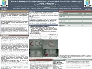
 Barium sulphate board for radiation protection
 Cardinal principles of radiation protection
 National radiation protection authority namibia
 Circuit training methods
 Ideal requirements of dental materials
 What are preventive dental material?
 Thermophysical properties of dental materials
 Auxiliary dental materials examples
 Who trains employees that work on scaffolds
 Fall protection training outline
 Child protection training materials
 Child protection awareness training
 Geometrical symbols
 Material usage variance = material mix variance +
 Time space compression ap human geography
 Refers to the knowledge language values customs
 Example of material culture
 Useful materials
 Dental core training
 Bullying and harassment training
 Disclaimer for training material
 Disclaimer for training material
 Disclaimer for training material
 Teamwork training module
 Training material development
 Ladder types ratings
 Open source six sigma training material
 Disclaimer for training material
 Counterfeit material awareness training
 Gmp training for employees
 Icpc training
 Middlesex radiology
 Isovue
 Radiology st1 competition ratio
 Hilgenreiner line
 Tcl radiology program
 Statdx
 Scottish radiology transformation programme
 Uva radiology tutorial
 Hlc accreditation
 Upside down grid error
 X ray protection
 Main chain scission radiology
 Radiology terminology
 Pnenumbra
 Oklahoma state radiology residency
 Straddle fracture radiology
 Radiology terminology
 Karisma radiology
 High pass filter radiology
 Vishwanath joshi
 El camino college radiology program
 Veterinary radiology dallas county
 Medial canthus radiology
 Difosfonate
 Ellis s shaped curve
 Veil glare radiology
 Ambient sistern
