
Radiation effects in spent nuclear fuel Dr Claire

- Slides: 26
Radiation effects in spent nuclear fuel Dr. Claire Corkhill University of Sheffield IAEA Workshop on radiation effects in nuclear waste forms and their consequences for storage and disposal, Trieste, September 2016
Outline • Introduction to spent fuel - Spent fuel microstructure and chemistry High burn up structure • Out-of-reactor radiation damage - Factors leading to swelling Defect accumulation Role of He • Effects of radiation on spent fuel disposal - Spent fuel dissolution Relationship between microstructure & dissolution Role of radiolysis on dissolution Dr. Claire Corkhill
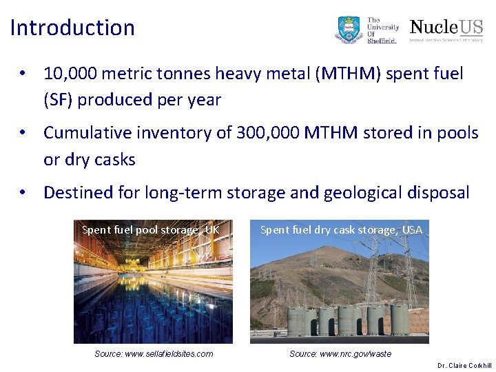
Introduction • 10, 000 metric tonnes heavy metal (MTHM) spent fuel (SF) produced per year • Cumulative inventory of 300, 000 MTHM stored in pools or dry casks • Destined for long-term storage and geological disposal Spent fuel pool storage, UK Source: www. sellafieldsites. com Spent fuel dry cask storage, USA Source: www. nrc. gov/waste Dr. Claire Corkhill
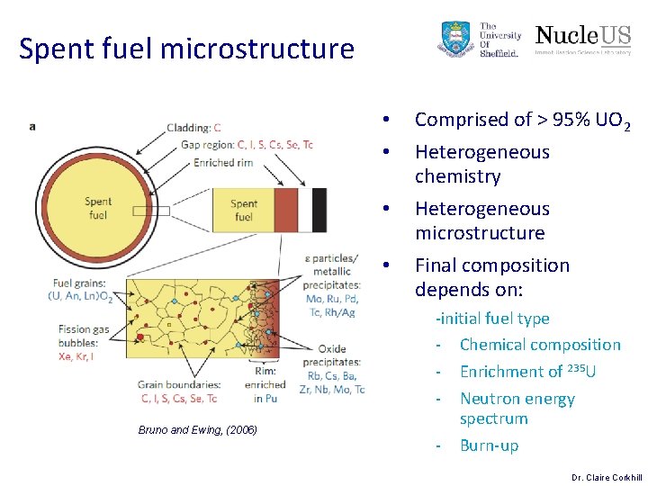
Spent fuel microstructure • • Bruno and Ewing, (2006) Comprised of > 95% UO 2 Heterogeneous chemistry Heterogeneous microstructure Final composition depends on: -initial fuel type - Chemical composition - Enrichment of 235 U - Neutron energy spectrum - Burn-up Dr. Claire Corkhill
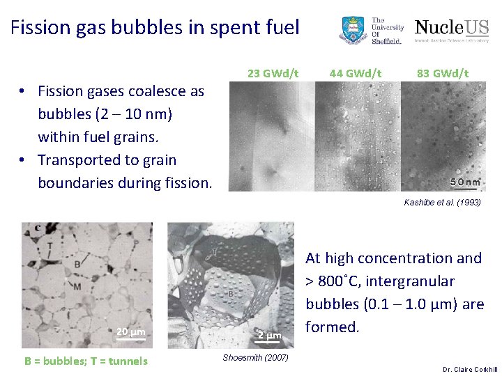
Fission gas bubbles in spent fuel • Fission gases coalesce as bubbles (2 – 10 nm) within fuel grains. • Transported to grain boundaries during fission. 23 GWd/t 44 GWd/t 83 GWd/t Kashibe et al. (1993) 20 µm B = bubbles; T = tunnels 2 µm At high concentration and > 800˚C, intergranular bubbles (0. 1 – 1. 0 µm) are formed. Shoesmith (2007) Dr. Claire Corkhill
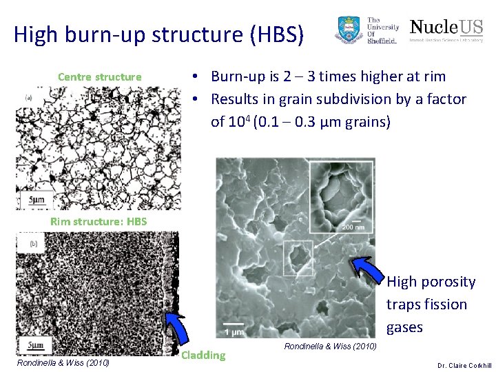
High burn-up structure (HBS) Centre structure • Burn-up is 2 – 3 times higher at rim • Results in grain subdivision by a factor of 104 (0. 1 – 0. 3 µm grains) Rim structure: HBS High porosity traps fission gases Rondinella & Wiss (2010) Cladding Rondinella & Wiss (2010) Dr. Claire Corkhill
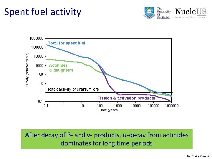
Spent fuel activity 1000000 Total for spent fuel Activity (relative scale) 100000 10000 Actinides & daughters 1000 10 1 Radioactivity of uranium ore Fission & activation products 0. 1 1 10 1000 Time (years) 1000000 After decay of β- and γ- products, α-decay from actinides dominates for long time periods Dr. Claire Corkhill
Problem: Volume swelling Self-irradiation α-damage He gas accumulation 20 µm 30 yr old Pu. O 2; Ferry et al. (2006) Dr. Claire Corkhill
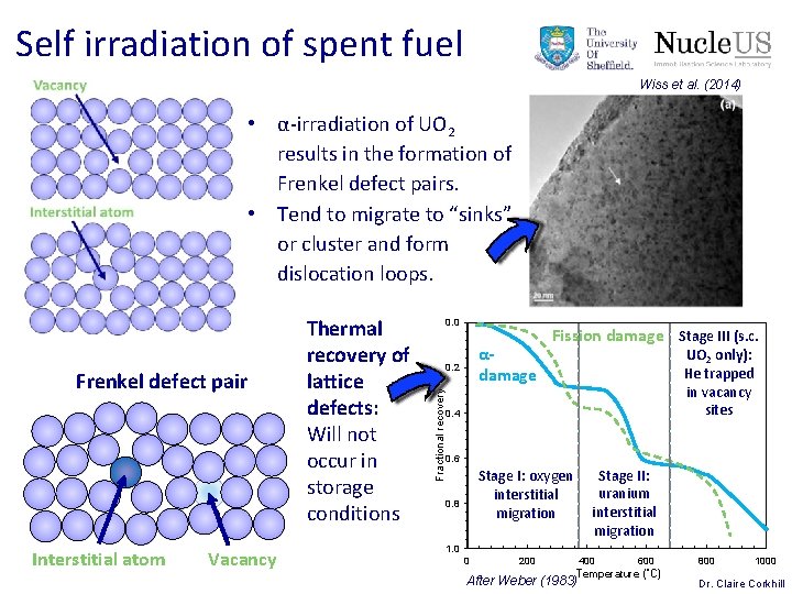
Self irradiation of spent fuel Wiss et al. (2014) • α-irradiation of UO 2 results in the formation of Frenkel defect pairs. • Tend to migrate to “sinks” or cluster and form dislocation loops. Interstitial atom Vacancy 0. 0 αdamage 0. 2 Fractional recovery Frenkel defect pair Thermal recovery of lattice defects: Will not occur in storage conditions Fission damage Stage III (s. c. UO 2 only): He trapped in vacancy sites 0. 4 0. 6 Stage II: uranium interstitial migration Stage I: oxygen interstitial migration 0. 8 1. 0 0 200 400 600 Temperature (˚C) After Weber (1983) 800 1000 Dr. Claire Corkhill
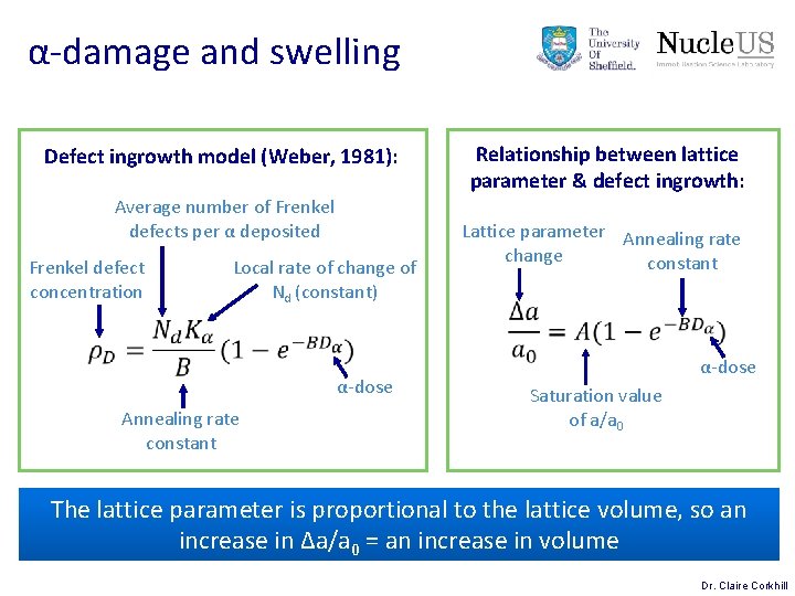
α-damage and swelling Defect ingrowth model (Weber, 1981): Average number of Frenkel defects per α deposited Frenkel defect concentration Local rate of change of Nd (constant) α-dose Annealing rate constant Relationship between lattice parameter & defect ingrowth: Lattice parameter Annealing rate change constant α-dose Saturation value of a/a 0 The lattice parameter is proportional to the lattice volume, so an increase in Δa/a 0 = an increase in volume Dr. Claire Corkhill
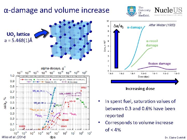
α-damage and volume increase Δa/a 0 After Weber (1983) UO 2 lattice a = 5. 468(1)Å Increasing dose • In spent fuel, saturation values of between 0. 3 and 0. 6% have been reported • Corresponds to volume increase of < 4% Wiss et al. (2014) Dr. Claire Corkhill
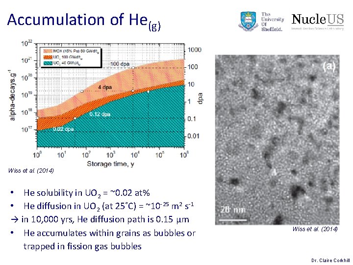
Accumulation of He(g) Wiss et al. (2014) • He solubility in UO 2 = ~0. 02 at% • He diffusion in UO 2 (at 25˚C) = ~10 -25 m 2 s-1 → in 10, 000 yrs, He diffusion path is 0. 15 μm • He accumulates within grains as bubbles or trapped in fission gas bubbles Wiss et al. (2014) Dr. Claire Corkhill
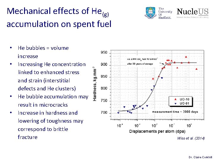
Mechanical effects of He(g) accumulation on spent fuel • He bubbles = volume increase • Increasing He concentration linked to enhanced stress and strain (interstitial defects and He clusters) • He bubble accumulation may result in microcracks • Increase in hardness and lowering of toughness may correspond to brittle fracture Wiss et al. (2014) Dr. Claire Corkhill
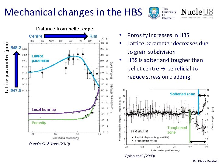
Mechanical changes in the HBS Distance from pellet edge Lattice parameter (pm) Centre 548. 2 Lattice parameter Rim • Porosity increases in HBS • Lattice parameter decreases due to grain subdivision • HBS is softer and tougher than pellet centre → beneficial to reduce stress on cladding 547. 5 Softened zone Local burn-up Porosity Toughened zone Rondinella & Wiss (2010) Spino et al. (2003) Dr. Claire Corkhill
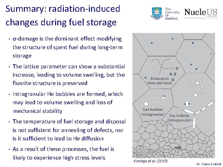
Summary: radiation-induced changes during fuel storage - α-damage is the dominant effect modifying the structure of spent fuel during long-term storage - The lattice parameter can show a substantial increase, leading to volume swelling, but the fluorite structure is preserved - Intragranular He bubbles are formed, which may lead to volume swelling and loss of mechanical stability - The temperature of fuel storage and disposal is not sufficient for annealing of defects, nor is it sufficient to lead to He diffusion - As a result of these processes, the fuel is likely to experience high stress levels Konings et al. (2015) Dr. Claire Corkhill
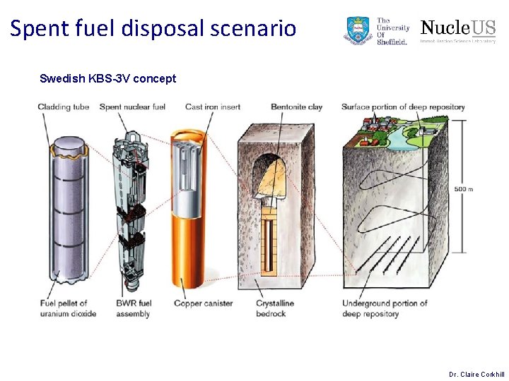
Spent fuel disposal scenario Swedish KBS-3 V concept Dr. Claire Corkhill
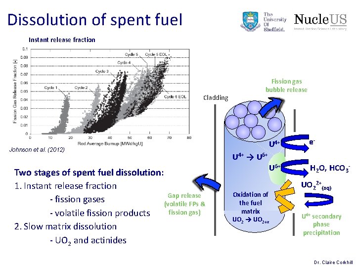
Dissolution of spent fuel Instant release fraction Cladding Johnson et al. (2012) Two stages of spent fuel dissolution: 1. Instant release fraction Gap release - fission gases (volatile FPs & fission gas) - volatile fission products 2. Slow matrix dissolution - UO 2 and actinides Fission gas bubble release U 4+ e- U 6+ H 2 O, HCO 3 - U 4+ → U 6+ Oxidation of the fuel matrix UO 2 → UO 2+x UO 22+(aq) U 6+ secondary phase precipitation Dr. Claire Corkhill
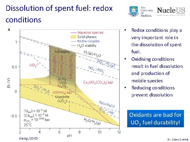
Dissolution of spent fuel: redox conditions • Redox conditions play a very important role in the dissolution of spent fuel. • Oxidising conditions result in fuel dissolution and production of mobile species • Reducing conditions prevent dissolution Oxidants are bad for UO 2 fuel durability! Ewing (2015) Dr. Claire Corkhill
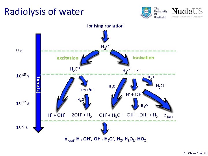
Radiolysis of water Ionising radiation H 2 O 0 s ionisation excitation H 2 O + e. H 2 O Time (s) 10 -15 s H 2 O* H 2+O(1 D) H 2 O 10 -12 s H 2 O+ H 2 O H- + OH˙ H 2 O H˙ + OH˙ 2 OH˙ + H 2 OH˙ + H 3 O+ OH˙ + OH- + H 2 e-(aq) 10 -6 s e-(aq), H˙, OH-, H 3 O+, H 2 O 2, HO 2 Dr. Claire Corkhill
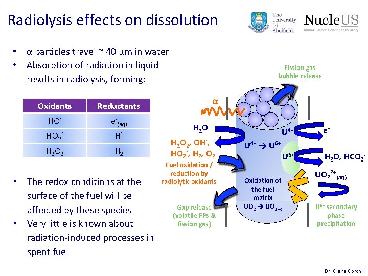
Radiolysis effects on dissolution • α particles travel ~ 40 μm in water • Absorption of radiation in liquid results in radiolysis, forming: Oxidants Reductants HO˙ e-(aq) HO 2˙ H˙ H 2 O 2 H 2 • The redox conditions at the surface of the fuel will be affected by these species • Very little is known about radiation-induced processes in spent fuel Fission gas bubble release α H 2 O 2, OH˙, HO 2˙, H 2, O 2 Fuel oxidation / reduction by radiolytic oxidants Gap release (volatile FPs & fission gas) U 4+ e- U 6+ H 2 O, HCO 3 - U 4+ → U 6+ Oxidation of the fuel matrix UO 2 → UO 2+x UO 22+(aq) U 6+ secondary phase precipitation Dr. Claire Corkhill
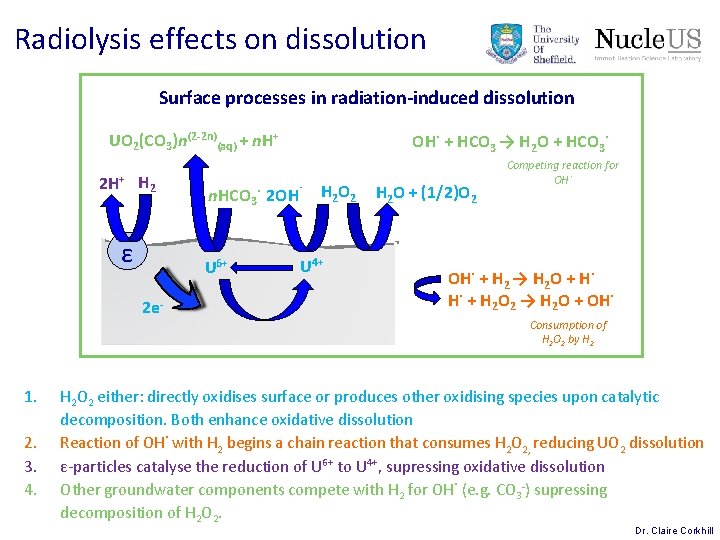
Radiolysis effects on dissolution Surface processes in radiation-induced dissolution UO 2(CO 3)n(2 -2 n)(aq) + n. H+ 2 H+ H 2 ε 1. 2. 3. 4. n. HCO 3˙ 2 OH˙ U 6+ 2 e- OH˙ + HCO 3 → H 2 O + HCO 3˙ H 2 O 2 U 4+ H 2 O + (1/2)O 2 Competing reaction for OH˙ + H 2 → H 2 O + H˙ H˙ + H 2 O 2 → H 2 O + OH˙ Consumption of H 2 O 2 by H 2 O 2 either: directly oxidises surface or produces other oxidising species upon catalytic decomposition. Both enhance oxidative dissolution Reaction of OH˙ with H 2 begins a chain reaction that consumes H 2 O 2, reducing UO 2 dissolution ε-particles catalyse the reduction of U 6+ to U 4+, supressing oxidative dissolution Other groundwater components compete with H 2 for OH˙ (e. g. CO 3 -) supressing decomposition of H 2 O 2. Dr. Claire Corkhill
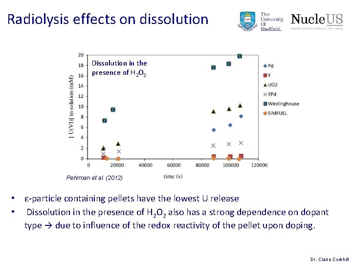
Radiolysis effects on dissolution Dissolution in the presence of H 2 O 2 Pehrman et al. (2012) • ε-particle containing pellets have the lowest U release • Dissolution in the presence of H 2 O 2 also has a strong dependence on dopant type → due to influence of the redox reactivity of the pellet upon doping. Dr. Claire Corkhill
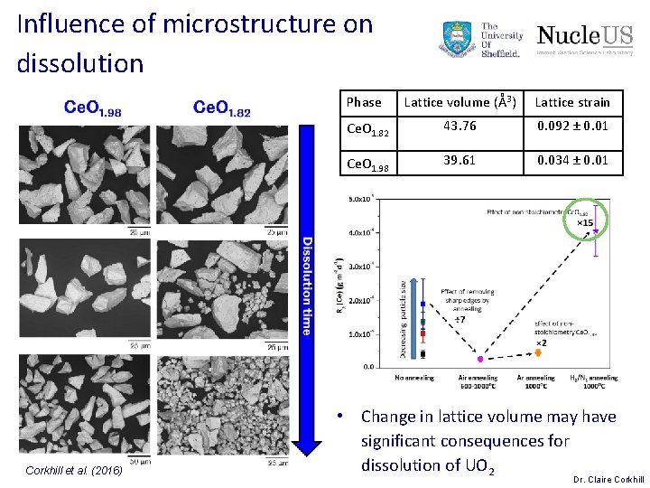
Influence of microstructure on dissolution Corkhill et al. (2016) Phase Lattice volume (Å3) Lattice strain Ce. O 1. 82 43. 76 0. 092 ± 0. 01 Ce. O 1. 98 39. 61 0. 034 ± 0. 01 • Change in lattice volume may have significant consequences for dissolution of UO 2 Dr. Claire Corkhill
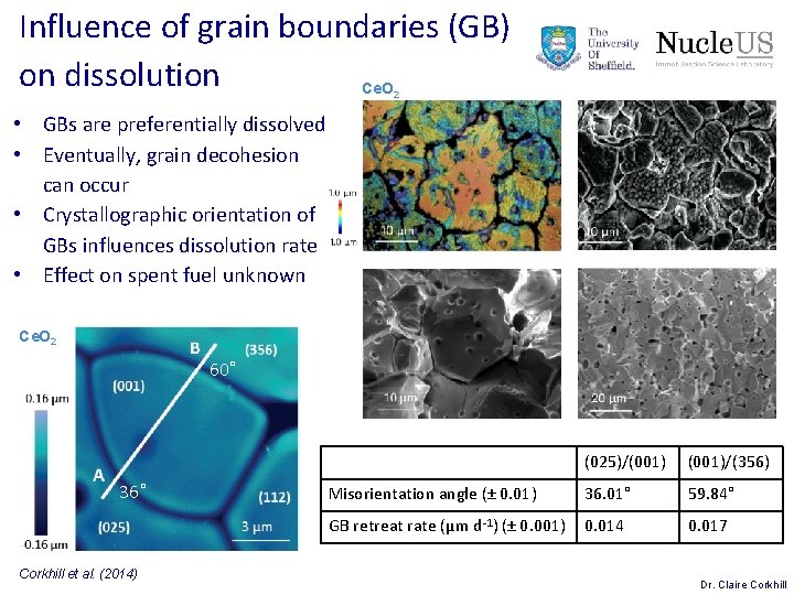
Influence of grain boundaries (GB) on dissolution Ce. O 2 • GBs are preferentially dissolved • Eventually, grain decohesion can occur • Crystallographic orientation of GBs influences dissolution rate • Effect on spent fuel unknown Ce. O 2 60˚ 36˚ Corkhill et al. (2014) (025)/(001)/(356) Misorientation angle (± 0. 01) 36. 01° 59. 84° GB retreat rate (μm d-1) (± 0. 001) 0. 014 0. 017 Dr. Claire Corkhill
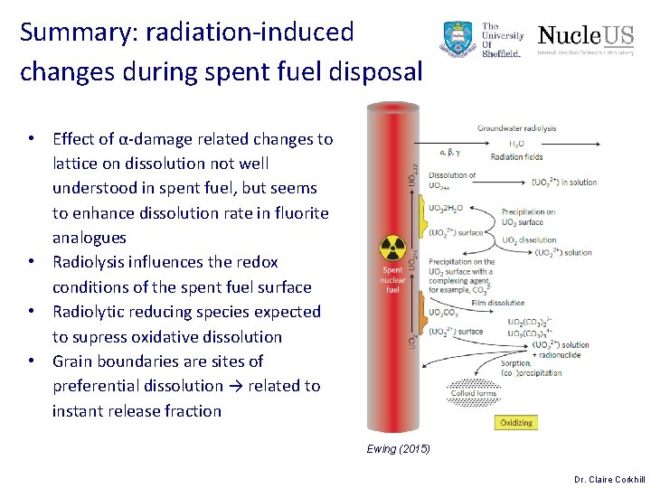
Summary: radiation-induced changes during spent fuel disposal • Effect of α-damage related changes to lattice on dissolution not well understood in spent fuel, but seems to enhance dissolution rate in fluorite analogues • Radiolysis influences the redox conditions of the spent fuel surface • Radiolytic reducing species expected to supress oxidative dissolution • Grain boundaries are sites of preferential dissolution → related to instant release fraction Ewing (2015) Dr. Claire Corkhill
References • • • • Bruno & Ewing, Elements, 2, 343 (2006) Corkhill et al. Applied Materials and Interfaces, 6, 12279 (2014) Corkhill et al. Applied Materials and Interfaces, 8, 10562 (2016) Ewing, Nature Materials, 14, 252 (2015) Johnson et al. Journal of Nuclear Materials, 420, 54 (2012) Kashibe et al. Journal Nuclear Materials, 206, 22 (1993) Konings et al. Nature Materials, 14, 247 (2015) Pehrman et al. Journal of Nuclear Materials, 430, 6 (2012) Rondinella & Wiss. Materials Today, 13, 24 (2010) Shoesmith, NWMO Report, TR-2007 -03 (2007) Spino et al. Journal of Nuclear Materials, 322, 204 (2003) Weber, Journal of Nuclear Materials, 98, 206 (1981) Weber, Journal of Nuclear Materials, 114, 213 (1983) Wiss et al. Journal of Nuclear Materials, 451, 198 (2014) Dr. Claire Corkhill