RADHABAI KALE MAHILA MAHAVIDYALAYA AHMEDNAGAR DEPARTMENT OF PHYSICS

RADHABAI KALE MAHILA MAHAVIDYALAYA, AHMEDNAGAR DEPARTMENT OF PHYSICS. POWER SUPPLY REPRESENTED BY Prof. Kapare A. K.

OBS. NO. ; NAME 1 IC 723 2 CAPACITOR 3 POTENTIOMETERE 4 DIODE 5 TRANSISTOR 6 RESISTOR 7 CED 8 TRANSFO RMER PICTURE

CAPACITOR Ø Capacitor store charges Ø It works as filter

RESISTOR Ø Ø Resistor is electrical component with primary function to limit the flow of current Resistor has four color code, The first two are: 1 st two digital and third multiplexer and 4 th tolerance

DIODE Diode is a device which allows flow of current in one direction. It is polarized component with two leads called cathode and anode The cathode normally marked the silver colored band

ZENER DIODE Zener : always in reverse bias It remove fluxuation

POTENTIOMETER Ø Ø Potentiometer have a three legs as a create voltage divider, basically two resistor in series Use: resistance adjust

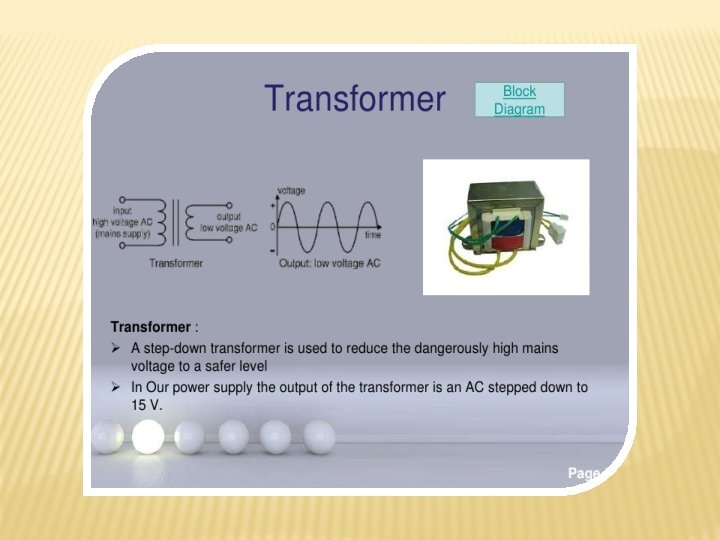
IC 723 This commonly use for series voltage regulator application It can be use as both positive and negative voltage regulator LM 723 IC can be use as temperatures controller, current regulator, available In both dual-in-line and metal can package.

Pin configuration Pin No. Pin Name Description 1 NC Not connected 2 Current Limit This terminal is used for current limiting 3 Current Sense This terminal is used for current limiting and foldback application 4 Inverting i/p Helps in providing constant output voltage 5 Non-inverting i/p Used to provide reference voltage to the op-amp inside 6 Vref Gives reference voltage of nearly 7 v 7 -Vcc Ground 8 NC Not connected 9 Vz Used in the application of negative voltage regulator 10 Vout Output pin of the IC 11 Vc This terminal is directly supplied from the supply when not connected to series pass transistor 12 V+ Positive supply input 13 Frequency Compensation This terminal helps in reducing noise, by adding a capacitor of 100 pf with it 14 NC Not connected

Internal Block diagram of LM 723 IC

Where to use LM 723 IC? LM 723 is an adjustable voltage regulator IC used for shunt regulator, current regulator, and temperature controller. It can able to provide a higher range of output voltage and current up to 10 A by simply adding a series pass transistor with it, with having a wider range of operating temperature so the IC able to withstand for long. Also able to use as either linear or switching type regulator. But this IC is specially designed for series regulator application.

CIRCUIT DIAGRAM

features ØExcessive output current of 150 m. A without external pass transistor. ØBetter Input supply voltage of maximum 40 v. ØProvide adjustable output from 3 v to 37 v. ØUsed in making linear or switching regulator. ØAble to provide 10 A of output current with use of external pass transistor. ØUsed for various operation like positive supply, negative supply, series, shunt, and floating.

THANK YOU
- Slides: 16