Radar Signals Tutorial I Radar Introduction and basic

Radar Signals Tutorial I: Radar Introduction and basic concepts

Outline Introduction to radar Radar history Radar principles Radar category Two important concepts Doppler effect Matched filter
 An aircraft was first located by radar in")
Radar history First radar test (1904) An aircraft was first located by radar in 1930 German high frequency engineer Christian Hulsmeyer Traffic supervision on water: he measures the running time of electro-magnetic waves to a metal ship and back Lawrence A. Hyland (Naval Research Lab) Radar development underwent a strong push during World War II

Radar principles A radar does nothing but measures the roundtrip time delay → the range R = c t / 2 radar: radio detection and ranging

The radar beam can be focused to a specific direction → azimuth and elevation Mechanical rotation / phased-array Radars work in high frequencies High resolution (small wavelength → small object) Small antenna size
 Over the horizon")
Frequency ranges GHz Airborne radar (small size, shirt range, high resolution) Over the horizon (high power, low resolution)
 transmitted power (w) antenna gain effective antenna aperture")
The radar equation received power (w) transmitted power (w) antenna gain effective antenna aperture (m 2) radar cross section (m 2)

Range ambiguity The radar time is set to zero each time a pulse is transmitted If echo signals from the first pulse arrive after the second pulse transmission, ambiguity arises Maximum unambiguous range

Range resolution Without intra-pulse modulation is the pulse width With intra-pulse modulation and range compression is the bandwidth of the pulse very small resolution 100 MHz → 1. 5 m

Angular resolution High directivity of radar antennas → small beam width → small resolution

Classification of radar systems
")
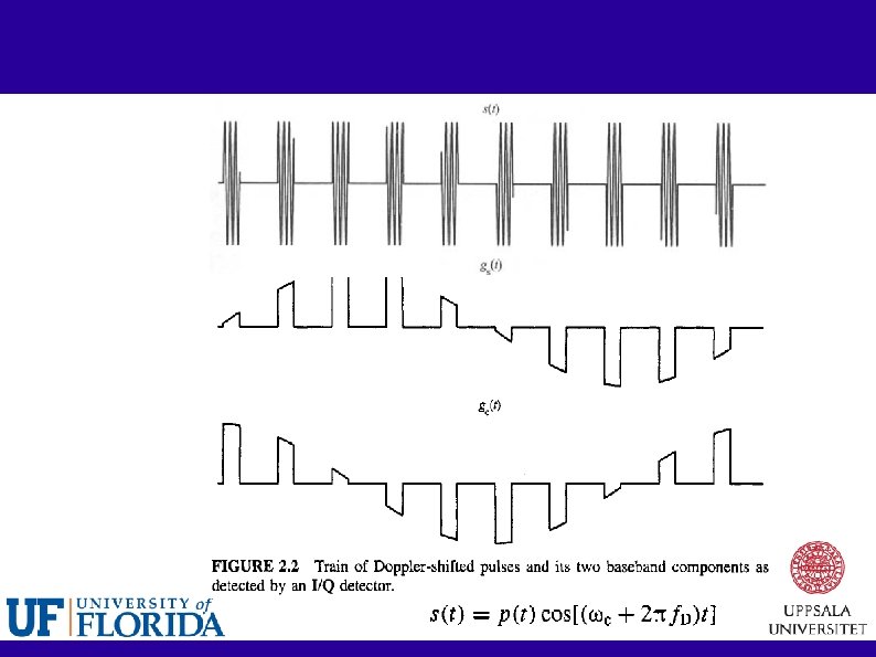
Doppler effect A ( )

Taylor expansion:

What if wideband signals? We cannot simply inverse T The received signal is a time-scaled and delayed version of the transmitted signal: envelop of the signal affected If bandwidth < 0. 1 carrier frequency, it is reasonable to assume that the motion causes only a Doppler shift to the carrier frequency.

Complex representation of signals Majority are narrow bandpass signals

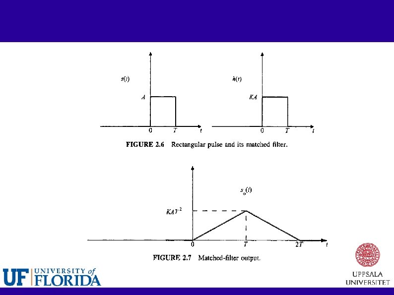
Matched filter Probability of detection is more related to SNR rather than the exact shape of the waveform A matched filter maximizes SNR at the output of the filter

Equality holds if and only if Matched filter output: Auto-correlation function

The matched filter Its impulse response is linearly related to the timeinverted complex-conjugate signal When the input to the matched filter is the correct signal plus white noise, the peak output is linearly related to the signal's energy. At the peak output, the SNR is the highest attainable, which is 2 E / N 0 The response is described by the autocorrelation function of the signal

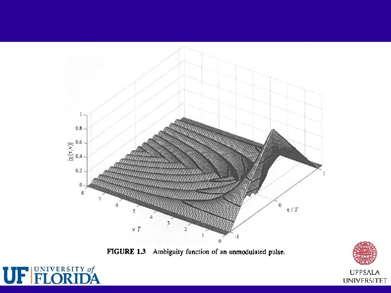
MF response to Doppler-shifted signals Ambiguity function The AF describes the output of a matched filter when the input signal is delayed by tau and Doppler shifted by nu relative to nominal values for which the matched filter was designed.

To be continued. . . Ambiguity function Various properties Basic radar signals Constant frequency pulse Linear-frequency modulated pulse A train of pulses Thank you Sep. 2009
- Slides: 23