RAD TECH A WEEK 2 RADIOGRAPHIC EQUIPMENT Spring

")


 TO PRODUCE X-RAYS YOU")


 is applied to the coil of wire electron")

 is applied to ANODE •")

 • Induction")


 B. MOLYBDENUM NECK OF ANODE C. STATORS")


 –")


 • What is set")
 • m. A- is")


- Slides: 91
RAD TECH A WEEK 2 RADIOGRAPHIC EQUIPMENT Spring 2009
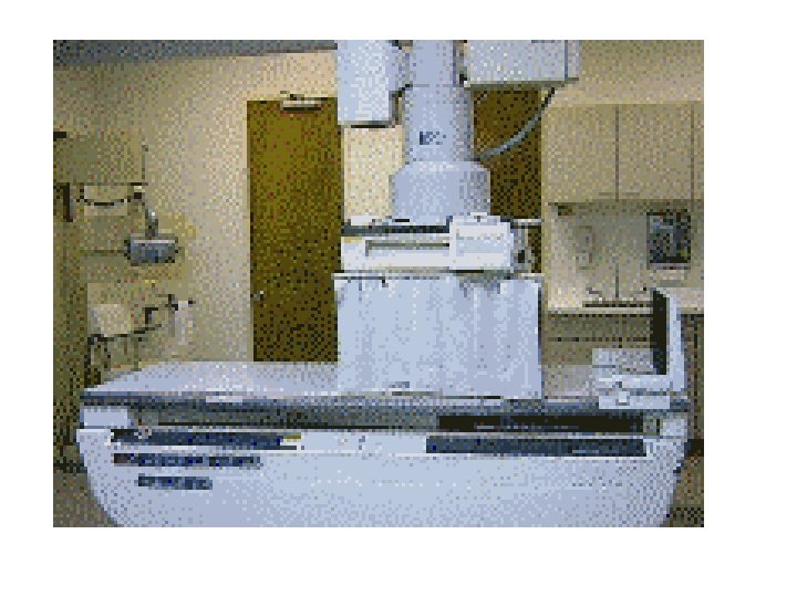
RADIOGRAPHIC EQUIPMENT RTA Week 2 Ch. 8 & 9 - pg (110 & 111)
Radiographic Room
OBJECTIVES • IDENTIFY GENERIC COMPONENTS OF THE RADIOGRAPHIC EQUIPTMENT • DESCRIBE VARIOUS PLANES OF X-RAY TUBE AND TABLE MOVEMENT
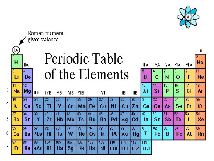
A look inside the body • X-rays are a form of electromagnetic energy. X-rays have high enough energy to penetrate the human body leaving different densities on the image below • Dependant on the Z# of the material
The Electromagnetic Spectrum • X-rays have wavelengths much shorter than visible light, but longer than high energy gamma rays MEASURED IN ANGSTROM 0. 1 – 0. 5 FOR X-RAYS
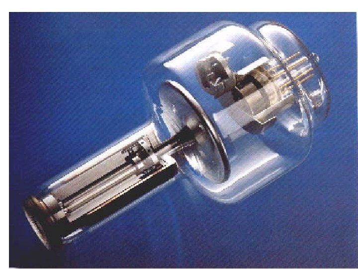
THE X-RAY TUBE • The X-Ray tube is the single most important component of the radiographic system. It is the part that produces the X-rays
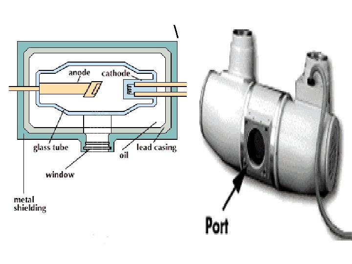
THE X-RAY TUBE • GLASS ENCASED IN STURDY STEEL HOUSING • PRIMARY COMPONENTS ANODE + & CATHODE --
How “X-rays” are created SEE: MAN MADE RADIATION (PG. 93) TO PRODUCE X-RAYS YOU NEED: • A SOUCE OF ELECTONS • A FORCE TO MOVE THEM QUICKLY • SOMETHING TO STOP THEM SUDDENLY
PRODUCTION OF X RAYS Requirements: – a source of fast moving electrons – must be a sudden stop of the electrons’ motion – in stopping the electron motion, kinetic energy (KE) is converted to EMS energies • Infrared (heat), light & x-ray energies
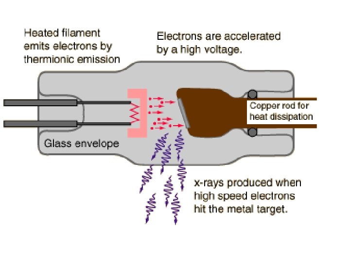
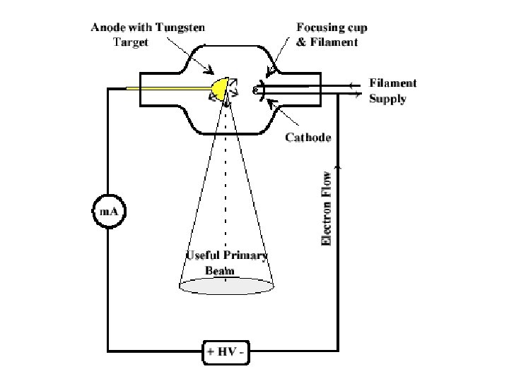
How Are X-rays Made? • X-rays are produced when electrons strike a metal target. • The electrons are released from the heated filament and accelerated by a high voltage towards the metal target. • The X-rays are produced when the electrons collide with the atoms (electrons) of the metal target.
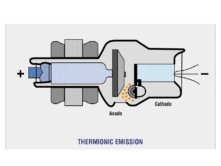
How “X-rays” are created • Power is sent to x-ray tube via cables • m. A (milliamperage) is sent to filament on cathode side. • Filament heats up – electrons “boil off” • Negative charge
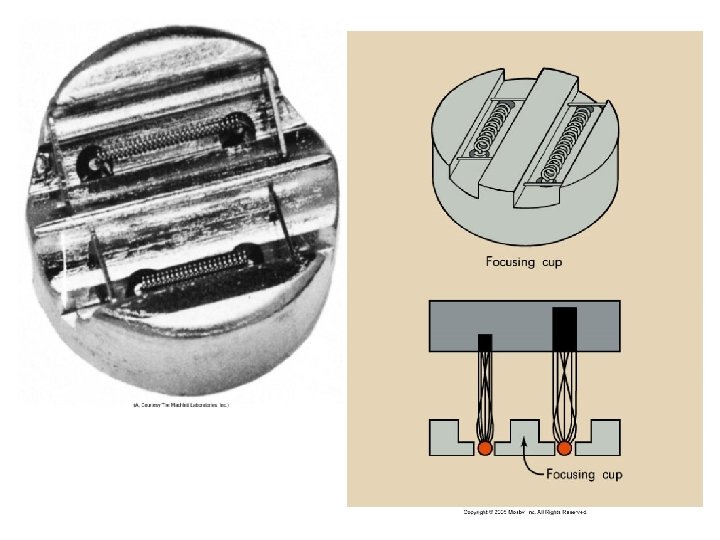
Cathode • Filament – Dual-filament • Focusing cup
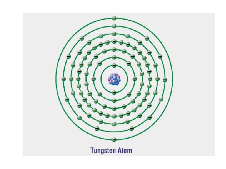
Tungsten • Filaments are usually made of tungsten • Tungsten provides higher thermionic emission than other metals • Tungsten has a very high melting point
Filament • When current (m. A) is applied to the coil of wire electron are ejected • The outer-shell electrons of the filament atom are “boiled off”. – This is known as thermionic emission
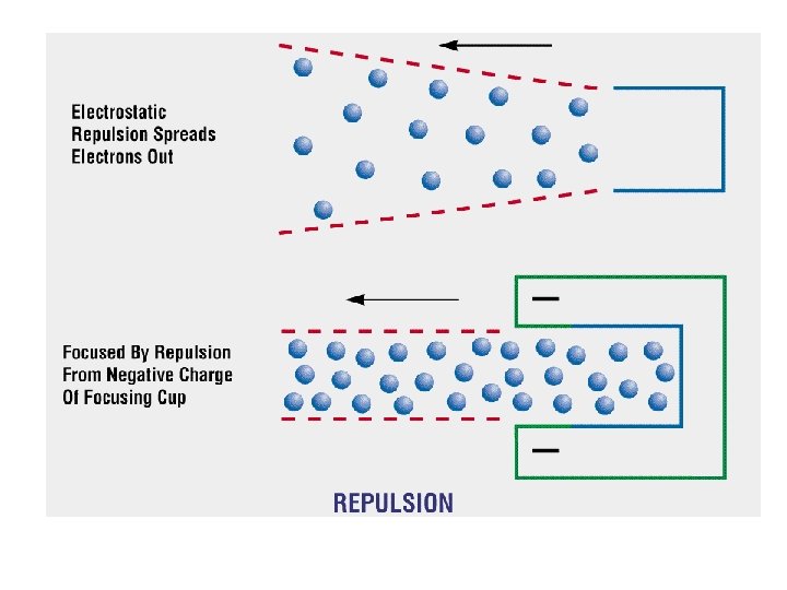
Focusing cup • The filament is embedded in a metal cup that has a negative charge • Boiled off e- tend to spread out due to electrostatic repulsion. The focusing cup confines the e- cloud to a small area
How “X-rays” are created • Positive voltage (k. Vp) is applied to ANODE • Negative electrons = attracted across the tube to the positive ANODE. • Electrons “slam into” anode – suddenly stopped. • X-RAY PHOTONS ARE CREATED
Mechanical support for the target
Anodes - Target Rotating Anodes • 2” to 5” disk (focal track) • Induction motor Cu • W Speed 3000 to 10000 rpm Molybdenum or Graphite base • Common target material is Tungsten • Electrons interact with W – photons created
X-ray Production e- e- etarget e- e- e- e- eeee- e- e- e-e- e- anode electrons • electrons move at high speed (k. V) • collide with target on anode • k. V of electrons converted to x rays & heat
How “X-rays” are created • Electron beam is focused from the cathode to the anode target by the focusing cup • Electrons interact with the electrons on the tungsten atoms of target material • PHOTONS sent through the window PORT – towards the patient
TUBE HOUSING MADE OF LEAD & STEEL
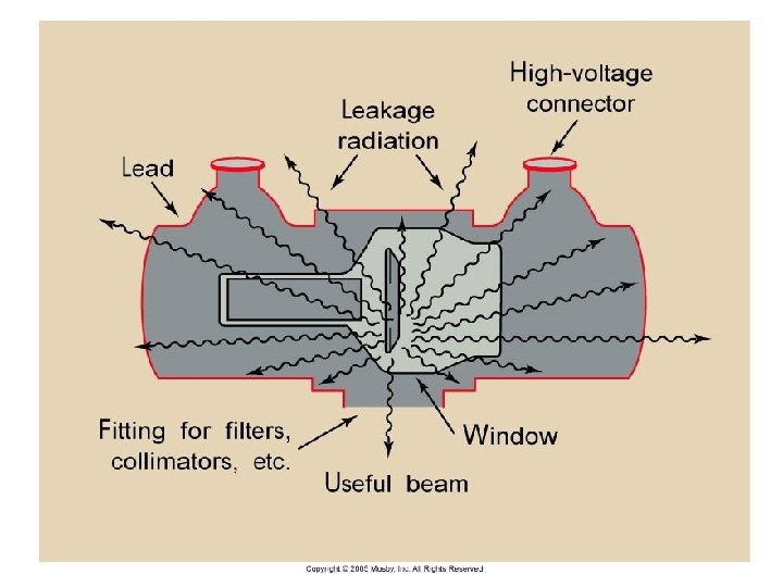
XRAY TUBE HOUSING • MADE OF LEAD AND STEEL • TO ABOSRB ANY STRAY RADIATION • TO PREVENT X-RAY PHOTONS TO LEAK FROM THE TUBE
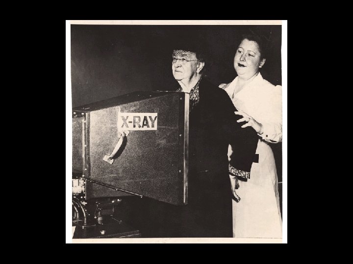
Early X-ray Tube
X-RAY TUBE • MADE OF PYREX GLASS TO WITHSTAND HIGH HEAT LOAD • IS GAS EVACUATED – (so electrons won’t collide with the air molecules in the tube)
X-ray Tube Construction A C B D E Radiographic Equipment G F
X-ray Tube Construction A. GLASS HOUSING (ENVELOPE) B. MOLYBDENUM NECK OF ANODE C. STATORS /ELECTROMAGNETS D. TUNGSTEN ANODE (FOCAL SPOT) E. WINDOW OR PORT FOR BEAM EXIT F. FILAMENT (CATHODE) G. FOCUSING CUP
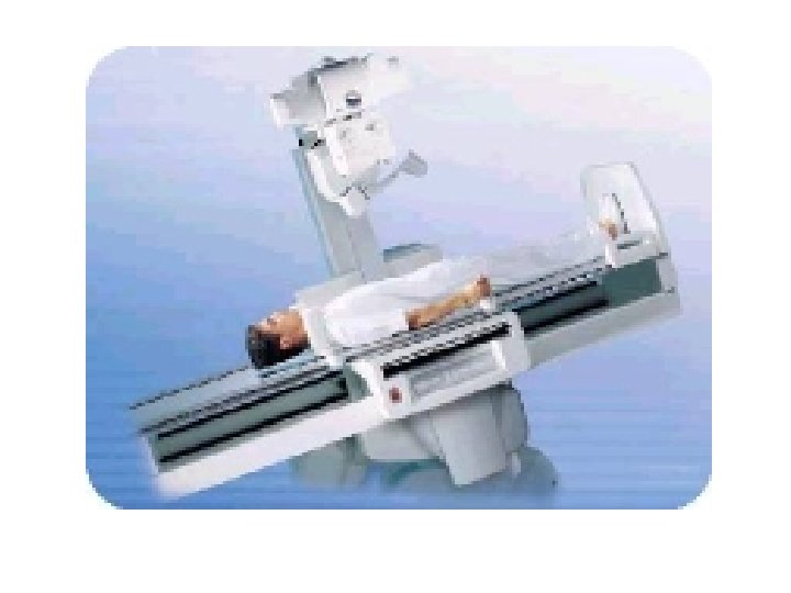
X-RAY TABLE
Radiographic tables n Are designed to support the patient during a radiographic exam n Comfort is not the primary concern n Foam pads should be used if the patient will be required to be on the table for longer than 10 minutes
Tabletop Must be uniformly radiolucent to easily permit x-ray to pass through. n Carbon fiber is used because it is strong and very little x-ray photons are absorbed. n Usually tabletops are flat however some are curved n
Tabletop Most tabletops are floating, some are motor-driven n The brakes can be released usually by the technologist hand or foot n The brakes are electromagnetic n Floating table tops save significant amounts of time and strain on the technologist n
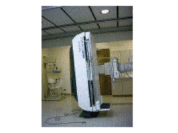
Tables • Tilting rooms are designed for both diagnostic and fluoroscopic work – Tilting models usually tilt to 90 degrees in one direction and 15 – 30 degrees in the other direction – Tilting models include ancillary equipment; footboard, shoulder support, handgrips, compression bands
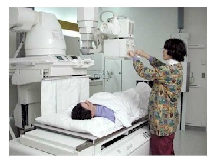
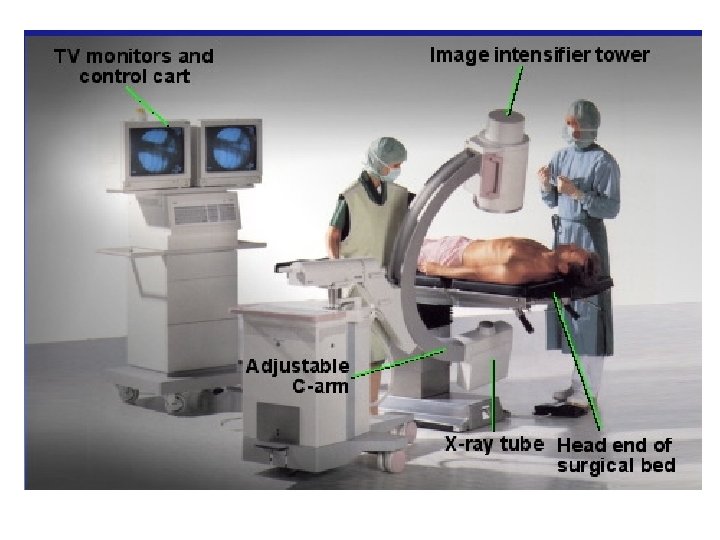
FLUOROSCOPY IMAGES IN MOTION
REMOTE ROOM & OLD CONVENTIONAL FLUORO
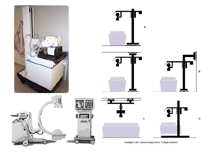
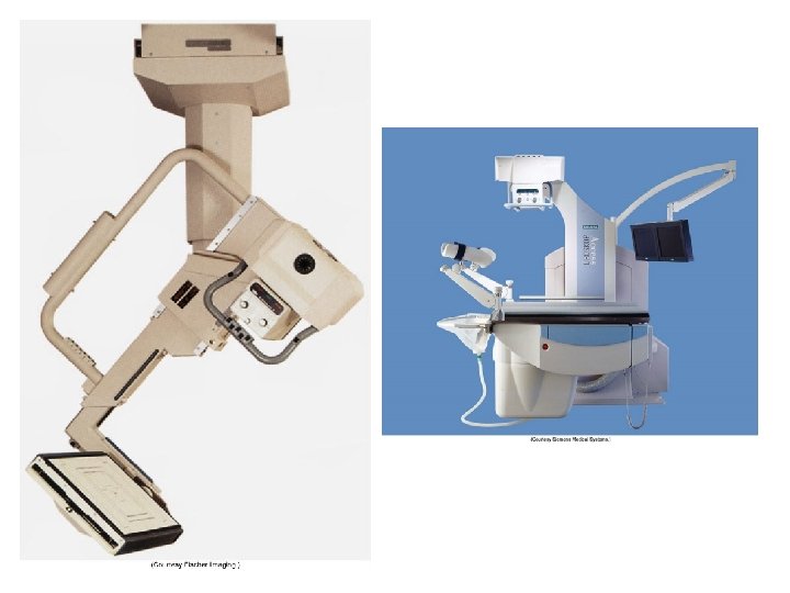
Tube Supports • Designed to help technologists with various tube locations for creative imaging. • Tube suspension systems are available in 5 versions: – ceiling mounted, floor-to-ceiling, floor, mobile and c-arm.
Tube Movement • • • Longitudinal Transverse Vertical Angling or Rolling Rotating Telescoping
TABLE OR UPRIGHT BUCKY TRAY
The ‘BUCKY’ • The bucky is the device in the table or chest board that holds the film cassette. The ‘bucky’ is like a drawer that opens and closes to insert and remove the film cassette.
Radiographic grid & bucky tray
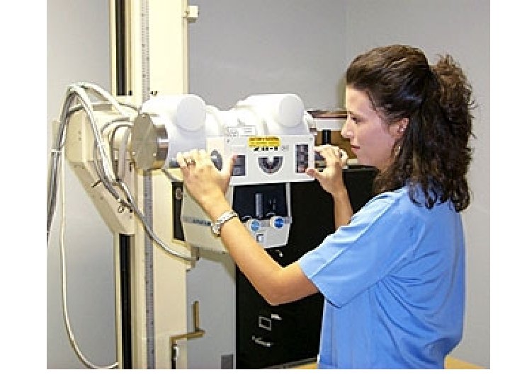
COLLIMATOR • ATTACHES DIRECTLY BELOW THE X-RAY TUBE • SERVES AS A X-RAY BEAM LIMITING DEVISE • CONTROLS THE SIZE AND SHAPE OF X-RAY FIELD
Cone collimator
• ALWAYS KEEP THE COLLIMATED AREA SMALLER THAN THE SIZE OF THE CASSETTE
RADIOGRAPH • PERMANENT RECORD MADE USING RADIATION – RADIO- RADIATION (usually x rays) – GRAPH PERMANENT RECORD (film)
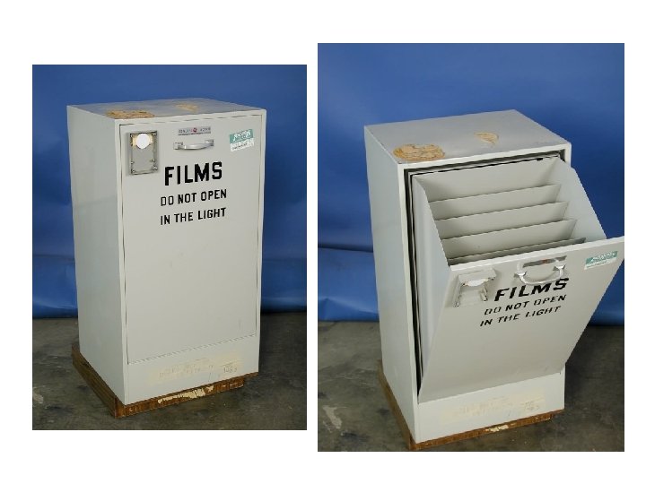
UNEXPOSED FILM PLACED IN A CASSETTE
CASSETTE or FILM HOLDER • The CASSETTE is used to hold the film during examinations. It consist of front and back intensifying screens, and has a lead (Pb) backing. The cassette is light tight
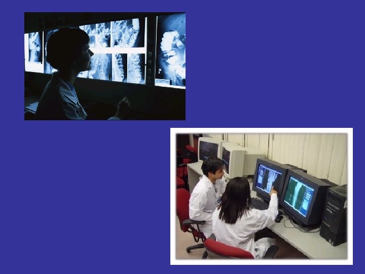
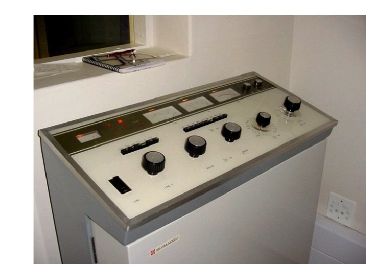
CONTROL CONSOLE • GIVES THE TECHNOLOGIST CONTROL OF THE X -RAY MACHINE • TECHNIQUE SELECTION • Located OUTSIDE of the Radiographic Room
The Control Console • The control console is device that allows the technologist to set technical factors (m. As & k. Vp) and to make an exposure. • Only a legally licensed individual is authorized to energize the console.
“Technique” k. Vp , m. As (m. A x s) • What is set at the control panel • How the “image” is created on the “film” or Image receptor (digital) • k. Vp controls the “ENERGY” of the beam • The Higher k. Vp – more penetrating • Ranges is 50 -110 in Diagnostic x-ray
“Technique” k. Vp , m. As (m. A x s) • m. A- is the current in combination with the time – determines HOW LONG the beam will stay on • Controls the density on the film/image
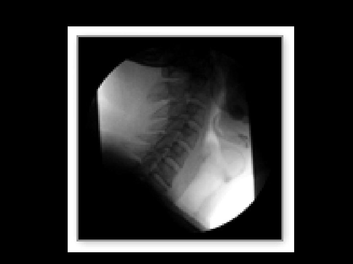
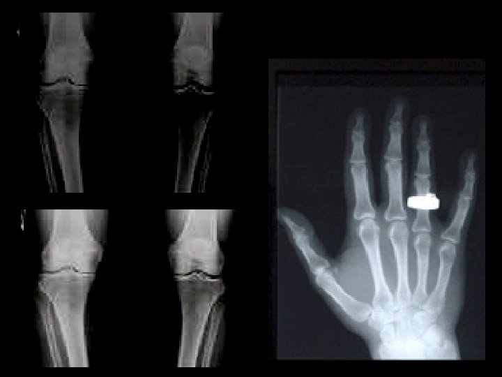
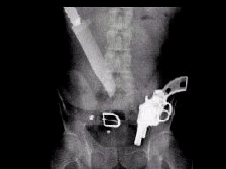
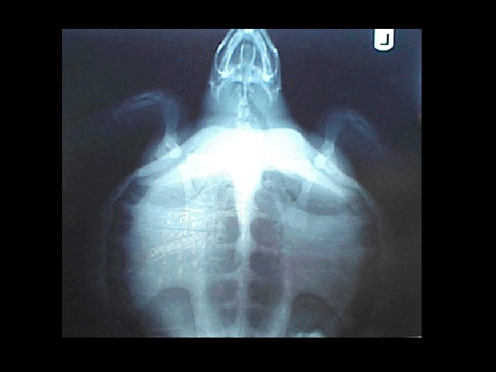
Why you see what you see • The films or images have different levels of denisty – different shades of gray • X-rays show different features of the body in various shades of gray. • The gray is darkest in those areas that do not absorb X-rays well – and allow it to pass through • the images are lighter in dense areas (like bones) that absorb more of the X-rays.
IMAGES • DENSITY = THE AMOUNT OF BLACKENING “DARKNESS” ON THE RADIOGRAPH - m. As controlled • CONTRAST – THE DIFFERENCES BETWEEN THE BLACKS TO THE WHITES - k. Vp controlled
+ 30% + 50 % mas
k. Vp Changes
What is in the Darkroom?
Analog processor
Darkroom
Safe Light • 15 Watts • Red filter • Must be 3 -6 feet from counter top or feed tray of processor • Used to be amber or orange filter
Computerized Radiography CR processor • What a digital processor looks like • No darkroom required
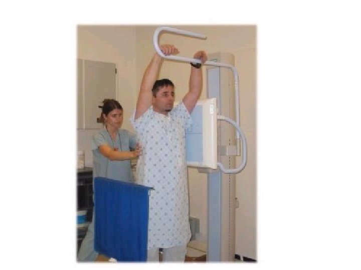
CHEST X-RAY IS THE MOST COMMONLY Analog or Digital PERFORMED PROCEDURE
Other x-ray stuff…. • Positioning phantoms • Pixie
Other x-ray stuff…. • Positioning sponges • Lead markers • Gurney
RTA LAB 1 : EQUIPMENT • Next week…. . • TOUR OF THE IONIZING LAB HERE ON CAMPUS. • COMPLETE IN CLASS WORKSHEET FOR TERMINOLOGY