
Quote of the day Week 2 Voltage Current










- Slides: 59
Quote of the day
Week 2: Voltage & Current Measurement EKT 112: PRINCIPLES OF MEASUREMENT AND INSTRUMENTATION
Introduction of electric circuit The ultimate goal of the circuit theory is to predict currents and voltages in complex circuits (circuit analysis) and to design electrical circuits with desired properties. The circuits are built with circuit elements. Some of these elements (voltmeters, ammeters, wires, resistors, capacitors, inductors, and switches) are described below.
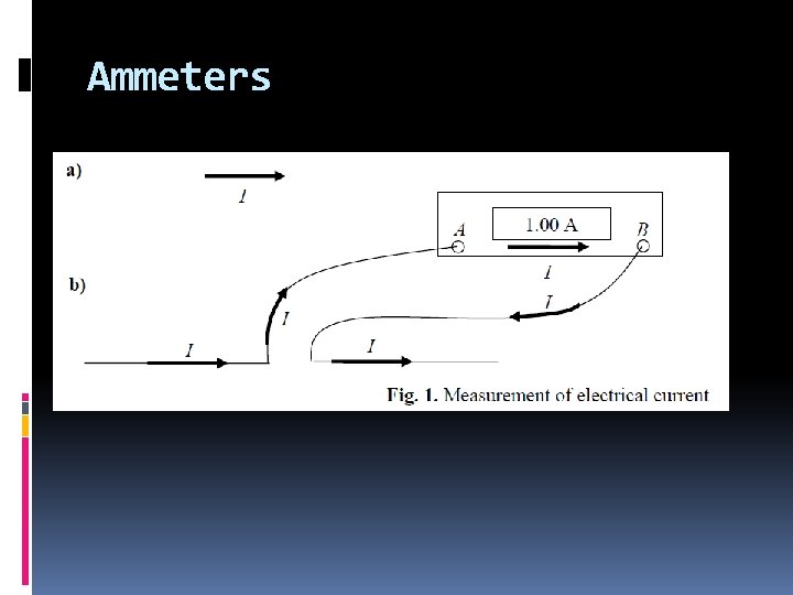
Voltmeters and Ammeters Electrical currents can be measured with an ammeter. To measure the current in the wire shown in Fig. 1 a, the wire should be cut and the ammeter should be inserted. The current will flow through the ammeter (Fig. 1 b).
Ammeters
Ammeters An ideal ammeter should have a negligible effect on the circuit. This means that the voltage difference between its two terminals (A and B) should be zero. In other words, the internal resistance (impedance) of an ideal ammeter is zero.
Voltmeter
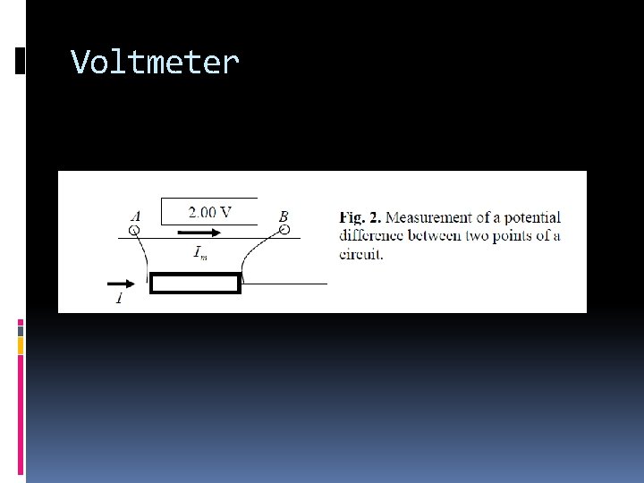
Voltmeter To measure voltage, the two terminals of a voltmeter should be connected to two points in the circuit between which the potential difference is measured. An ideal voltmeter should not affect the circuit. Therefore, current through the voltmeter (this is current in Fig. 2) should be zero. In other words, internal resistance (impedance) of an ideal voltmeter is infinity. A real voltmeter is never ideal and its impedance is finite.
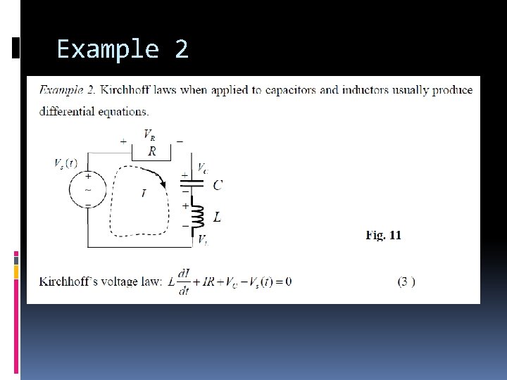
Kirchhoff laws are applicable to both the linear and not linear circuits. They provide a universal tool for circuit analysis.
Kirchhoff laws Kirchhoff’s current law: The sum of the currents entering a node is equal to the sum of currents leaving the node. A node is a point where two or more wires are interconnected.
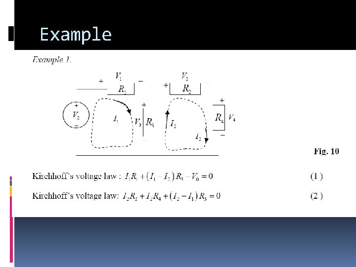
Kirchhoff laws Kirchhoff’s voltage law: An algebraic sum of voltages across all elements along any closed path is zero. Algebraic sum means that we should take + sign if the voltage rises after a circuit element and “–“ sign if the voltage drops after a circuit element.
Kirchhoff laws (cont…) Analysis of a circuit. General rules: 1. Identify every loop which does not contain another loop (such a loop is called mesh). Assign a current for every loop. The current direction can be chosen arbitrary. This step ensures that the Kirchhoff’s current law is automatically satisfied. 2. Use Ohm’s law (or other relations between voltages and currents if the circuit includes capacitors, inductors, diodes, etc) to calculate the voltage across all elements along every mesh and write equations (for every mesh) using. Kirchhoff’s voltage law. Important! If two currents flow through an element, the currents should be added like vectors (their directions are important!). 3. Solve the equations.
Example
Example 2
PART 2
CURRENT, VOLTAGE & RESISTANCE MEASUREMENT
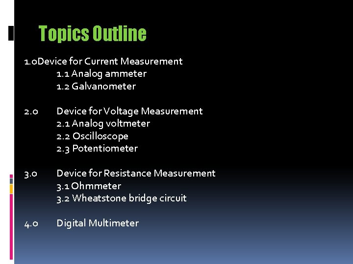
Topics Outline 1. 0 Device for Current Measurement 1. 1 Analog ammeter 1. 2 Galvanometer 2. 0 Device for Voltage Measurement 2. 1 Analog voltmeter 2. 2 Oscilloscope 2. 3 Potentiometer 3. 0 Device for Resistance Measurement 3. 1 Ohmmeter 3. 2 Wheatstone bridge circuit 4. 0 Digital Multimeter
Objective As introduction to the student into some basic measurement device for current, voltage & resistance.
Electrical Indicating Instruments and Measurement Electrical instruments are classified into two 1. Absolute instruments The value of the electrical quantity to be measured are given by these intruments. The quantity are measured in terms of constants and from deflection of the instruments only. Example : Tangent galvanometer.
2. Secondary instruments The value of the electrical quantity to be measured is determined from the defletion of these instruments. With an absolute instrument these instruments are calibrated. There are three categories of secondary instruments 1. Indicating instruments 2. Recording instruments 3. Integrating instruments
Indicating instruments Recording intsruments The value of the electrical quantity is indicated by these instruments at the time when it is being measured. Pointers moving over the scale give the indication. Example s: Ammeters, volmeters and wattmeter A continuous record of variations of the electrical quantity over a long period of time is given by these instruments. It has a moving system which carries an inked pen which rest tighhtly on a graph chart. Example s: Graphic recorders and Galvanometer recorders.
Integrating instruments The total amount of either electricity or electrical energy supplied over a period of time is measured by these instruments. Example : Ampere hour meters, watt hour meter, energy meters
1. 0 CURRENT MEASUREMENT
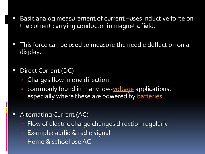
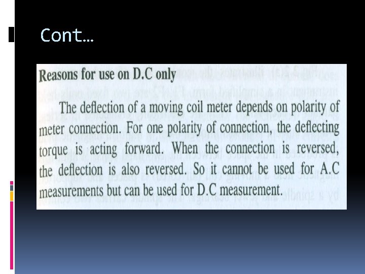
Basic analog measurement of current –uses inductive force on the current carrying conductor in magnetic field. This force can be used to measure the needle deflection on a display. Direct Current (DC) Charges flow in one direction commonly found in many low-voltage applications, especially where these are powered by batteries Alternating Current (AC) Flow of electric charge changes direction regularly Example: audio & radio signal Home & school use AC
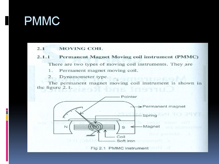
PMMC
Cont…
Cont…
Cont…
Cont…
Cont…
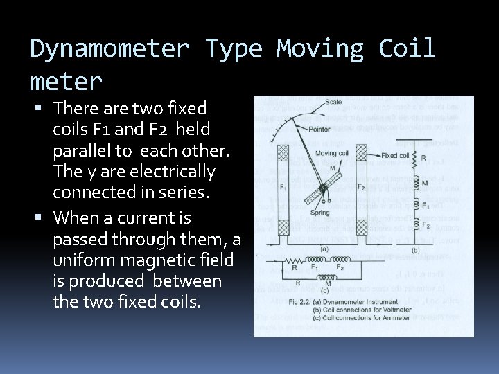
Dynamometer Type Moving Coil meter There are two fixed coils F 1 and F 2 held parallel to each other. The y are electrically connected in series. When a current is passed through them, a uniform magnetic field is produced between the two fixed coils.
Cont… Within this magnetic field a moving coil is placed and support by a spindle and jewel bearings. The spindle carries two control springs that also serve as current leads to the moving coil. Moving coil can be connected either in series or parallel with fixed coil. Series connection – voltmeter Parallel connection – ammeter
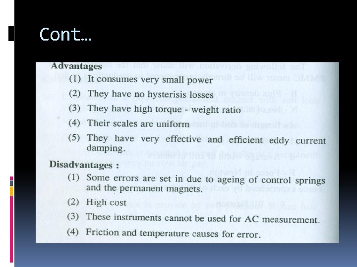
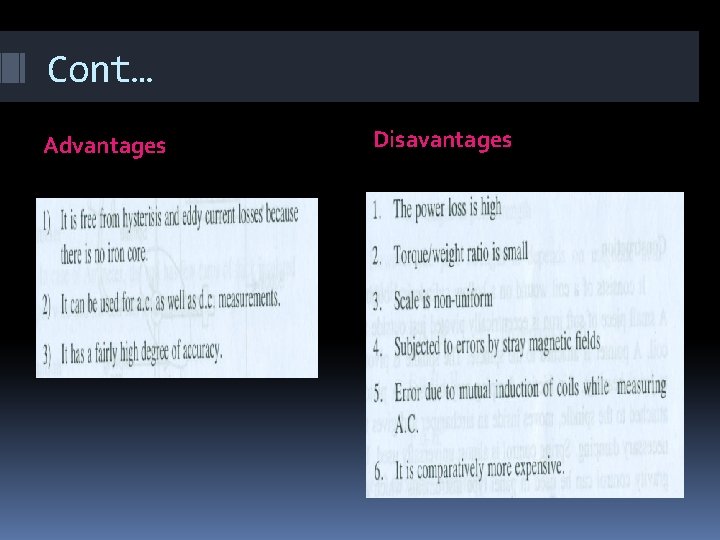
Cont… Advantages Disavantages
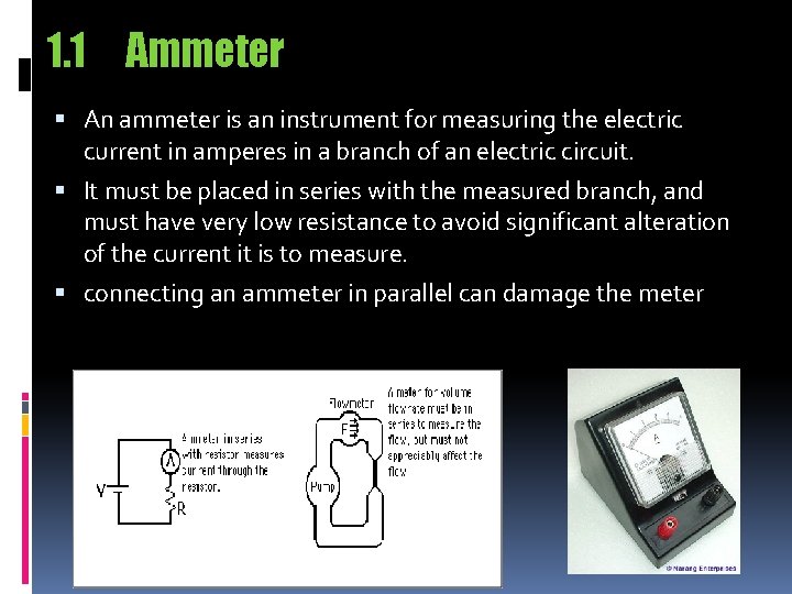
1. 1 Ammeter An ammeter is an instrument for measuring the electric current in amperes in a branch of an electric circuit. It must be placed in series with the measured branch, and must have very low resistance to avoid significant alteration of the current it is to measure. connecting an ammeter in parallel can damage the meter
Ammeter – Principle of Operation The earliest design is the D'Arsonval galvanometer or moving coil ammeter (respond to ac only) It uses magnetic deflection, where current passing through a coil causes the coil to move in a magnetic field The voltage drop across the coil is kept to a minimum to minimize resistance across the ammeter in any circuit into which the it is inserted. Moving iron ammeters use a piece or pieces of iron which move when acted upon by the electromagnetic force of a fixed coil of (usually heavy gauge) wire (which respond to both dc & ac)
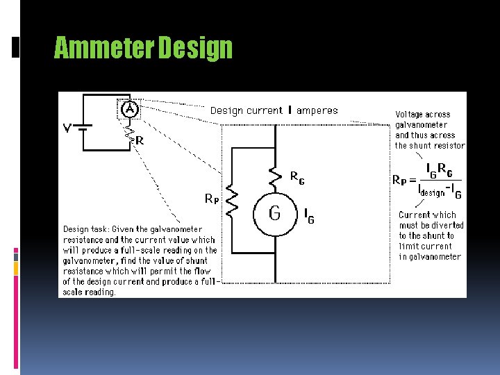
Ammeter Design
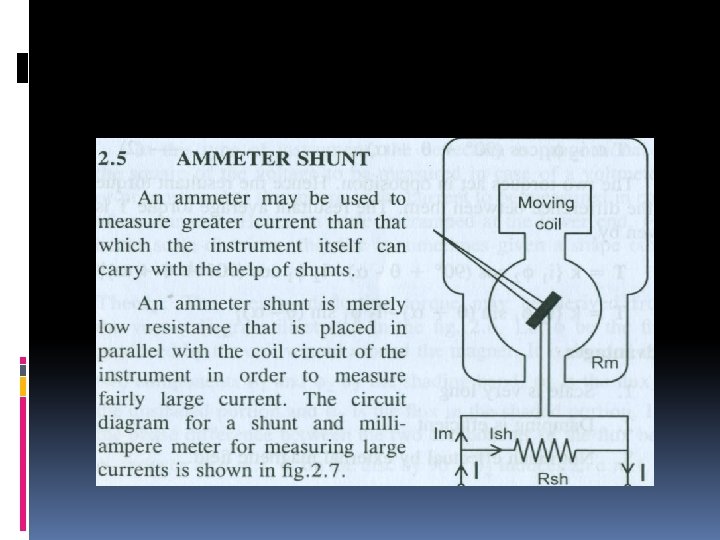
An ammeter is placed in series with a circuit element to measure the electric current flow through it. The meter must be designed offer very little resistance to the current so that it does not appreciably change the circuit it is measuring. To accomplish this, a small resistor is placed in parallel with the galvanometer to shunt most of the current around the galvanometer. Its value is chosen so that when the design current flows through the meter it will deflect to its full-scale reading. A galvanometer full-scale current is very small: on the order of milliamperes.
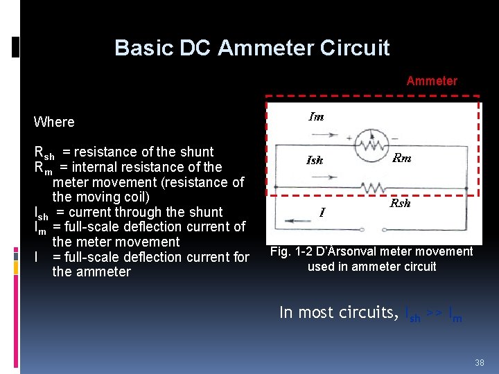
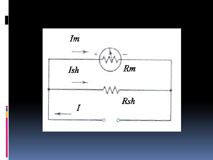
Basic DC Ammeter Circuit Ammeter Where Rsh = resistance of the shunt Rm = internal resistance of the meter movement (resistance of the moving coil) Ish = current through the shunt Im = full-scale deflection current of the meter movement I = full-scale deflection current for the ammeter Fig. 1 -2 D’Ársonval meter movement used in ammeter circuit In most circuits, Ish >> Im 38
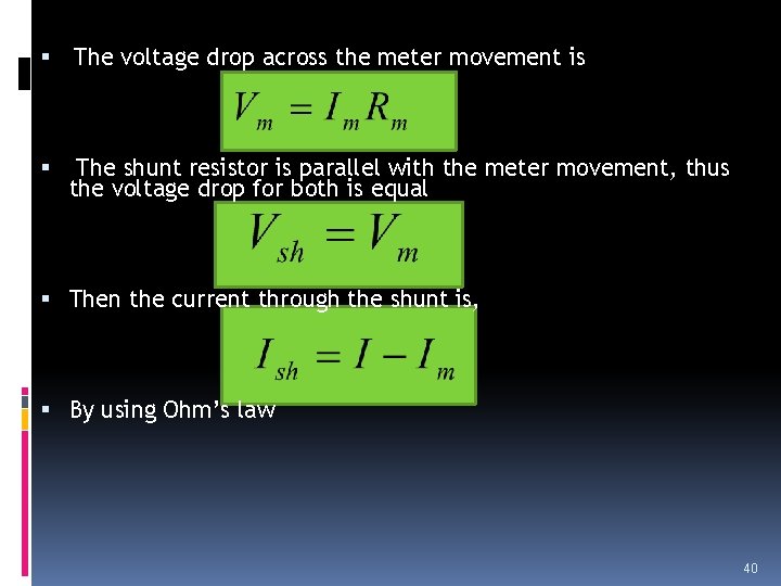
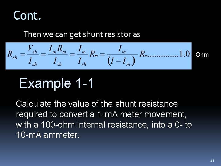
The voltage drop across the meter movement is The shunt resistor is parallel with the meter movement, thus the voltage drop for both is equal Then the current through the shunt is, By using Ohm’s law 40
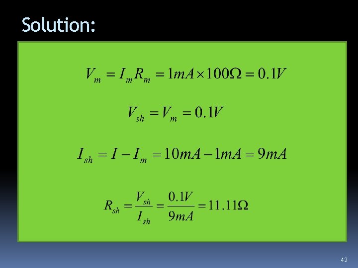
Cont. Then we can get shunt resistor as Ohm Example 1 -1 Calculate the value of the shunt resistance required to convert a 1 -m. A meter movement, with a 100 -ohm internal resistance, into a 0 - to 10 -m. A ammeter. 41
Solution: 42
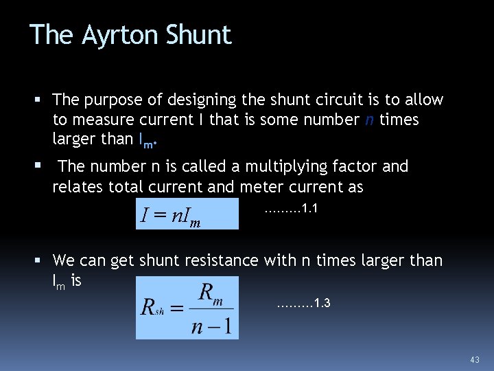
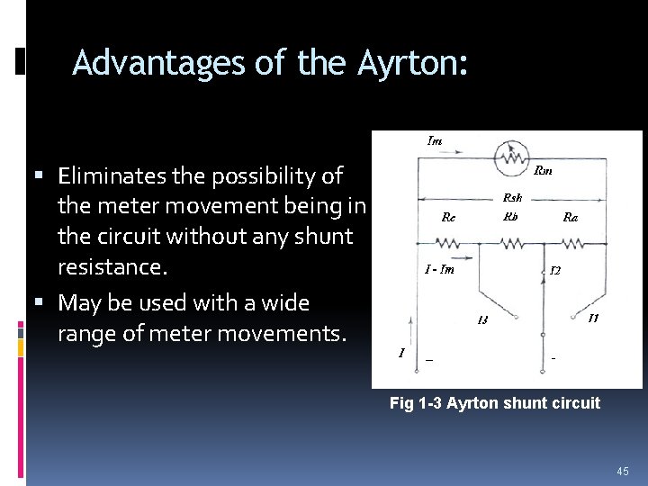
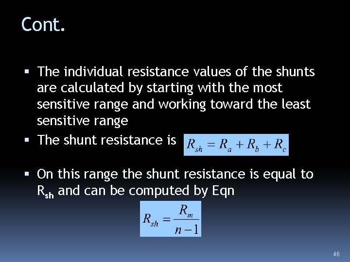
The Ayrton Shunt The purpose of designing the shunt circuit is to allow to measure current I that is some number n times larger than Im. The number n is called a multiplying factor and relates total current and meter current as I = n. Im ……… 1. 1 We can get shunt resistance with n times larger than Im is ……… 1. 3 43
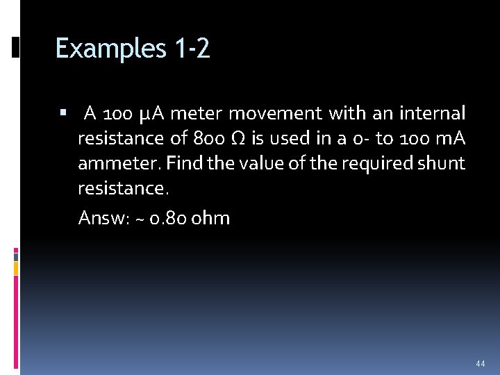
Examples 1 -2 A 100 µA meter movement with an internal resistance of 800 Ω is used in a 0 - to 100 m. A ammeter. Find the value of the required shunt resistance. Answ: ~ 0. 80 ohm 44
Advantages of the Ayrton: Eliminates the possibility of the meter movement being in the circuit without any shunt resistance. May be used with a wide range of meter movements. Fig 1 -3 Ayrton shunt circuit 45
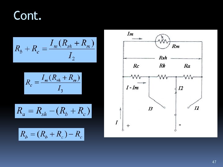
Cont. The individual resistance values of the shunts are calculated by starting with the most sensitive range and working toward the least sensitive range The shunt resistance is On this range the shunt resistance is equal to Rsh and can be computed by Eqn 46
Cont. 47
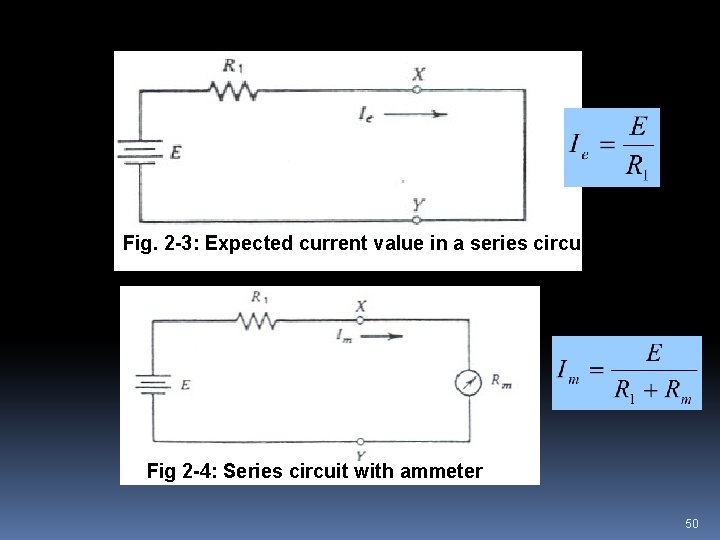
Ammeter insertion effects Inserting an ammeter in a circuit always increases the resistance of the circuit and reduces the current in the circuit. This error caused by the meter depends on the relationship between the value of resistance in the original circuit and the value of resistance in the ammeter. 48
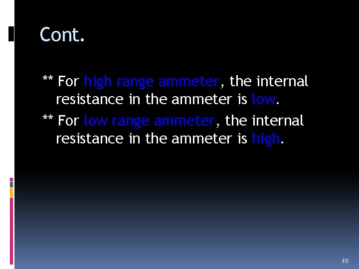
Cont. ** For high range ammeter, the internal resistance in the ammeter is low. ** For low range ammeter, the internal resistance in the ammeter is high. 49
Fig. 2 -3: Expected current value in a series circuit Fig 2 -4: Series circuit with ammeter 50
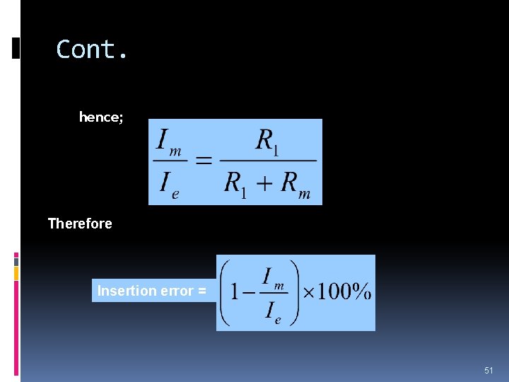
Cont. hence; Therefore Insertion error = 51
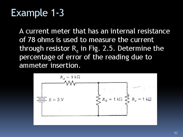
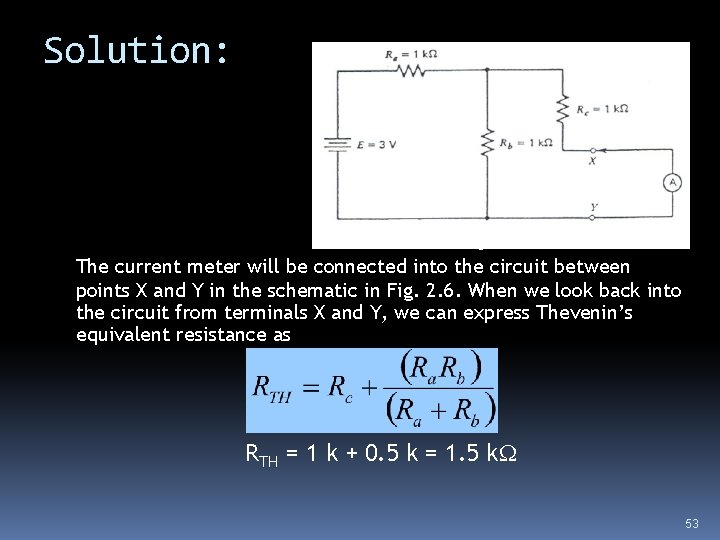
Example 1 -3 A current meter that has an internal resistance of 78 ohms is used to measure the current through resistor Rc in Fig. 2. 5. Determine the percentage of error of the reading due to ammeter insertion. Fig. 2. 5 52
Solution: Fig. 2 -6 The current meter will be connected into the circuit between points X and Y in the schematic in Fig. 2. 6. When we look back into the circuit from terminals X and Y, we can express Thevenin’s equivalent resistance as RTH = 1 k + 0. 5 k = 1. 5 k 53
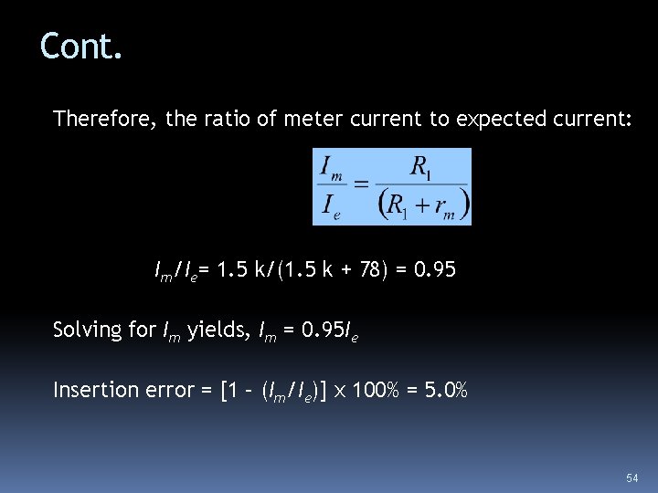
Cont. Therefore, the ratio of meter current to expected current: Im/Ie= 1. 5 k/(1. 5 k + 78) = 0. 95 Solving for Im yields, Im = 0. 95 Ie Insertion error = [1 – (Im/Ie)] x 100% = 5. 0% 54
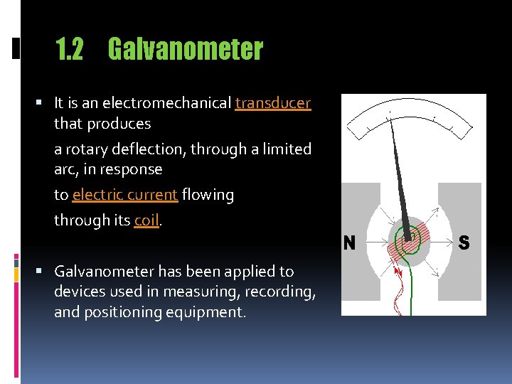
1. 2 Galvanometer It is an electromechanical transducer that produces a rotary deflection, through a limited arc, in response to electric current flowing through its coil. Galvanometer has been applied to devices used in measuring, recording, and positioning equipment.
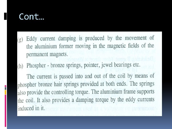
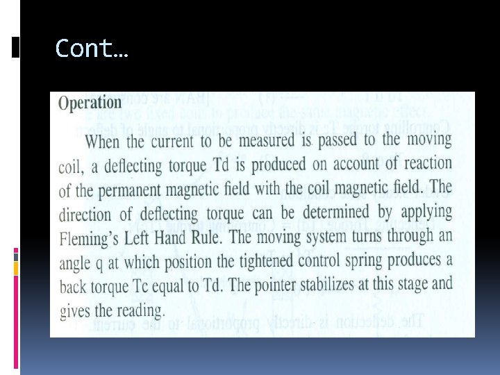
Galvanometer – Principle of Operation Such devices are constructed with a small pivoting coil of wire in the field of a permanent magnet. The coil is attached to a thin pointer that traverses a calibrated scale. A tiny spring pulls the coil and pointer to the zero position. In some meters, the magnetic field acts on a small piece of iron to perform the same effect as a spring. When a direct current (DC) flows through the coil, the coil generates a magnetic field. This field acts with or against the permanent magnet. The coil pivots, pushing against the spring, and moving the pointer. The hand points at a scale indicating the electric current. A useful meter generally contains some provision for damping the mechanical resonance of the moving coil and pointer so that the pointer position smoothly tracks the current without excess vibration.
Galvanometer – Application Are used to position the pens of analog chart (example: electrocardiogram)
Thank You