q MINE DEVELOPMENT BY RAMLAKHAN MEENA DEPARTMENT OF

q MINE DEVELOPMENT BY : RAMLAKHAN MEENA DEPARTMENT OF MINING SS COLLEGE OF ENGINEERING , UDAIPUR

q. SHAFT SINKING Ø General aspects of shaft sinking Mine shafts are not just holes or pits in ground. Although, they may be called ‘pits’, shafts are properly equipped, since they have several important jobs to do. Also, shafts are built, that is sunk, with precision; and their shapes, sizes and sites have to be carefully chosen beforehand. Job shafts link the surface or ‘pit-top’ and the underground or ‘pit-bottom’ part of a mine.

What shafts do ? Shafts, being links between pit-top and pitbottom, have several important jobs to do: Ø WINDING Providing ways for coal to be raised. Providing ways for men to be lowered and raised. Other winding (Supplies, machines, ponies etc. )

Ø PUMPING Holding pipes for water which is pumped out of the mine for disposal. Holding pipes for water which is taken down the mine for fire fighting, dust suppression, drinking water for ponies. Ø POWER Holding pipes for compressed air which is forced down the mine. Holding cables for electricity which is taken down the mine.

Ø SIGNALLING Holding telephone and other signalling wires. Ø VENTILATION Taking fresh air into the mine. Bringing used air out of the mine.

Why pair of shafts ? A mine has to have at least a pair of shafts. The law says there must be two ways of entering and leaving a mine. If, for example, the winding breaks down in one shaft, then the men can be raised through the other. Ventilation is the other reason. Fresh air has to be taken into the mine and used air brought out of the mine. So, one shaft is needed for fresh air to go down. This is called the ‘downcast’ shaft and is marked D. C. on mine plans. The colour for fresh or intake air on plans is BLUE.

From D. C pit-bottom the air splits into separate streams, each stream going round one district – giving oxygen to men, ponies and flame safety lamps; cooling them and the machines; collecting moisture, dust and dangerous gases.

When the air has done its work and has become used air, another shaft is needed for it to come up. This is called the ‘up cast’ shaft and is marked U. C. on the mine plans. The colour used air on plans is Red for return.

ØWinding A pair of shafts is necessary also for the winding that has to be done. While coal is being raised in one shaft, some men and supplies can be lowered and raised in the other shaft at the same time. In this way the coal is moved to the surface without interruption. Since the tubs cannot run up or down a shaft, they are put in lifts called ‘cages’. As the cage carrying full tubs comes up, another empty tub goes down.

Cages can have one or more decks, taking one or more tubs per deck. With multi-deck cages special arrangements can be made to enable the tubs to enter the cage decks simultaneously. Usually the cages pass one another halfway in the shaft. Each cage is suspended on a steel winding rope which passes over a pulley in the headgear, each cage must be supported from underneath by catches or ‘keps’.

There are many kinds of headgears, but whatever the design, headgears have to withstand a very great load – sometimes over 100 tonnes. In a headgear the feet of the back stays are set well back for strength. A headgear provides height above ground level not only for unloading tubes but also for avoiding what is known as overwind. Should the cage be wound up too far, a detaching hook detaches the rope from the cage; the rope flies over the pulley and the cage is supported in the headgear on the ‘detaching the hook plate’.

Special equipment is fitted to the winding engine to control the overwinds and to slow down the cage considerably before landing when the men are being wound. Winding engines are driven by steam or electricity.

Cross section of head gear

ØPit Bottom Winding and haulage meet at pit-bottom. The haulage brings the full tubs or mine cars from the loading stations or pit- bottom. Here the coal is transferred from haulage to winding. In this way winding finishes the job of moving the coal from face to the surface. The way the transfer of coal from haulage to winding takes place depends on whether tubs or mine cars are left at pit bottom or taken to pit top.
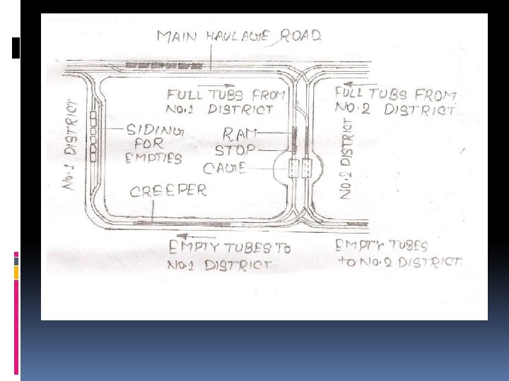

If full tubs are to be wound up the shaft, they arrive at the pit bottom from loading stations along the main haulage road. They are stopped in front of the shaft and then pushed by hand or special rams into cages to be taken to the surface. As the full tubs are rammed into cages, they push the empty tubs out of the cages; the empties have come down from pit top. They run down a slope on the other side of the shaft – some to the left and some to right. Then they are raised to a higher level by creepers. The creepers are endless chains with projections which push against the axles of the tubs. Then the empties run down to the main haulage road to be returned to the loading stations.

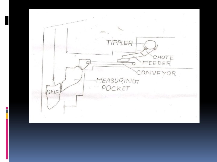
If the tubs or cars are to remain underground, the coal is emptied by means of a tippler which turns over a car at a time. The coal is fed on to a conveyor which takes it to the shaft side. There the coal slides into measuring pockets which measure out skipfuls of coal. The skips are containers like cages with the difference that they are enclosed and wind coal without tubs up the shaft.

ØUp the shaft Once the coal is in the skips or the cages, it is raised up the shaft. To do this job safely and efficiently the shaft has to have all sorts of equipment which is carefully chosen and used, regularly inspected and maintained and changed when necessary. Each cage must have a separate way to travel. Otherwise it will collide with the cage travelling in the opposite direction. The cages either run non rails of steel fixed to girders across the shaft- on ‘rigid guides’ – or are guided by steel ropes called ‘guide ropes’. Usually guide ropes are made of thick steel wires. These are sometimes surrounded by a layer of shaped wires which interlock – ‘locked coil ropes’ – giving smooth, lasting ropes. The guide ropes are supported by clamps resting on cross girders in the headgear. They are kept taut by weights –‘cheese weights’- suspended below the loading level at the pit bottom. On each cage are bolted shoes which surround the guide ropes and allow the cage to slide up and down the shaft.

v Between the cage and the winding rope there is following equipment: Ø Cage chains: There are six chains: either each chain taking its share of load, or the four corner chains carrying load – with the two middle chains remaining slack ready to take a share of the load should a corner chain break. Ø Distributing plate: The chains are held over a cage by distributing plate which brings their upper ends together.

Ø Detaching hook: This is so made that when it strikes the sides of the detaching hook plate in the headgear its jaws open at the top, releasing the rope with its capel; at the same time sprouts projections on its sides and hold the cage on the plate. Ø Rope capel: This is a clamp, the lower end of which is connected to the detaching hook; its upper end grips the rope. There are several types of capels, but in all of them the grip on the rope is so arranged that it tightens as the load pulls.

The winding rope itself must be strong. It must also be flexible, since it bends over the headgear pulley and the winding engine drum; and it must be non-rotating so as not to twist the cage. The latter is achieved, in making the rope, by laying the outer layer of strands in the opposite direction to the inner layer of strands. The rope becomes flexible and strong by having many strands and many steel wires in each strand. Although not as flexible, but because they can be made much stronger, special types of locked coil ropes are used for winding in very deep shafts.

Cross section of shaft

ØPit Top When the cages or skips reach the pit top, the coal has to be unloaded. The method of unloading depends on whether the coal is wound in cages or skips.

If full tubs are raised to pit top in cages, they are pushed out of the cages by empty tubs as the empties are pushed into the cages by hand or rams on the other side of the shaft. The empties are lowered down the shaft, whilst the full tubs run down by a retarder placed before the station. Then the full tubs are raised up a slope to a higher level by a creeper. From there the full tubs run down to the tipplers into which they are pushed by hand or another set of rams. The coal drops down on to conveyors which take nit to the screens. The tubs, which are now empty, continue on their way to the shaft. They are rammed into the cages which take them down again.

If the coal is wound up the shaft in skips, it is emptied by them into a receiving pocket at pit top. From there it is fed on to conveyors which take it to the screens. As soon as a skip is emptied, it goes down the shaft again.

q. Other Jobs Ø SIGNALLING Shafts hold telephone and other signalling wires which link pit-top with pit-bottom. Winding, for example, could not be carried on safely and efficiently, without proper and constant signalling by authorized persons. Telephone wires pass through shafts from the surface and extend right into the districts. The regular working of a mine depends on reliable lines of communication.

Ø POWER Shafts hold pipes for compressed air which is forced down the mine or cables for electricity which is taken down the mine, or both. Power is needed in the pit to operate haulage engines and conveyors, as well as coal cutters, drills and compressed air picks. Electricity is also used for general lighting in places like pit-bottoms, road junctions, engine rooms and pumping rooms. Ø PUMPING Shafts hold pipes for water which, being dirty and sometimes in large quantities, is continuously pumped out of the mine for disposal. The water collects at pitbottom in storage spaces called ‘sumps’. It is brought there in pipes from underground districts. From there it is pumped up the pipes in the shafts.

Shafts also hold pipes for clean water which is taken down the mine for fire fighting, dust suppression, and drinking water for ponies.

q. HOW SHAFTS COME ABOUT Before the sinking of the shafts is begun, Sites for them must be carefully chosen. The choice depends upon two main considerations: the condition of the rocks between the surface and the coal; the condition of the surface. At the surface the slope must be such as to prevent flooding of the shafts when they are sunk; It must also help in moving the coal from pit-top ; there must be enough water for the boilers and the coal-cleaning plant and enough room for getting rid of dirt from them as well as from the mine.

As for the rocks: in one place they may hold a great deal of water- in another they may be almost dry; in one place the rocks may be faulted and broken up – another they may be quite strong; The seam may have to be worked over a large area and it may be better to sink the shafts in a central position so as to get the coal out more easily from all sides; The seam may be so inclined that a choice must be made where to site the shafts, always thinking of the working, transport, ventilation and drainage of the mine.

q. How to get to know To get to know about the condition of the rocks (and the conditions and amounts of coal) through which the shafts are to be sunk, boreholes are usually made, in a pattern, from the surface. The boring stem is a hollow steel pipe with a ‘boring bit’ screwed to it at its lower end, which turns and makes the boreholes. Boring bits are of several types. One type is tipped with a number of black diamonds; another is a saw toothed bit. As the bit turns a cylinder of rock enters the boring stem. There is a special equipment to cut the cylinder in lengths and to pull these out of the borehole. These cylindrical lengths, making up what is called a ‘core’, are laid one next to the other on the surface. To give the complete picture of the rocks through which the shafts will pass; they also show the condition and amount of coal.

Let us see what even one borehole and its core had to tell about the coal in one place. In the diagram the core is shown alongside the borehole for our convenience. In actual boring the core was laid flat on the surface.

Looking at the core we might that there are four separate seams, since there are four separate cylinders of coal (1, 2, 3, 4). These four seams appear to be flat and to vary in thickness. In fact, there is only one seam which is badly folded; it is also faulted in one place (5). The faulting was discovered from the core to another borehole. The core of this borehole revealed the folding. We notice that the roof and floor of (1) have changed places in (2). They again come back to their original position in (3) and then change over again in (4). To someone who is looking at the core on the surface, this means that the one seam and the beds of rock have been folded by pressures in the earth crust. An examination of structures and composition of the coal cylinders in the core (1, 2, 3, 4) will also show that this is one and the same seam.

bore hole

ØSizes of shafts The sizes of shafts depend on: how much space is needed for cables, pipes, etc; how much room for air to go down and come up; the type of guides to be used (with rigid guides less space is required, since cages do not sway as much as with rope guides); on the size of cages, which in turn is affected by the conditions underground, and on the output planned. Ø Try this one: Find the area of circular shaft which is to have: Two cages, each of 12 feet length and 5 feet wide. Room for pipes, cables, etc. Equal to 30 sq feet. Room for air to pass around the cages equal to 164 sq feet. What is diameter of second shaft if it is 2 feet smaller than the diameter of the first shaft?

ØShape of the shafts There are three main shapes of the shafts: circular, rectangular, elliptical. The last one is more or less a combination of the first two, but as it is more difficult to give it a water- tight lining it is not much used in rocks holding a great deal of water. The rectangular shape also has a disadvantage, but in the right conditions it is favoured in metal mining abroad. In coal mining in Britain the circular shape is preferred for several reasons; more easily and quickly sunk, cheapest to sink and maintain, strongest in resisting water pressure, more suitable for water-tight lining, superior for ventilation. Ø About ventilation: the smaller the inside surface area of a shaft, the smaller the friction for the air to overcome. A circular shaft has a smaller inside surface area than rectangular shaft of the same size of opening.

ØHere is another For 400 sq feet of shaft opening and a depth of 1000 feet, we find that the inside surface area of the circular shaft is about 30000 sq feet less than that of the rectangular shaft, with an opening of 40 feet by 10 feet. Ø Special Aspects of Shaft Sinking Shaft sinking with freezing of ground Location of the freezing holes E = R = Excavated radius of shafts in meters. C = Permissible compressive stress for the frozen ground in kg/cm 2. (Related to the temperature of frozen ground) P = ground pressure against the frozen wall in kg/cm 2. E =Thickness of frozen ground in meters.

Ø This formula gives the required wall thickness of frozen ground. This normally ranges from 2 to 6 meters depending upon pressure to be withstood. R 1 = R +. 6 E R 1 = Radius of circle on which freezing holes are to be located in meters. R = Excavated radius of shaft in meters E =Thickness of frozen ground in meters. Crushing strength of frozen saturated sand at 25 170 kg/cm 2 Permissible stress (for above calculations) 30 kg/cm 2

Crushing strength of frozen saturated sand at -12 115 kg/cm 2 Permissible stress for calculation about 20 kg/cm 2 Spacing of holes is 1 to 1. 25 m distance. Verticality of holes is to be maintained strictly. Diameter of holes -120 to 150 mm 125 mm dia pipes containing inside a 50 mm dia alkathine (plastic) tube are installed in the drill holes. Cola brine solution goes to the bottom of the pipe through the plastic tube and then rises through the outer pipe cooling the ground during its passage and return to the surface.

ØFreezing plant The plant consists of a compressor for compressing the freezing medium which is generally Ammonia gas or carbon dioxide. The compressed ammonia gas or carbon dioxide is then passed through a heat exchanger where it is cooled with running water at ambient temperature. The gas then changes to liquid. The liquefied gas then passes through a regulator valve into a low pressure zone where it is again converted in to gaseous form. During this conversion it absorbs heat from the brine solution passing through a second heat exchanger and thus cools the brine solution. This cold brine solution is circulated through freezing holes to freeze the ground.

With plants using ammonia gas as freezing medium brine can be cooled to -25 enabling the ground to be frozen to -12 to -18. The plants using carbon dioxide as freezing medium brine can be cooled to -50 and ground can be frozen to -25 to -30. The carbon dioxide plants are used for freezing grounds having rapid movements of water or where ground water contains dissolved salts. Carbon dioxide is to be compressed to greater pressure compared to ammonia gas and also requires large quantities of cooling water for cooling the compressed gas.

q. Capacity of freezing plant Ø The capacity of the plants depends on the following factors: Thickness of the frozen ground. Temperature of strata T. Temperature of brine t. Period over which the ground is to be frozen. Relevant values of specific heat and latent heat. Specific heats are considered to as follows: o Water - 1 kilocalorie/kg o Ice - 0. 5 kilocalorie/kg o Strata - 0. 2 kilocalorie/kg o Latent heat of melting– 80 kilocalorie/kg of water.

Water content in strata o Normally water content in the strata is around 15%. Freezing capacity required is highly influenced by the water content. If water content in strata increases from 15 to 20% the plant capacity increases about 25%. o Period of freezing varies from 2 to 6 months depending on plant capacity, water content in strata and required thickness of the frozen ground. A shaft taking 10 weeks to freeze may take 10 months to thaw unless hot air or warm water is circulated through freezing tubes. o Brine: - it is solution of calcium chloride in water. It is non toxic, non- inflammable and non- explosive.

o To monitor the freezing ground two observation holes are made outside the circle of the freezing tubes. The temperature of the brine entering the hole and while coming out is also constantly monitored. Brine is circulated in the beginning through only 4 to 6 holes located diametrically opposite and then as freezing progresses it is circulated through more and more adjoining holes finally completing the circle of frozen ground. o A hydrostatic lining has to be installed in the shaft which may consist of tubbing, or reinforced concrete lining.

q. Shaft sinking with cement injection of strata Ø Cement injection is effective for strong fissured rocks. It is not suitable for quick sand. Cement injection may be done from the surface or in stages from the bottom of the shaft being sunk. If holes are drilled from the surface 10 to 15 holes 0 f 100 mm dia are drilled with special rigs for the full depth of fissured rock. If holes are drilled from the bottom of the shaft larger number of small dia holes says 15 to 30 holes of 50 mm dia are drilled with help of heavy rock drills. For cement injection in stages each stage is of 15 to 20 m depth. While injecting from shaft bottom it should be insured that shaft is provided with a strong lining and a concrete plug at the base.

Grouting pipes are cast in the base plug or large dia holes are drilled in the plug to fix the grouting pipes. These grouting pipes are provided with valves to control inrush of water. Holes for injection of cement are drilled trough the valve and grouting pipes. Precautions are similar to those taken while drilling from underground workings to tap accumulation of water under pressure. Injection pumps having capacity ranging from 100 to 500 litres per minute at pressure up to 100 atmospheres are used. First 5 to 10% grout solution is injected and is followed by richer mixtures. In normal cases up to 50% solution is used which means 100 kg cement in 100 litres of water. The richest slurry, which can be injected, contains 100 kg cement in 45 litres of water which means 68% solution.

For ordinary fissures quantities of cement required may vary from 2 to 15 tonnes per meter of shaft. For larger fissures even 100 tonnes of cement may be required per meter of shaft. For very fine grained strata a pre-treatment is required to facilitate injection of cement. The treatment is called silicanisation. Solutions of sodium silicate and aluminium sulphate are injected alternately. The chemical reactions form aluminium silicate which acts as lubricant and enables cement to be injected. For general porous strata required quantity of cement can be estimated based on porosity and considering a 3 m wide zone around the shaft to be injected. However such calculations in case of fissured rocks are not possible.

Thank You
- Slides: 49