
PXIKicker Generator Control Jan Schipper TEABTEC Objective A
PXI-Kicker Generator Control Jan Schipper TE-ABT-EC
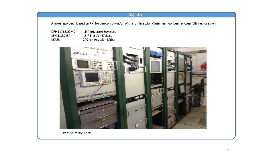
Objective A novel approach based on PXI for the consolidation of the Ion Injection Chain has now been successfully deployed on: DFH 11/12/21/42 KFH 31/32/34 KFA 28 LEIR Injection Bumpers LEIR Ejection Kickers CPS Ion Injection Kicker LEIR Kicker control platform 2
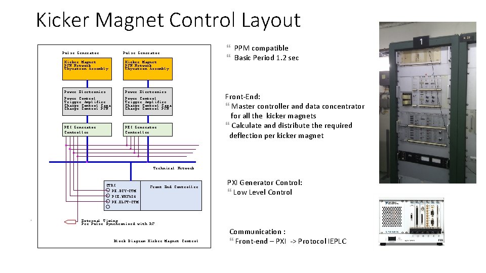
Kicker Magnet Control Layout Pulse Generator Kicker Magnet PFN Network Thyratron Assembly Power Electronics Power Control Trigger Amplifier Charge Control Capa Charge Control PFN PXI Generator Controller PPM compatible Basic Period 1. 2 sec Front-End: Master controller and data concentrator for all the kicker magnets Calculate and distribute the required deflection per kicker magnet Technical Network CTRI PX. SCY-CTM PIX. WKFA 28 PX. ELFT-CTM Front End Controller External Timing Pre Pulse Synchronized with RF Block Diagram Kicker Magnet Control PXI Generator Control: Low Level Control Communication : Front-end – PXI -> Protocol IEPLC
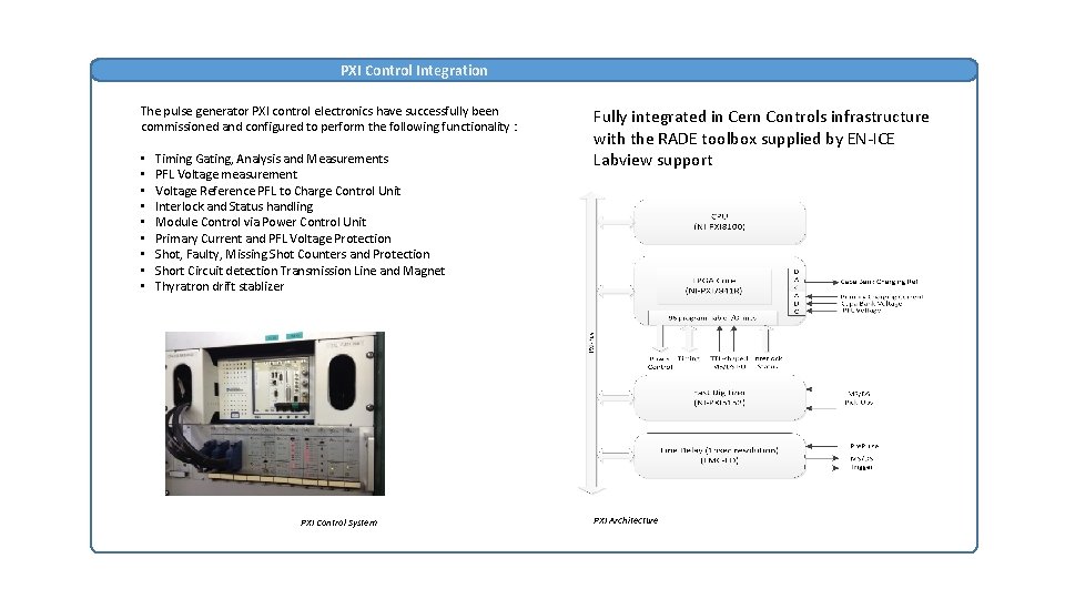
PXI Control Integration The pulse generator PXI control electronics have successfully been commissioned and configured to perform the following functionality : • • • Timing Gating, Analysis and Measurements PFL Voltage measurement Voltage Reference PFL to Charge Control Unit Interlock and Status handling Module Control via Power Control Unit Primary Current and PFL Voltage Protection Shot, Faulty, Missing Shot Counters and Protection Short Circuit detection Transmission Line and Magnet Thyratron drift stablizer PXI Control System Fully integrated in Cern Controls infrastructure with the RADE toolbox supplied by EN-ICE Labview support PXI Architecture
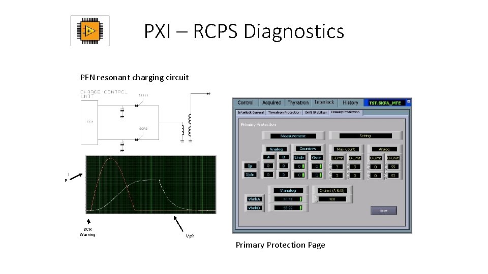
PXI – RCPS Diagnostics PFN resonant charging circuit I p SCR Warning Vpfn Primary Protection Page
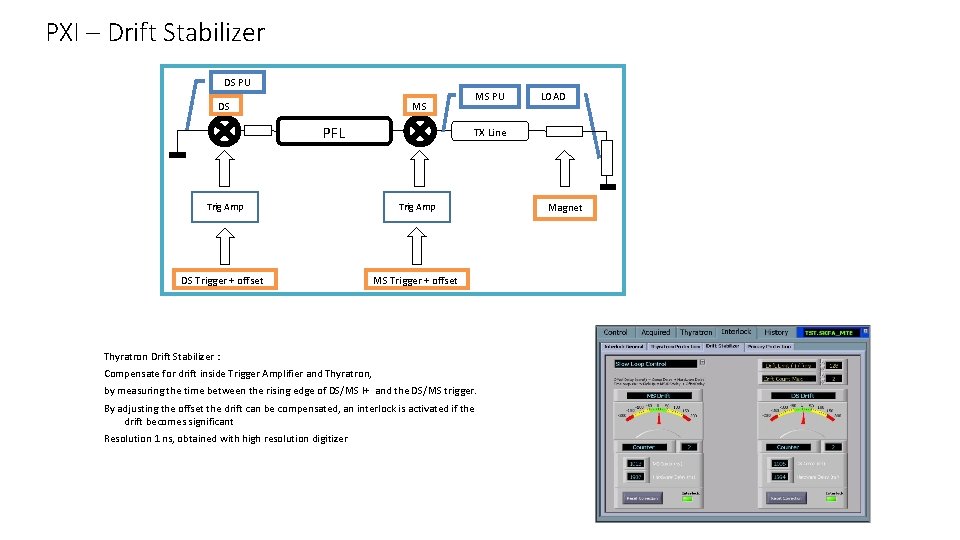
PXI – Drift Stabilizer DS PU DS MS PU MS PFL TX Line Trig Amp DS Trigger + offset MS Trigger + offset Thyratron Drift Stabilizer : Compensate for drift inside Trigger Amplifier and Thyratron, by measuring the time between the rising edge of DS/MS I+ and the DS/MS trigger. By adjusting the offset the drift can be compensated, an interlock is activated if the drift becomes significant Resolution 1 ns, obtained with high resolution digitizer LOAD Magnet
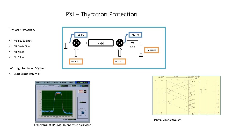
PXI – Thyratron Protection: DS PU • MS Faulty Shot • DS Faulty Shot • No MS I+ • No DS I+ MS PU PFN TX Line Magnet Dump S. Main S. With High Resolution Digitizer: • Short Circuit Detection Bewley-Lattice diagram Front-Panel of TPU with DS and MS Pickup Signal
- Slides: 7