
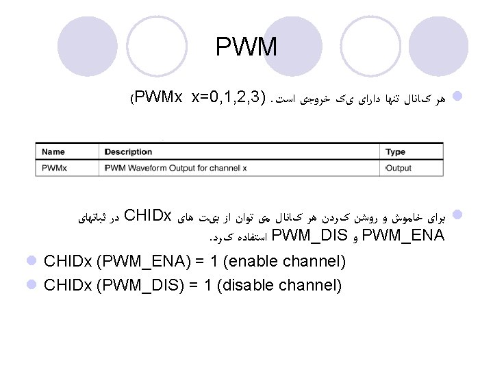
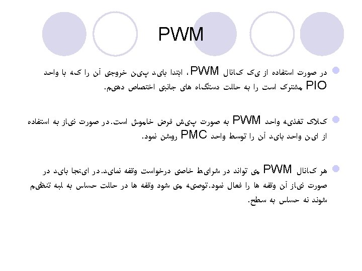
PWM controller block diagram PREA PREB Clock selector
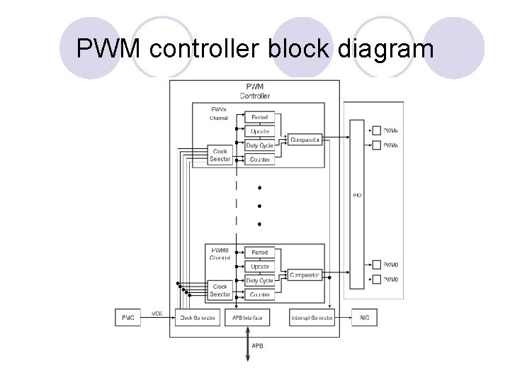
PWM controller block diagram
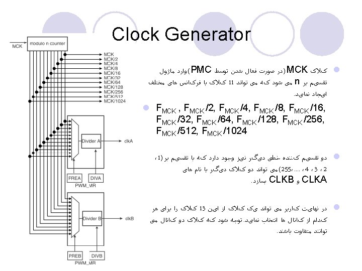
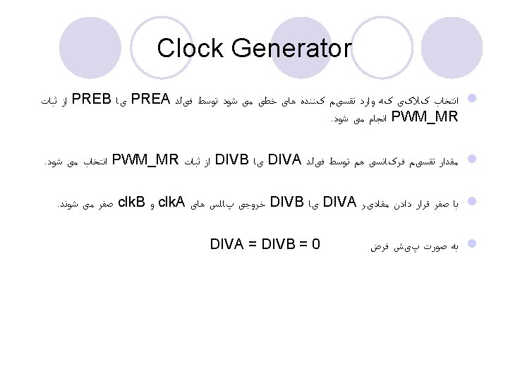
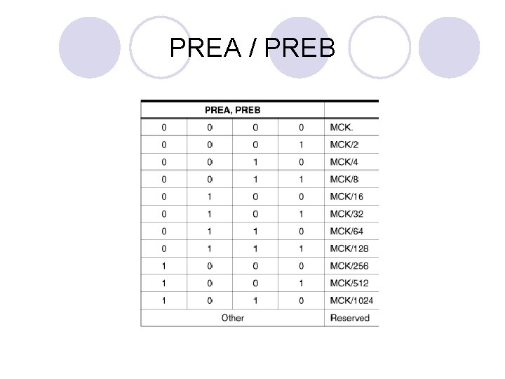
PREA / PREB
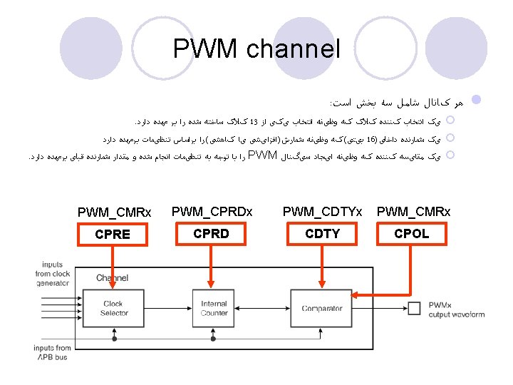
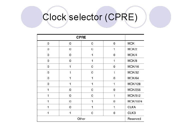
Clock selector (CPRE)
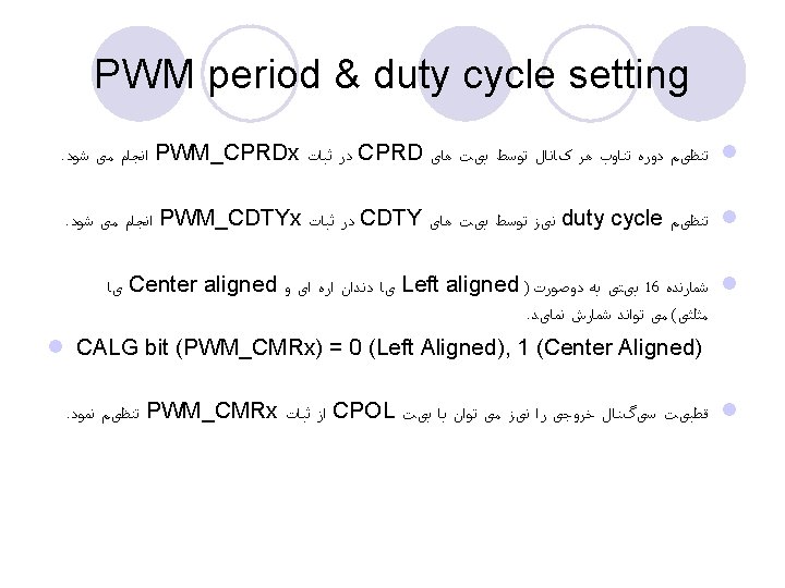
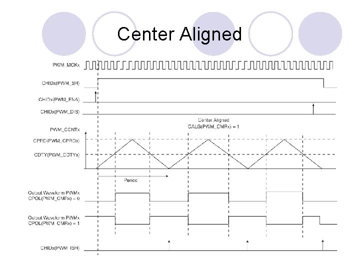
Center Aligned
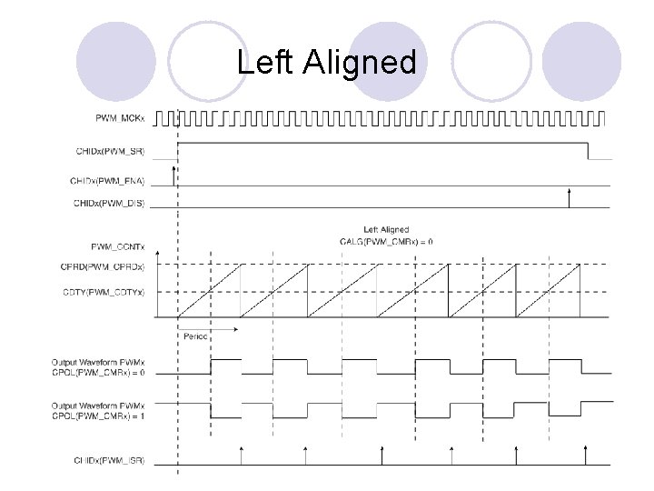
Left Aligned
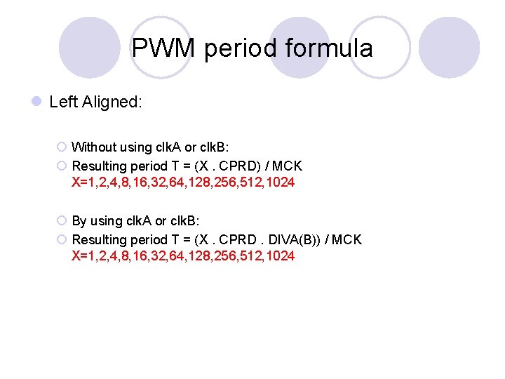
PWM period formula l Left Aligned: ¡ Without using clk. A or clk. B: ¡ Resulting period T = (X. CPRD) / MCK X=1, 2, 4, 8, 16, 32, 64, 128, 256, 512, 1024 ¡ By using clk. A or clk. B: ¡ Resulting period T = (X. CPRD. DIVA(B)) / MCK X=1, 2, 4, 8, 16, 32, 64, 128, 256, 512, 1024
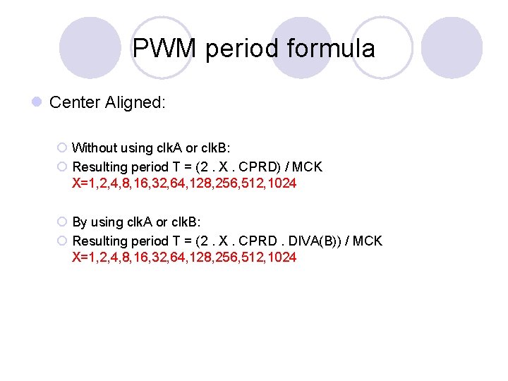
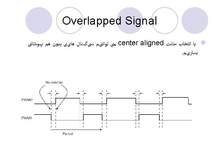
PWM period formula l Center Aligned: ¡ Without using clk. A or clk. B: ¡ Resulting period T = (2. X. CPRD) / MCK X=1, 2, 4, 8, 16, 32, 64, 128, 256, 512, 1024 ¡ By using clk. A or clk. B: ¡ Resulting period T = (2. X. CPRD. DIVA(B)) / MCK X=1, 2, 4, 8, 16, 32, 64, 128, 256, 512, 1024
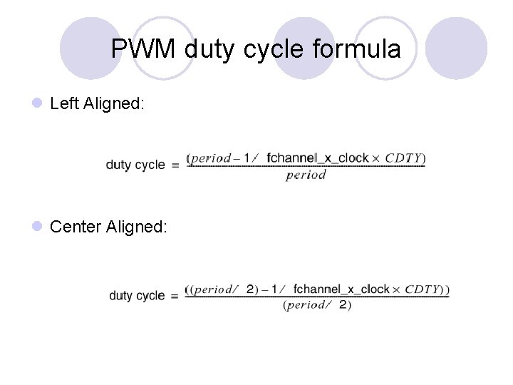
PWM duty cycle formula l Left Aligned: l Center Aligned:
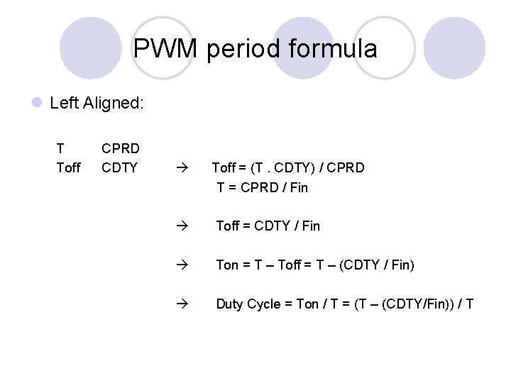
PWM period formula l Left Aligned: T Toff CPRD CDTY Toff = (T. CDTY) / CPRD T = CPRD / Fin Toff = CDTY / Fin Ton = T – Toff = T – (CDTY / Fin) Duty Cycle = Ton / T = (T – (CDTY/Fin)) / T
PWM l Waveforms are fixed at 0 when: ¡ CDTY = CPRD and CPOL = 0 ¡ CDTY = 0 and CPOL = 1 l Waveforms are fixed at 1 (once the channel is enabled) when: ¡ CDTY = 0 and CPOL = 0 ¡ CDTY = CPRD and CPOL = 1 l The waveform polarity must be set before enabling the channel. This immediately affects the channel output level. Changes on channel polarity are not taken into account while the channel is enabled.
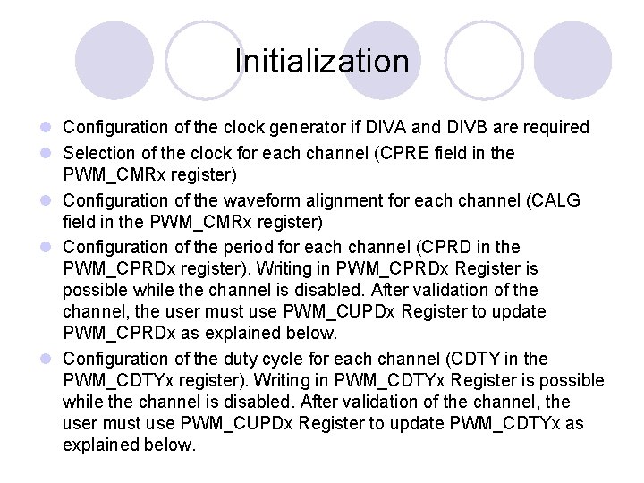
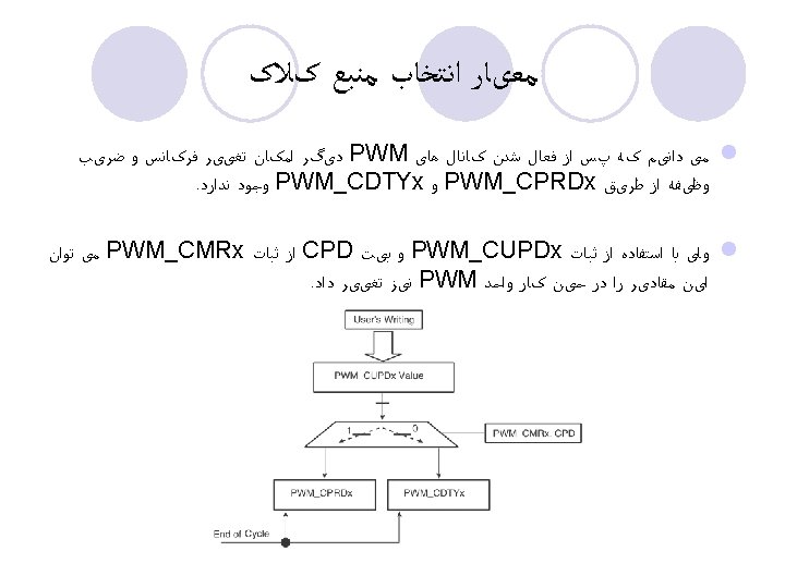
Initialization l Configuration of the clock generator if DIVA and DIVB are required l Selection of the clock for each channel (CPRE field in the PWM_CMRx register) l Configuration of the waveform alignment for each channel (CALG field in the PWM_CMRx register) l Configuration of the period for each channel (CPRD in the PWM_CPRDx register). Writing in PWM_CPRDx Register is possible while the channel is disabled. After validation of the channel, the user must use PWM_CUPDx Register to update PWM_CPRDx as explained below. l Configuration of the duty cycle for each channel (CDTY in the PWM_CDTYx register). Writing in PWM_CDTYx Register is possible while the channel is disabled. After validation of the channel, the user must use PWM_CUPDx Register to update PWM_CDTYx as explained below.
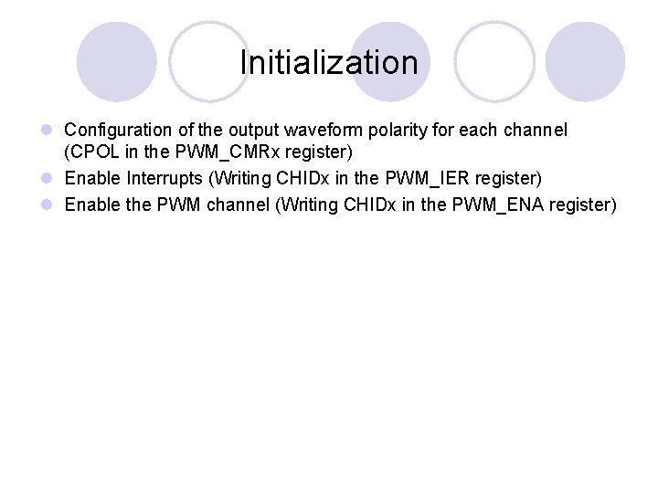
Initialization l Configuration of the output waveform polarity for each channel (CPOL in the PWM_CMRx register) l Enable Interrupts (Writing CHIDx in the PWM_IER register) l Enable the PWM channel (Writing CHIDx in the PWM_ENA register)

- Slides: 25