Purpose of Mohrs Circle Visual tool used to


- Slides: 13

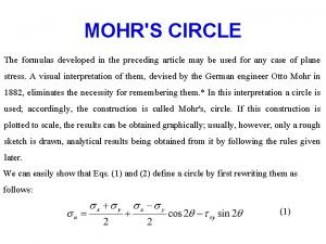
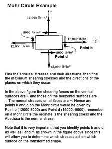
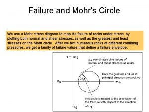
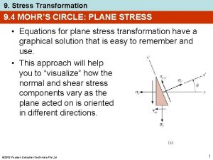
Purpose of Mohr’s Circle • Visual tool used to determine the stresses that exist at a given point in relation to the angle of orientation of the stress element. • There are 4 possible variations in Mohr’s Circle depending on the positive directions are defined.

Sample Problem y A particular point on the part x Some Part sy = -2 ksi sx = 6 ksi x & y orientation txy = 3 ksi

Mohr’s Circle t (CW) sy = -2 ksi x-axis (6 ksi, 3 ksi) sx = 6 ksi 2 6 txy = 3 ksi s Center of Mohr’s Circle 3 (-2 ksi, -3 ksi) y-axis 3

Mohr’s Circle t (CW) (savg, tmax) sy = -2 ksi x-face sx = 6 ksi (6 ksi, 3 ksi) txy = 3 ksi s s 2 savg = 2 ksi (-2 ksi, -3 ksi) y-face (savg, tmin) s 1

Mohr’s Circle (savg, tmax) (2 ksi, 5 ksi) t (CW) sy = -2 ksi x-face sx = 6 ksi (6 ksi, 3 ksi) R txy = 3 ksi s s 2 4 ksi y-face s 1 = savg + R = 7 ksi s 2 = savg – R = -3 ksi (savg, tmin) (2 ksi, -5 ksi) s 1

Mohr’s Circle t (CW) (savg, tmax) (2 ksi, 5 ksi) sy = -2 ksi x-face sx = 6 ksi (6 ksi, 3 ksi) 2 q txy = 3 ksi s 2 3 ksi 4 ksi y-face (savg, tmin) (2 ksi, -5 ksi) s s 1

Principle Stress t (CW) (savg, tmax) (2 ksi, 5 ksi) s 2 = -3 ksi x-face q = 18. 435° s 1 = 7 ksi Principle Stress Element s 2 Rotation on element is half of the rotation from the circle in same direction from x-axis (6 ksi, 3 ksi) 2 q 3 ksi 4 ksi (savg, tmin) (2 ksi, -5 ksi) s s 1

Shear Stress (savg, tmax) (2 ksi, 5 ksi) t (CW) x-face savg = 2 ksi f = 26. 565° tmax = 5 ksi savg = 2 ksi Maximum Shear Stress Element (6 ksi, 3 ksi) 2 f 2 q s 2 3 ksi 4 ksi y-face (savg, tmin) (2 ksi, -5 ksi) s s 1

Relationship Between Elements savg = 2 ksi tmax = 5 ksi sy = -2 ksi sx = 6 ksi f = 26. 565° q = 18. 435° txy = 3 ksi q + f = 18. 435 ° + 26. 565 ° = 45 ° savg = 2 ksi s 2 = -3 ksi s 1 = 7 ksi

What’s the stress at angle of 15° CCW from the x-axis? y A particular point on the part x V s = ? ksi Some Part s = ? ksi 15° t = ? ksi U & V new axes @ 15° from x-axis U x

Rotation on Mohr’s Circle t (CW) (savg, tmax) (s. U, t. U) x-face 30° s s 2 savg = 2 ksi y-face 15° on part and element is 30° on Mohr’s Circle (s. V, t. V) (savg, tmin) s 1

Rotation on Mohr’s Circle (savg, tmax) t (CW) (s. U, t. U) x-face R s. U = savg + R*cos(66. 869°) 66. 869° s. U = 3. 96 ksi s 2 s. V = savg – R*cos(66. 869°) s. V = 0. 036 ksi t. UV = R*sin(66. 869°) t. UV = 4. 60 ksi s savg = 2 ksi y-face (s. V, t. V) (savg, tmin) s 1

What’s the stress at angle of 15° CCW from the x-axis? y A particular point on the part x Some Part V s. V =. 036 ksi s. U = 3. 96 ksi U 15° x t = 4. 60 ksi
 Mohr's circle
 Mohrs circle equation
 Mohr
Mohr Mohr's type of test
 Vertical
 What is the point of tangency in circle j?
 Open or closed circle
 Circle a is tangent to circle b. true false
 Potter's wheel data cleaning tool
 Visual communication circle dance
 Circle time visual schedule
 Expanding expression tool visual
 Visual thinking tools
 Visual studio 2005
