
Pulse Detector Ramiro Duarte Clayton Greenbaum Frank Paynter
Pulse Detector Ramiro Duarte, Clayton Greenbaum Frank Paynter Prof. Betty Lise Anderson
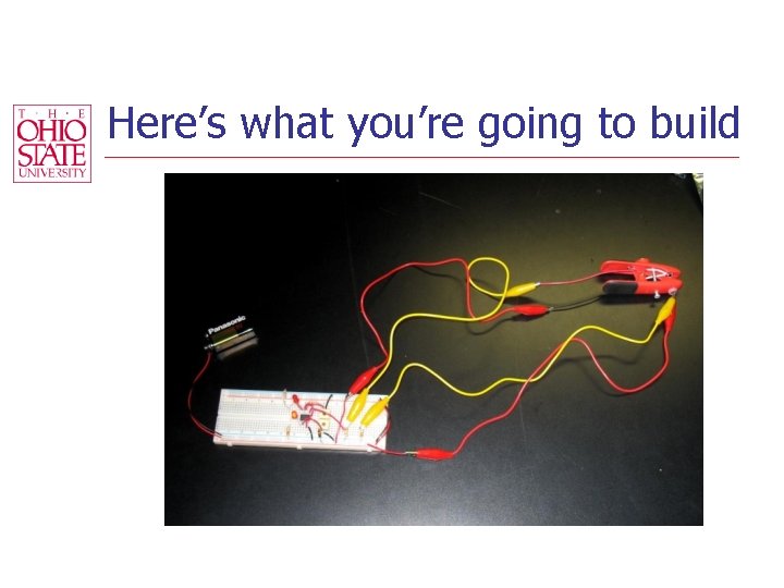
Here’s what you’re going to build
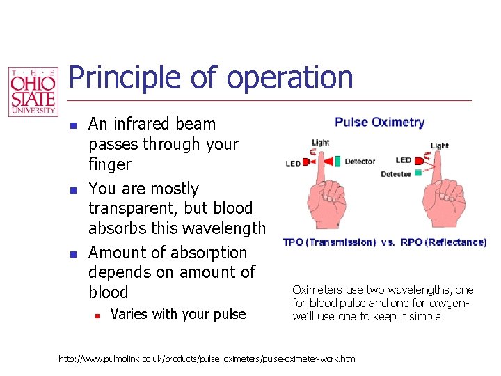
Principle of operation n An infrared beam passes through your finger You are mostly transparent, but blood absorbs this wavelength Amount of absorption depends on amount of blood n Varies with your pulse Oximeters use two wavelengths, one for blood pulse and one for oxygenwe’ll use one to keep it simple http: //www. pulmolink. co. uk/products/pulse_oximeters/pulse-oximeter-work. html
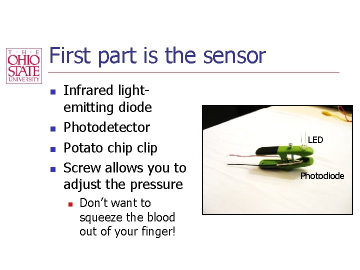
First part is the sensor n n Infrared lightemitting diode Photodetector Potato chip clip Screw allows you to adjust the pressure n Don’t want to squeeze the blood out of your finger! LED Photodiode
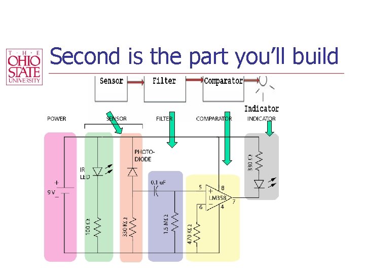
Second is the part you’ll build

Need to learn some things n n How to read an electrical schematic What parts we’re using How to design the display How to build the display
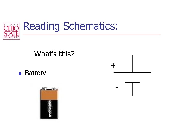
Reading Schematics: What’s this? n Battery
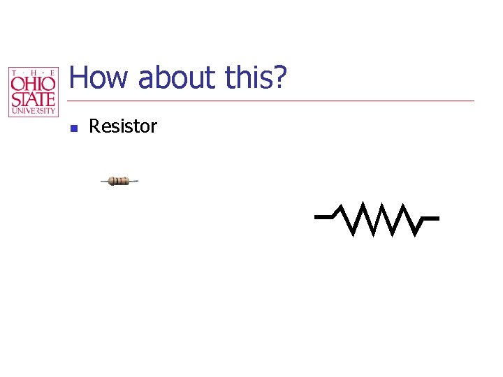
How about this? n Resistor
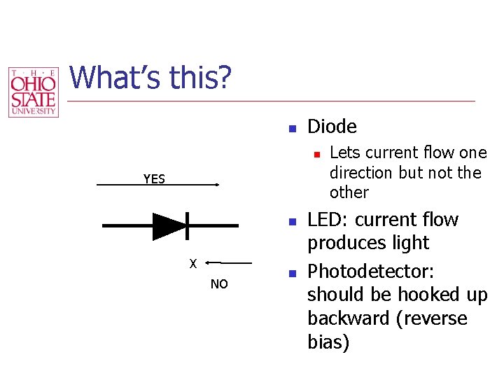
What’s this? n Diode n YES n X NO n Lets current flow one direction but not the other LED: current flow produces light Photodetector: should be hooked up backward (reverse bias)
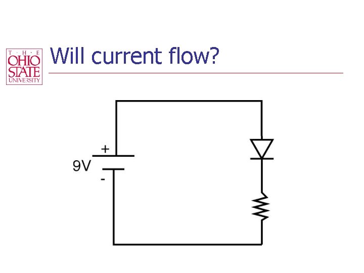
Will current flow?
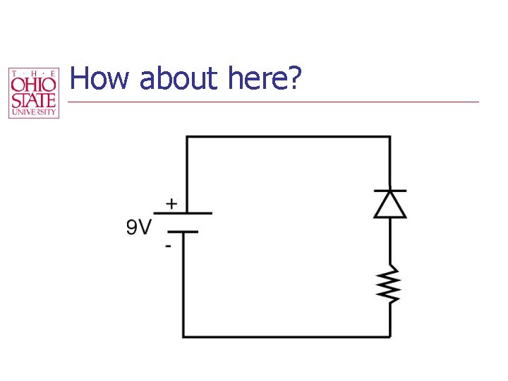
How about here?
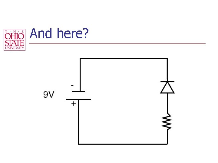
And here?
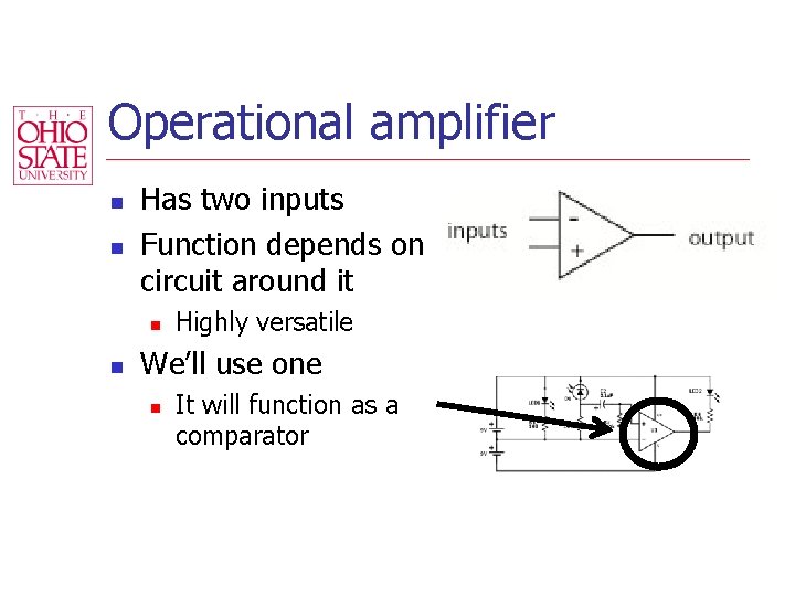
Operational amplifier n n Has two inputs Function depends on circuit around it n n Highly versatile We’ll use one n It will function as a comparator
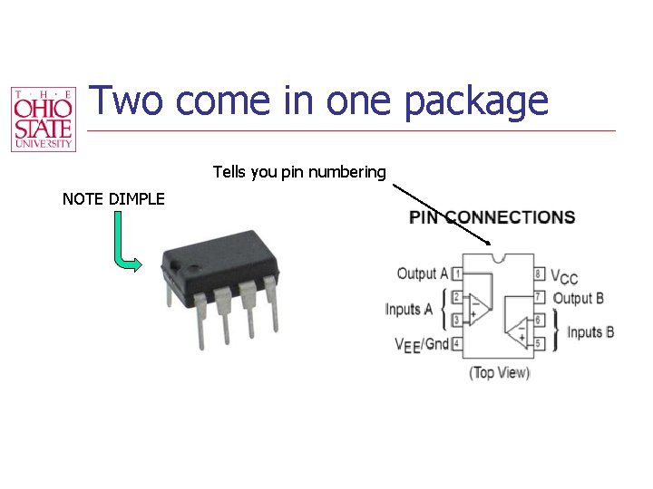
Two come in one package Tells you pin numbering NOTE DIMPLE
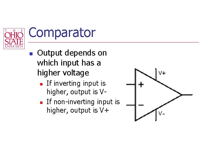
Comparator n Output depends on which input has a higher voltage n n If inverting input is higher, output is VIf non-inverting input is higher, output is V+
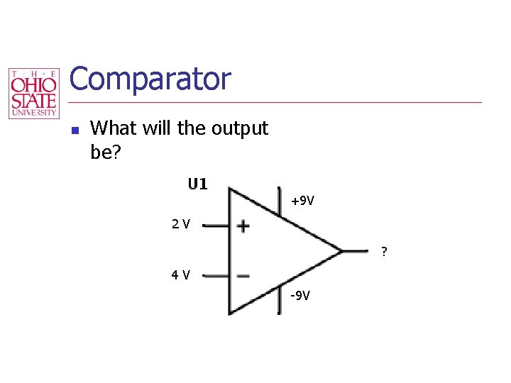
Comparator n What will the output be? +9 V 2 V ? 4 V -9 V
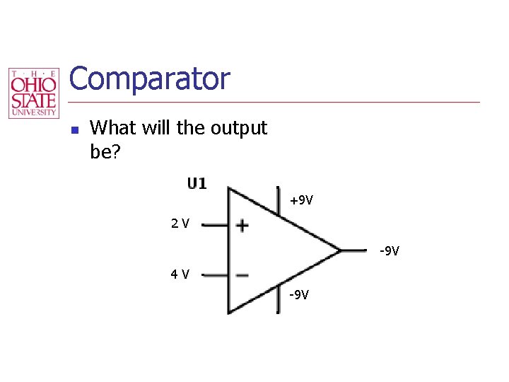
Comparator n What will the output be? +9 V 2 V -9 V 4 V -9 V
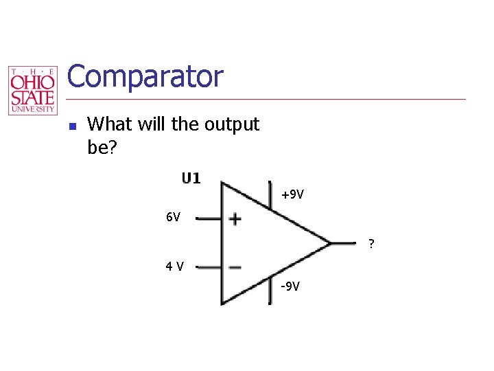
Comparator n What will the output be? +9 V 6 V ? 4 V -9 V
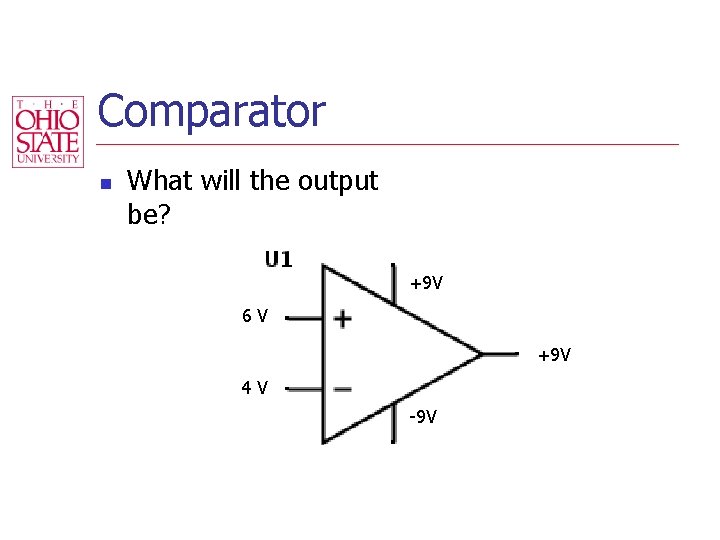
Comparator n What will the output be? +9 V 6 V +9 V 4 V -9 V
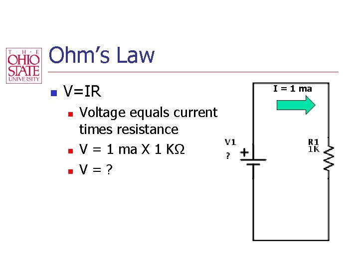
Ohm’s Law n V=IR n n n Voltage equals current times resistance V = 1 ma X 1 KΩ V=? I = 1 ma
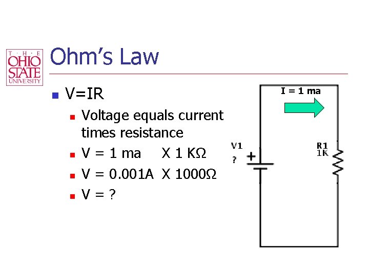
Ohm’s Law n V=IR n n Voltage equals current times resistance V = 1 ma X 1 KΩ V = 0. 001 A X 1000Ω V=? I = 1 ma
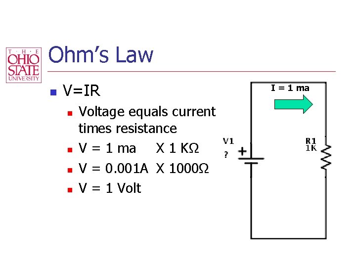
Ohm’s Law n V=IR n n Voltage equals current times resistance V = 1 ma X 1 KΩ V = 0. 001 A X 1000Ω V = 1 Volt I = 1 ma
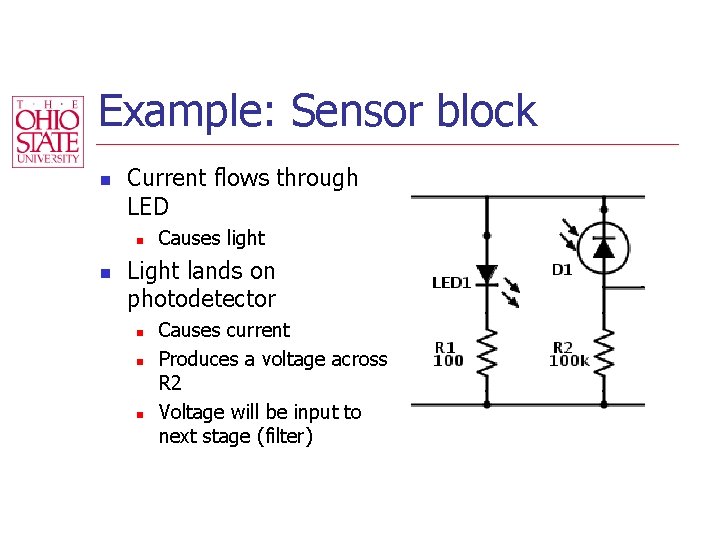
Example: Sensor block n Current flows through LED n n Causes light Light lands on photodetector n n n Causes current Produces a voltage across R 2 Voltage will be input to next stage (filter)
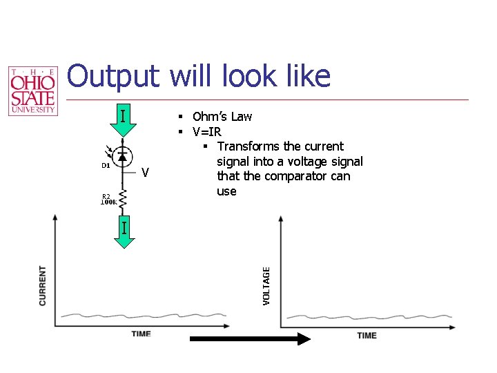
Output will look like I V § Ohm’s Law § V=IR § Transforms the current signal into a voltage signal that the comparator can use VOLTAGE I
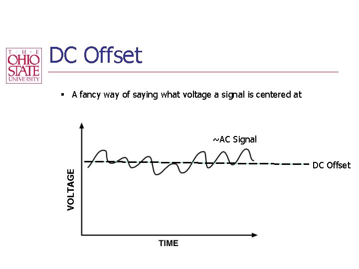
DC Offset § A fancy way of saying what voltage a signal is centered at VOLTAGE ~AC Signal DC Offset
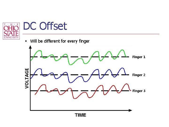
DC Offset § Will be different for every finger
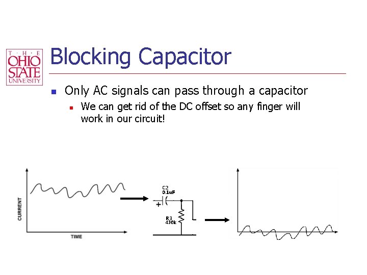
Blocking Capacitor n Only AC signals can pass through a capacitor n We can get rid of the DC offset so any finger will work in our circuit!
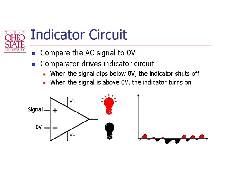
Indicator Circuit n n Compare the AC signal to 0 V Comparator drives indicator circuit n n Signal 0 V When the signal dips below 0 V, the indicator shuts off When the signal is above 0 V, the indicator turns on
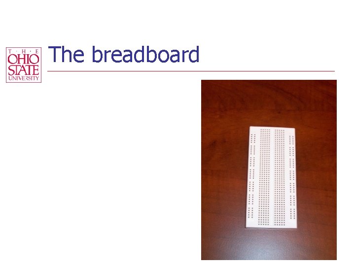
The breadboard
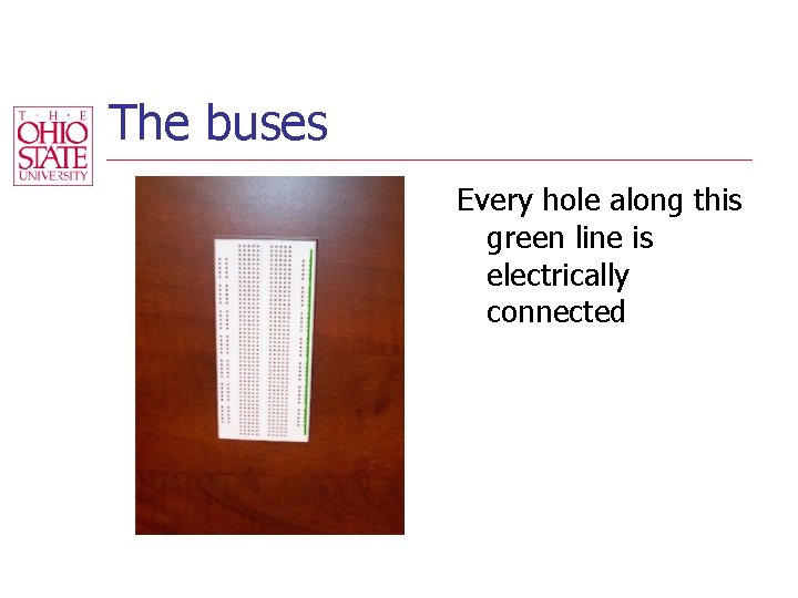
The buses Every hole along this green line is electrically connected
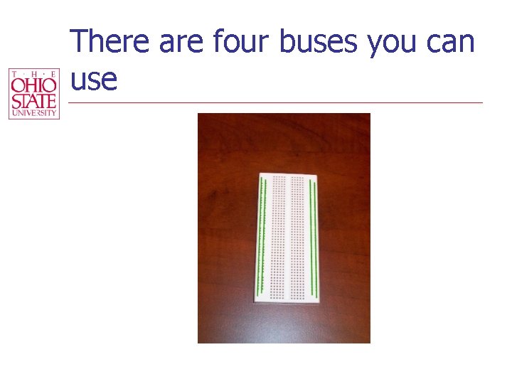
There are four buses you can use

All rows connected too
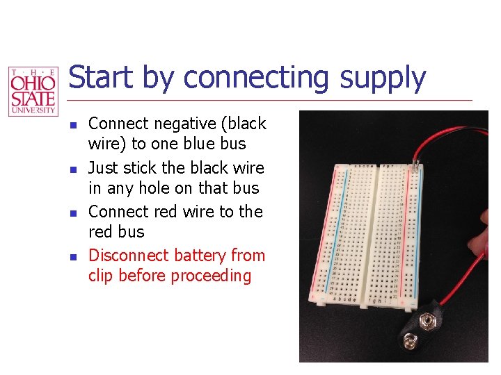
Start by connecting supply n n Connect negative (black wire) to one blue bus Just stick the black wire in any hole on that bus Connect red wire to the red bus Disconnect battery from clip before proceeding
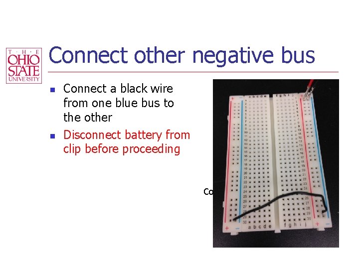
Connect other negative bus n n Connect a black wire from one blue bus to the other Disconnect battery from clip before proceeding Common Bus Negative Bus Positive Bus
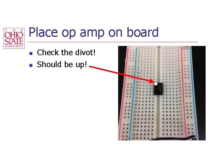
Place op amp on board n n Check the divot! Should be up!
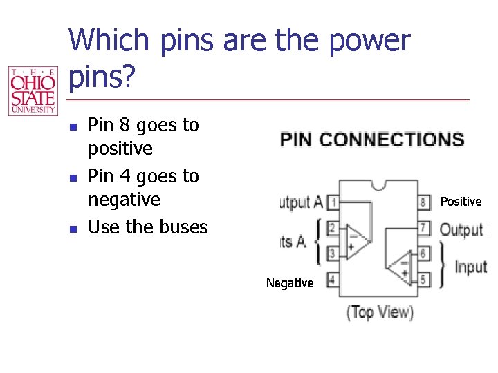
Which pins are the power pins? n n n Pin 8 goes to positive Pin 4 goes to negative Use the buses Positive Negative
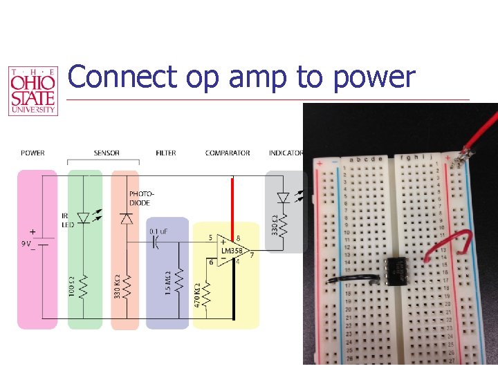
Connect op amp to power
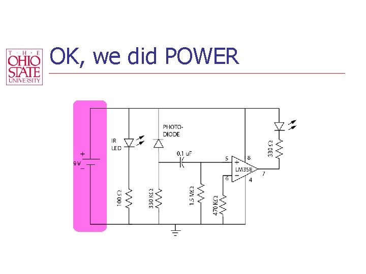
OK, we did POWER
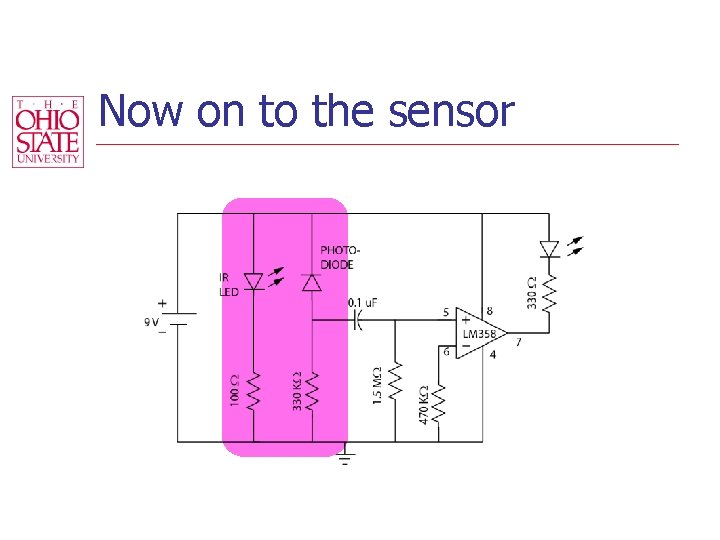
Now on to the sensor
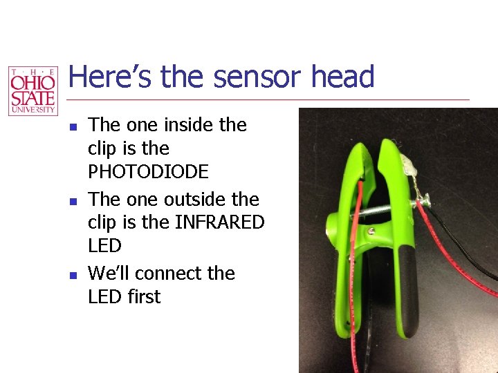
Here’s the sensor head n n n The one inside the clip is the PHOTODIODE The one outside the clip is the INFRARED LED We’ll connect the LED first
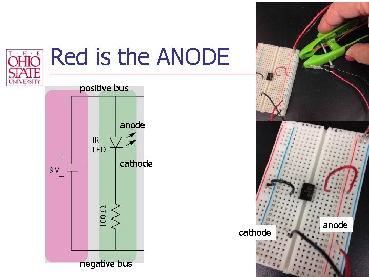
Red is the ANODE positive bus anode cathode negative bus anode
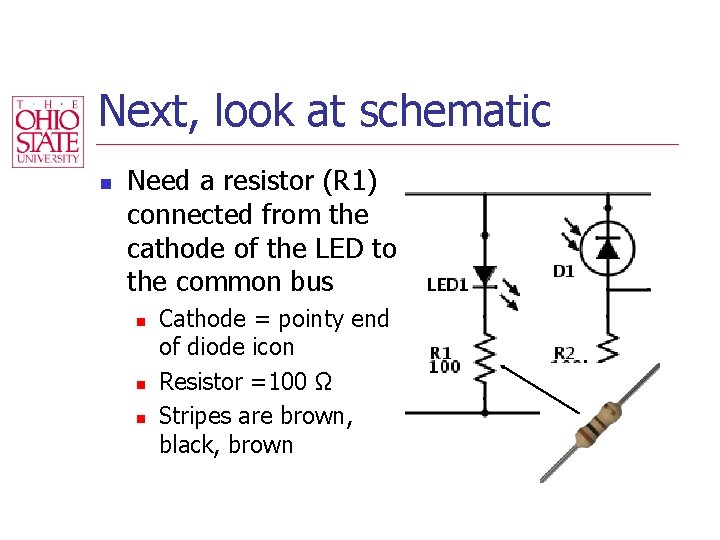
Next, look at schematic n Need a resistor (R 1) connected from the cathode of the LED to the common bus n n n Cathode = pointy end of diode icon Resistor =100 Ω Stripes are brown, black, brown
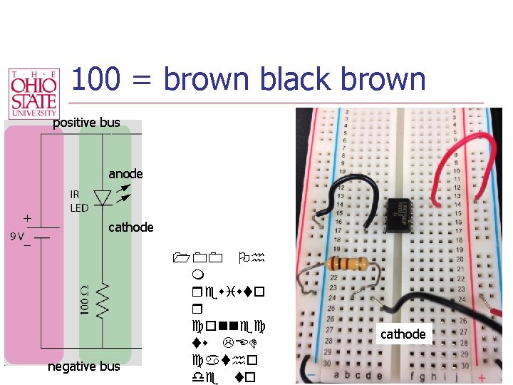
100 = brown black brown positive bus anode cathode negative bus 100 Oh m resisto r connec ts LED catho de to cathode
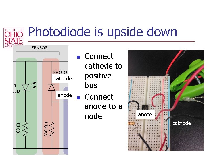
Photodiode is upside down n cathode anode n Connect cathode to positive bus Connect anode to a node anode cathode
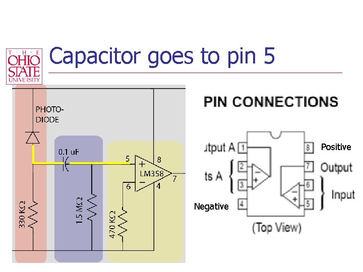
Capacitor goes to pin 5 Positive Negative
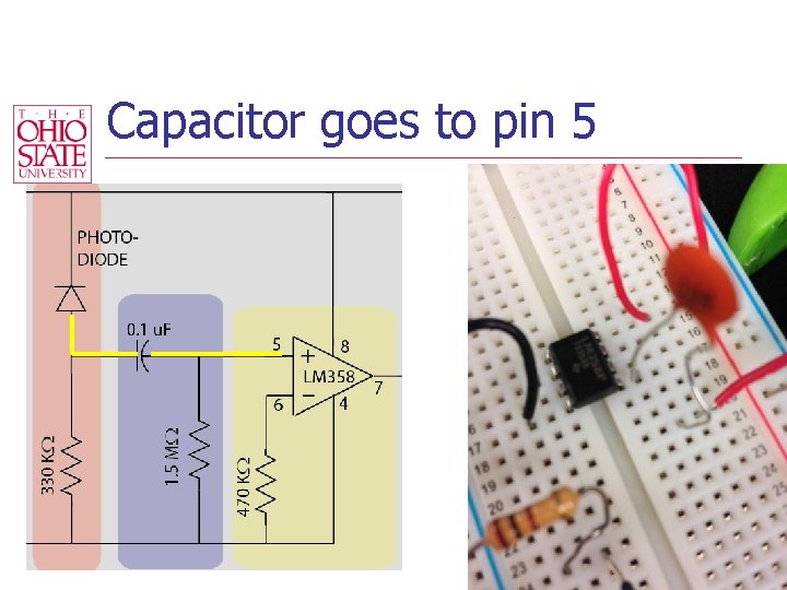
Capacitor goes to pin 5
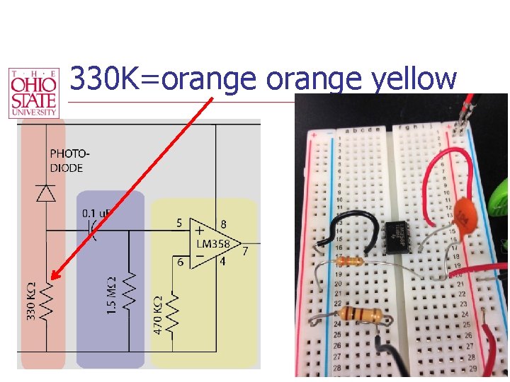
330 K=orange yellow
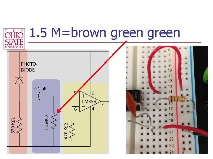
1. 5 M=brown green
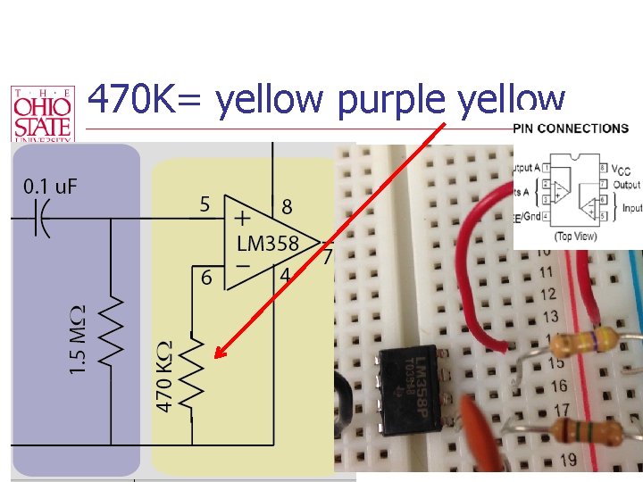
470 K= yellow purple yellow
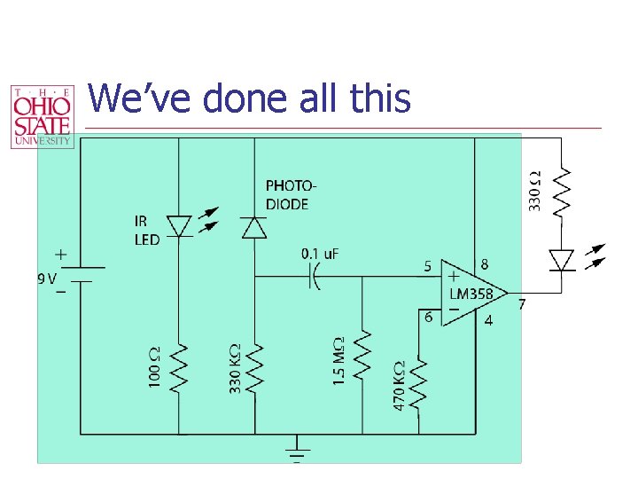
We’ve done all this
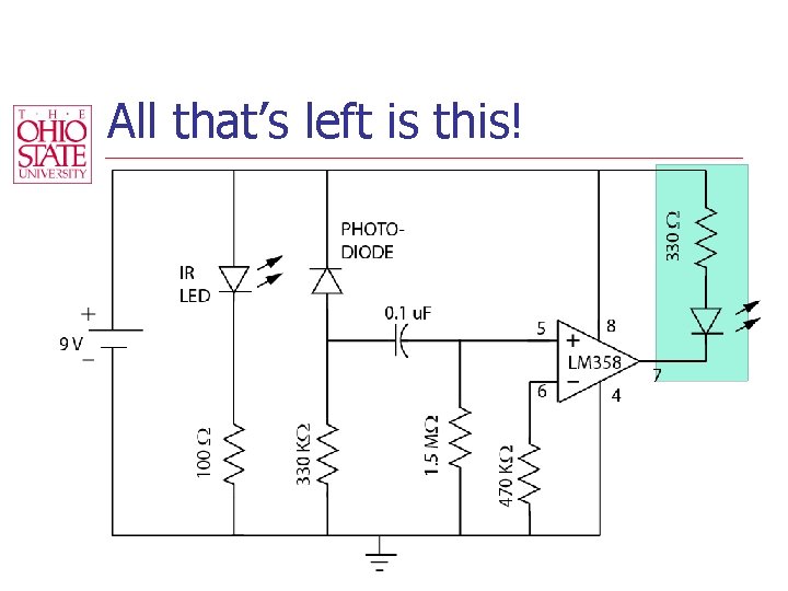
All that’s left is this!
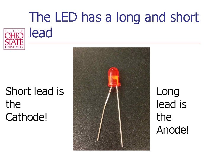
The LED has a long and short lead Short lead is the Cathode! Long lead is the Anode!
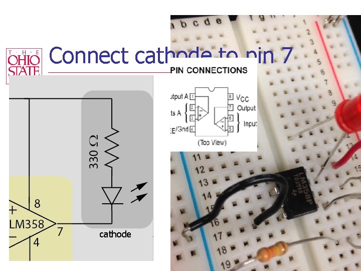
Connect cathode to pin 7 cathode
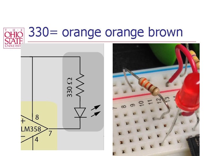
330= orange brown
To operate n Put clip on tip of finger n n If everything is working correctly, moving your finger in the clip should cause the LED to blink. If the LED never, ever blinks there is a problem with your circuit or one of the parts. (E. g. dead battery) Adjust screw to make pressure gentle Hold very still Light should begin to blink with your pulse n If you see a double blink with each pulse, you can move the clip to a thicker part of your finger (try a joint)
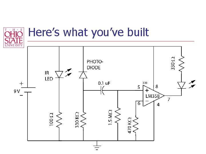
Here’s what you’ve built 330
- Slides: 56