PTT 350 SEPARATION ENGINEERING MEMBRANE FILTRATION CO 2
 Mohd Sharizan Md Sarip")
PTT 350 -SEPARATION ENGINEERING MEMBRANE FILTRATION (CO 2) Mohd Sharizan Md Sarip

Contents of this topic • Classify several types of membrane separation processes. • Examine types of membranes and permeabilities constant for binary/multicomponent gases mixtures separation. • Determine the osmotic pressure, water and solute flux, and overall performance in a reverse-osmotic unit. • Compare the ultrafiltration, microfiltration and nanofiltration based membrane process.

WHAT IS A MEMBRANE? üA membrane is a thin layer of semi-permeable material that is used for solute separation as transmembrane pressure is applied across the membrane. üThe degree of selectivity is largely based on the membrane charge and porosity. üMembranes with symmetric pores are more uniform, while asymmetric pores have variable pore diameters.

CLASSIFICATION OF MEMBRANE PROCESSES 1. Gas diffusion in porous solid • Gas phase present in both sides of membrane (microporous solid) • Rate of molecular diffusion of various gas molecules depend on the pore sizes and molecular weights. 2. Liquid permeation or dialysis • One liquid phase diffuse readily due to concentration differences through a porous membrane to a second liquid (or vapor) phase 4

5 Cont’ 3. Gas permeation in a membrane • Membrane is usually a polymer (rubber, polyamide and not a porous solid). • Zeolite • Example- helium being separated from natural gas 4. Reverse osmosis • A reverse pressure difference is imposed which causes the flow of solvent to reverse. • Example- desalination of seawater

Cont’ 5. Ultrafiltration membrane process • Membrane discriminates on the basis of molecular size, shape or chemical structure. • Separates high molecular weight solutes (proteins, polymers and colloid minerals) 6. Microfiltration membrane process • Pressure-driven flow through the membrane is used to separate micron-size particles from fluids. • The particles are usually > in ultrafiltration

7 cont’ 7. Gel permeation chromatography • The porous gel retards diffusion of the high molecular weight solutes. • Analyze the complex chemical structure and purify the desired components

SELECTED MEMBRANE AND APPLICATION üUtilizes a membrane to separate particles that are much larger than the solvent used üTypes of membrane filtration : - Reverse Osmosis (RO) - Nano filtration (NF) - Ultrafiltration (UF) - Microfiltration (MF) üWidely used in separation of macromolecules and ion (protein, glucose, virus and bacteria)

REVERSE OSMOSIS üOnly remove some suspended materials larger than 0. 001 μm üThe process eliminates the dissolved solids, bacteria, viruses and other germs contained in the water üOnly water molecules allowed to pass via very big pressure üAssymmetric type membranes (decrease the driving pressure of the flux) üAlmost all membranes are made of polymers, cellulosic acetate and matric polyamide types rated at 96%-99% Na. Cl rejection

REVERSE OSMOSIS üExtensive Applications: üPotable water from sea or brackish water üUltrapure water food processing and electronic industries üPharmaceutical grade water üWater for chemical, pulp & paper industry üWaste treatment

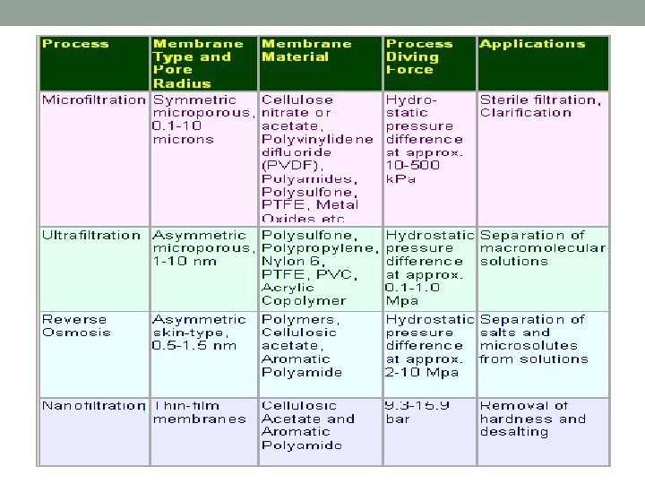
MICROFILTRATION ü Microfiltration membranes have the most open pore sizes of all polymeric membranes. ü With a pore size range of 0. 1 to 10μm, microfiltration membranes are capable of separating large suspended solids such as colloids, particulates, fat, and bacteria, while allowing sugars, proteins, salts, and low molecular weight molecules pass through the membrane. ü Microfiltration membranes feature an asymmetric pore structure, with tighter surface pores to control rejection, and more open macrovoids in the membrane cross section, in order to optimize flux.

MICROFILTRATIO N

MICROFILTRATION Applications: Dairy ü Fat / microbial removal in Whey Protein Concentrate / Isolate ü Casein / Whey fractionation ü Clarification of fermentation broths ü Microbial removal, clarification Food/Beverage ü Plant extract clarification ü Gelatin clarification ü Corn wet milling Industrial/Wastewater Treatment ü Industrial process wastewater treatment

ULTRAFILTRATION ü Ultrafiltration membranes are capable of separating larger materials such as colloids, particulates, fats, bacteria, and proteins, while allowing sugars, and other low molecular weight molecules to pass through the membrane. ü With a pore size range between 0. 01 to 0. 1µm, ultrafiltration membrane pore sizes fall between that of nanofiltration and microfiltration. ü UF membranes typically operate between 50 – 120 Psi (3. 4 – 8. 3 bar) and are dependent on transmembrane pressure to drive the separation process. ü Other polymeric ultrafiltration membrane characteristics include robust chemical and temperature resistance, and low fouling tendencies if proper pretreatment is employed.

ULTRAFILTRATION

ULTRAFILTRATION Applications: Industrial Process and Wastewater ü Oil Removal in Wastewater Treatment Dairy ü Whey Protein Concentrate/Isolate concentration ü Milk protein concentration/standardizing ü Brine clarification ü Casein/Whey Fractionation Biotech / Pharmaceutical ü Enzyme/protein concentration ü Endotoxin & pyrogen removal ü Antibiotics production ü Blood plasma processing Food & Beverage ü Gelatin concentration & purification ü Plant extract processing ü Corn wet milling ü Fruit juice concentration Automotive / Industrial ü Electrocoat painting ü Industrial wastewater treatment

NANOFILTRATION ü Nanofiltration is a separation process characterized by organic, thin-film composite membranes with a pore size range of 0. 0001 -0. 001μm. ü With a pore size between 0. 0001 -0. 001μm, nanofiltration membranes allow water and some salts to pass through the membrane while retaining multivalent ions, low molecular weight molecules, sugars, proteins, and other organic compounds. ü Unlike reverse osmosis (RO) membranes, which reject all solutes, NF membranes can operate at lower pressures and offer selective solute rejection based on both size and charge.

NANOFILTRATION Cellulosic acetate and aromatic polyamide type membranes (salt rejections; 95% for divalent salts to 40% for monovalent salts)

NANOFILTRATION Industrial/Wastewater Treatment ü Removal of natural organic matter in water and wastewater treatment ü Reduction of hardness in water purification ü Sulfate removal from seawater and chemical processes ü Desalting of process streams in various industries Dairy ü Lactose and whey demineralization in dairy processing ü Lactose and whey concentration

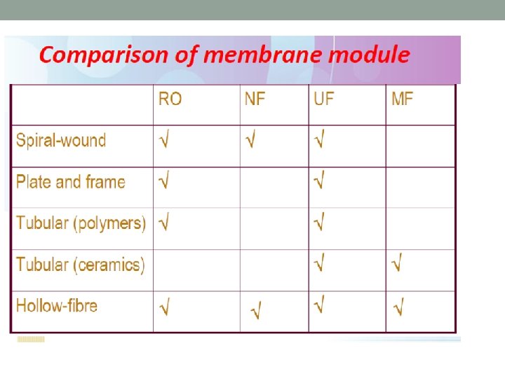
MEMBRANE CONFIGURATIONS üThis refers to the packing of the membrane in the module so that it can be installed in the system. üCommon configurations include : - Plate and Frame - Tubular - Spiral Wound - Hollow Fine Fibre

Plate and Frame Membranes

Plate and Frame Membranes Description Plate and Frame membrane systems utilize membranes laid on top of a plate-like structure, which in turn is held together by a frame-like support. There are two types of plate and frame membrane configurations, dead end and cross flow. In dead end plate and frame systems, the feed solution flows perpendicular into the membrane, while cross flow systems are made so that the flow is tangential to the membrane wall. How it works Because the flow is perpendicular to the membrane, dead end plate and frame membrane separation works through a process called cake filtration. Cake filtration starts when the feed solution passes through the filter plates and creates a buildup of solids on the filter surface. This buildup, or cake layer, reduces the effective pore size opening of the filter and helps improve the filtration of the feed solution. For cross flow plate and frame membrane systems, fouling of the membrane is significantly less because the flow is tangential and does not require use of the cake filtration system. It works on the basic principles of cross flow where feed enters on one side of the plated membrane and concentrate collects on the other end of the plate. Permeate travels through the membrane and collects on the inside of the supporting plate. Disadvantages Low packing density is one major problem for plate and frame membrane systems. Low efficiency compared to other configurations, and high pressure drop, are other problems that plague plate and frame systems as well. Advantages Easy separation of solids from water and easy removal/cleaning of filter surfaces are the main advantages of plate and frame membrane systems. Depending on the application, plate and frame membrane modules can be easy to use and the overall cost of the system can be low.
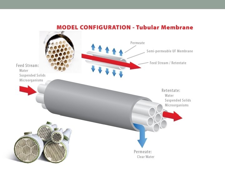

Tubular Membranes Description Tubular membrane modules are tube-like structures with porous walls. Tubular modules work through tangential cross-flow, and are generally used to process difficult feed streams such as those with high dissolved solids, high suspended solids, and/or oil, grease, or fats. How it works Tubular modules consist of a minimum of two tubes; the inner tube, called the membrane tube, and the outer tube, which is the shell. The feed stream goes across the length of the membrane tube and is filtered out into the outer shell while concentrate collects at the opposite end of the membrane tube. Disadvantages Low packing density and large size are disadvantages of tubular modules. Packing density of tubular modules is higher than plate and frame systems but lower than capillary, hollow fiber, and spiral wound elements. Because of the large inner diameter of the tubular modules, flow requirements are higher than those of other system configurations. Advantages Tubular systems have less fouling compared to plate and frame systems, and a similar amount of fouling when compared to spiral and capillary. Tubular systems allow for robust cleaning methods such as the use of harsh chemicals, backwash, and even mechanical cleaning which might not be available for other system configurations.

Spiral Wound Membranes

Spiral Wound Membranes Description Spiral-wound filters utilize flat-sheet membranes, feed spacers, and permeate spacers wrapped around a hollow tube called the permeate tube. Spiral wound elements utilize cross flow technology, and because of its construction, can easily be created in different configurations with varying length, diameter, and membrane material. How it works Feed travels through the flow channels tangentially across the length of the element. Filtrate will then pass across the membrane surface into the permeate spacer, where it is carried down the permeate spacer towards the permeate tube. The feed then becomes concentrated at the end of the element body. Disadvantages Spiral element fouling is greater than fouling in tubular filtration processes. Spiral elements also cannot handle mechanical cleaning like tubular elements, and contain lower packing density than hollow fiber. Advantages Spiral-wound elements come in multiple configurations with different spacers, membrane types, lengths, and diameters that allow it to fit multiple applications. These elements have a very high packing density, surpassing the packing density of plate and frame, tubular, and capillary configurations. Spiral membranes allow for easy cleaning through cleaning in place and backwash.

Hollow Fiber Membranes

Hollow Fiber Membranes Description Hollow fiber filtration utilizes numerous long porous filaments packed inside a body. Each filament is very narrow in diameter and very flexible. Hollow fiber can find uses in all types of filtration, ranging from microfiltration to reverse osmosis. How it works Hollow fiber filtration works on the same principle as tubular filtration, but utilizes a small tube diameter which allows for flexibility. Disadvantages Irreversible fouling and easy breakage are the main problems concerning hollow fiber filtration. Because of the flexibility of the fibers, they are more likely to break when under high strain compared to other methods of filtration such as tubular or spiral wound elements. Advantages Hollow fiber features very high packing density because of the small strand diameter. Because of the flexibility of the strands, certain filter configurations are possible that cannot be achieved in other filtration configurations.

Permeation Membrane Process/solid following fick laws Liquid phase 32 Gas phase c 1= bulk liquid or gas phase concentration of the diffusing solute A (kg mol A/m 3) c 1 i= concentration of A in the fluid just adjacent to the solid c 1 i. S= concentration of A in the solid at the surface Flux kc 1 and kc 2= mass transfer coefficient (m/s) (Transport Processes and Separation Processes Principles, Geankoplis, Pearson)

GAS PERMEATION MEMBRANE PROCESS 33 Equilibrium relation between the solid and gas phases: Flux for gas S = Solubility of A in m 3 (STP) / atm. m 3 solid H = Equilibrium relation in kg mol/m 3

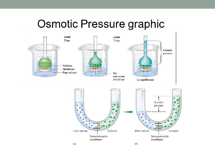
Osmotic pressure of solutions, π n= number of kg mol of solute Vm= volume of pure solvent water in m 3 R=gas law constant (82. 057 x 10 -3 m 3. atm /kg mol. K) (Transport Processes and Separation Processes Principles, Geankoplis, Pearson)

Osmotic pressure of solutions • Experimental data shows that the osmotic pressure π of a solution is proportional to the concentration of the solute and temperature T • Van’t Hoff originally showed that the relationship is similar to that for pressure of an ideal gas • For example, for dilute water solutions, (1) n: number of kg mol of solute, Vm: volume of pure solvent water in m 3 associated with n kg mol of solute, R: gas law constant 82. 057 x 10 -3 m 3·atm/kg mol·K, T: temperature in K. • If a solute exists as two or more ions in solution, n represents the total number of ions • For more concentrated solutions, Eq. (1) is modified using the osmotic coefficient Φ, which is the ratio of the actual osmotic pressure π to the ideal π calculated from the equation

Flux Equation for Reverse Osmosis Diffusion-type models • For diffusion type membranes, the steady-state equations governing the transport of solvent and solute are to a first approximation. • For the diffusion of the solvent through the membrane, (2) (3) • where Nw is the solvent (water) flux in kg/s·m 2; Pw the solvent membrane permeability, kg solvent/s·m·atm; Lm the membrane thickness, m; Aw the solvent permeability constant, kg solvent/s·m 2·atm; ΔP = P 1 - P 2 (hydrostatic pressure difference with P 1 pressure exerted on feed and P 2 on product solution), atm; and Δπ = π1 - π2 (osmotic pressure of feed solution - osmotic pressure of product solution), atm.

Flux Equation for Reverse Osmosis • For the diffusion of the solute through a membrane, an approximation for the flux of the solute is (4) (5) • where Ns is the solute (salt) flux in kg solute/s·m 2; Ds the diffusivity of solute in membrane, m 2/s; Ks = cm/c (distribution coefficient), concentration of solute in membrane/concentration of solute in solution; As is the solute permeability constant, m/s; c 1 the solute concentration in upstream or feed (concentrate) solution, kg solute/m 3; and c 2 the solute concentration in downstream or product (permeate) solution, kg solute/m 3. The distribution coefficient Ks is approximately constant over the membrane.

Flux Equation for Reverse Osmosis • Making a material balance at steady state for the solute, the solute diffusing through the membrane must equal the amount of solute is leaving in the downstream or product ( permeate) solution: (6) • where cw 2 is the concentration of solvent in stream 2 (permeate), kg solvent/m 3. If the stream 2 is dilute in solute, cw 2 is approximately the density of the solvent. • In reverse osmosis, the solute rejection R is defined as the ratio concentration difference across the membrane divided by the bulk concentration on the feed or concentrate side (fraction of solute remaining in the feed stream): (7)

Flux Equation for Reverse Osmosis • This can be related to the flux equation as follows, by first substituting Eq. (2) and (4) into (6) to eliminate Nw and Ns in Eq. (6) • Then, solving for c 2/c 1 and substituting this result to Eq. (7) (8) (9) where B is in atm-1

Thank You
- Slides: 40