
PTRT 1321 OilField Hydraulics Chapter 5 Blowout Prevention
PTRT 1321 Oil-Field Hydraulics Chapter 5 Blowout Prevention Equipment Oil and Gas Technology Program
BOP’s Generally reliable Must be properly operated and maintained Designed to close in the well when a kick occurs Most can be quickly opened and closed hydraulically • Hydraulic energy stored in accumulator • Two types usually included in a stack • • – Annular preventers (at least one) – Ram preventers (at least two usually three or more) • Spools included to create vertical space for connecting lines Oil and Gas Technology Program
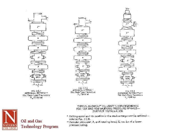
Stack Configurations • API RP-53, Blowout Prevention Equipment Systems – – – A – annular blowout preventer G – rotating head R – single ram preventer (blind or pipe rams) Rd – double ram preventer Rt – triple ram preventer S – spool with side outlet connections for choke and kill lines • M stands for 1000 psi plus the bore size is usually indicated as well • Each well must be considered on an individual basis Oil and Gas Technology Program
Oil and Gas Technology Program
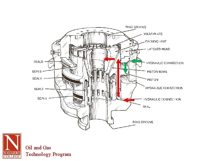
Annular Preventers • Also called bag or spherical preventers • Versatile pressure-control devices – Kelly – Drill collars – Drill pipe – Work string – Tubing – Wireline – Open hole (in an emergency) • Can act as a lubricating head when stripping (moving) pipe under pressure Oil and Gas Technology Program
Oil and Gas Technology Program
Packing Elements • Many sizes and pressure ratings • High-tensile rubber (Buna-N, neoprene) (Viton is an high-temperature resistant rubber) backed by steel fingers molded into the rubber • Manufacturer recommendations for rubber selection • Resistance against corrosion, sour gas and/or extreme cold Oil and Gas Technology Program
Abuse or Misuse of Packing Elements • Improperating pressure – Max pressure typically 1500 psi – Moving pipe at this pressure can cause damage • Closing pressure reduced to about 800 psi • Small fluid leak appears which helps lubricate the pipe as it’s moved • Do not close annular preventer on open hole or wireline unless absolutely necessary (excess stretch can permanently deform and/or abrade the element) • Pre-split elements are helpful when stripping pipe Oil and Gas Technology Program
Operations • More hydraulic fluid is needed to close annular preventer than ram preventer • More pressure doesn’t speed up the close • Larger lines, fittings and regulators (more fluid volume) can help • Improved operations – Store in cool dry place away from ozone (motors) – Never use higher pressure than necessary – Always test the packer when installed in the preventer – Check manufacturer’s manual for operating data Oil and Gas Technology Program
Annular BOP Maintenance • Inspection – missing rubber between or missing fingers – scratches or burrs (can be removed with fine grit sandpaper) • Wiper seals in good condition (especially check top seal) • Store rubber parts in cool, dry, dark place • H 2 S environment requires rubber to be trimmed to avoid stress-corrosion cracking • Be sure ringed grooves are clean and free of grease • Ensure that the preventer returns to its full open position after being closed • Replace all rubber elements at least annually Oil and Gas Technology Program
Ram Preventers • Two basic types – Pipe rams – seal around pipe – Blind (blank) rams – seal open hole • Steel blocks with elastomer sealing elements • Installed on opposite sides of preventer housing • Available in many sizes and pressures and as multiple unit to save vertical space Oil and Gas Technology Program
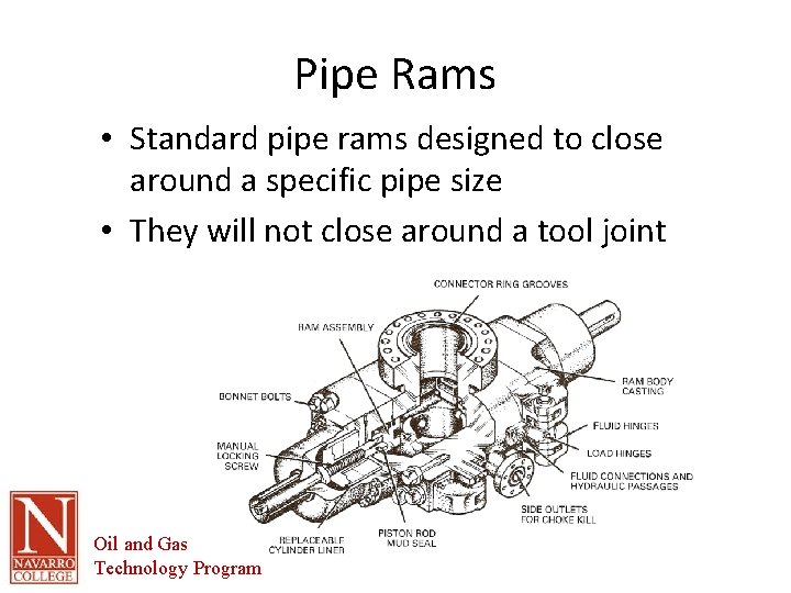
Pipe Rams • Standard pipe rams designed to close around a specific pipe size • They will not close around a tool joint Oil and Gas Technology Program
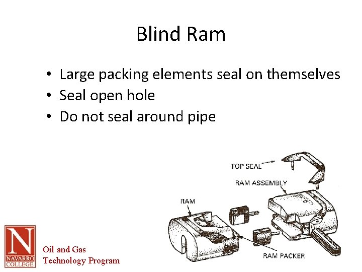
Blind Ram • Large packing elements seal on themselves • Seal open hole • Do not seal around pipe Oil and Gas Technology Program
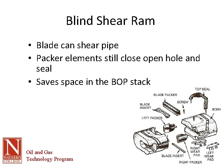
Blind Shear Ram • Blade can shear pipe • Packer elements still close open hole and seal • Saves space in the BOP stack Oil and Gas Technology Program
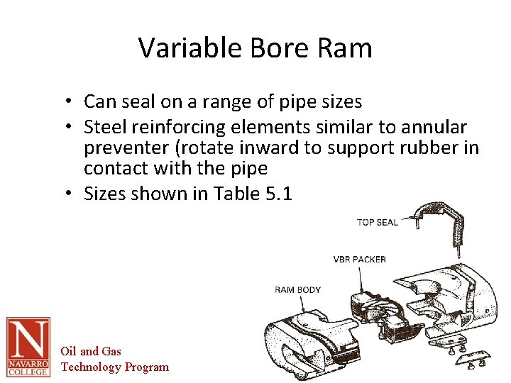
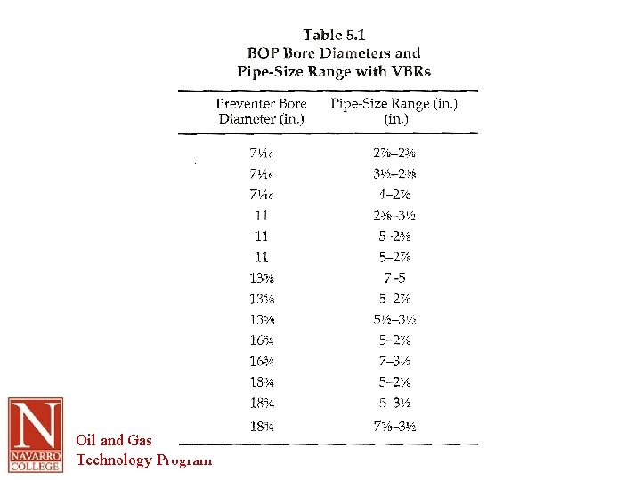
Variable Bore Ram • Can seal on a range of pipe sizes • Steel reinforcing elements similar to annular preventer (rotate inward to support rubber in contact with the pipe • Sizes shown in Table 5. 1 Oil and Gas Technology Program
Oil and Gas Technology Program
RAM Maintenance • Inspect and replace damaged or missing rubber elements • Replace bonnet seal whenever opened • Piston rods free from burrs, scratches, etc • Clean and refinish ram cavity • Check weep hole packing and replace as needed Oil and Gas Technology Program

Installation • Writing on housings should be right side up • Clean ring grooves and mating surfaces • Clean and defect-free flanges and sealing rings • Tight flange nuts on flanges • Center the BOP stack over the wellbore – Easy to say not always easy to accomplish – Can cause long-term damage to stack bore and/or ram faces and well bore • Pressure testing Oil and Gas Technology Program
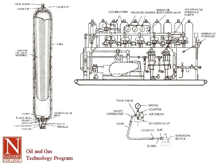
BOP Operating Units • Accumulator system • Operate rapidly and reliably when a kick occurs • Most operate at 3000 psig • Hydraulic fluid (or chemical and water mixture) in reservoir and in precharged (1000 psi) bottles • Flexible bladder separates the nitrogen gas from the fluid – WHY? ? Oil and Gas Technology Program
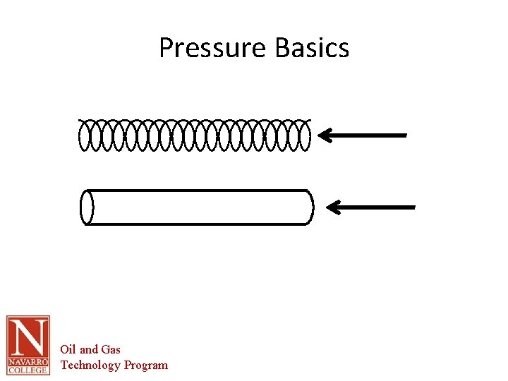
Pressure Basics Oil and Gas Technology Program
Oil and Gas Technology Program
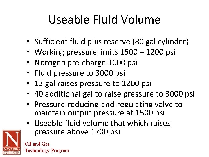
Useable Fluid Volume Sufficient fluid plus reserve (80 gal cylinder) Working pressure limits 1500 – 1200 psi Nitrogen pre-charge 1000 psi Fluid pressure to 3000 psi 13 gal raises pressure to 1200 psi 40 additional gal to raise pressure to 3000 psi Pressure-reducing-and-regulating valve to maintain output pressure at 1500 psi • Useable fluid volume that which raises pressure above 1200 psi • • Oil and Gas Technology Program
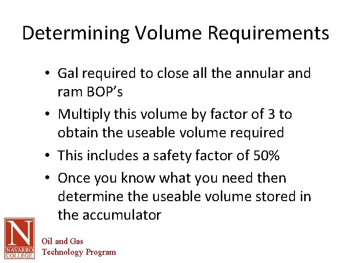
Determining Volume Requirements • Gal required to close all the annular and ram BOP’s • Multiply this volume by factor of 3 to obtain the useable volume required • This includes a safety factor of 50% • Once you know what you need then determine the useable volume stored in the accumulator Oil and Gas Technology Program
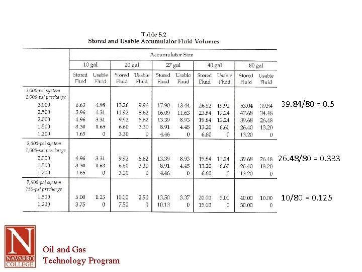
39. 84/80 = 0. 5 26. 48/80 = 0. 333 10/80 = 0. 125 Oil and Gas Technology Program
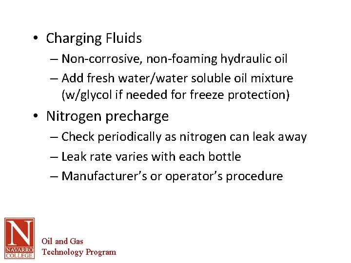
• Charging Fluids – Non-corrosive, non-foaming hydraulic oil – Add fresh water/water soluble oil mixture (w/glycol if needed for freeze protection) • Nitrogen precharge – Check periodically as nitrogen can leak away – Leak rate varies with each bottle – Manufacturer’s or operator’s procedure Oil and Gas Technology Program
Maintenance • Every 30 days or each time system is rigged up (whichever is sooner) • Clean, inspect, repair, lubricate • Steps listed on page 5 -10 • Guidance only each system has specific requirements – check manufacturer for details Oil and Gas Technology Program
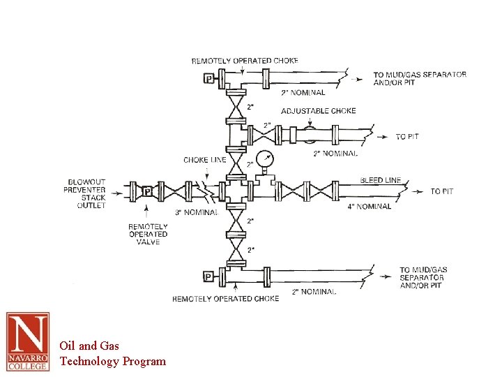
Choke Manifolds • Provide flow path for circulating fluid out of the BOP stack under controlled pressure • Manifold provides multiple paths for flow so choke can be replaced or repaired • RP 53 describes choke manifolds and give planning and installation guidelines • See list on page 5 -15. Oil and Gas Technology Program
Oil and Gas Technology Program
Chokes • Controls flow rate in a line • Restriction or orifice • Small choke provides more decrease than large choke but more back pressure • Well control chokes are designed to handle abrasive fluids • Manual chokes are available but most well control applications use remotely adjustable chokes • Choke and kill lines should be: – Inspected frequently – Short nipples with correct strength (Sch. 40, 80, etc) – Avoid low pressure hoses (bursting and bends) Oil and Gas Technology Program
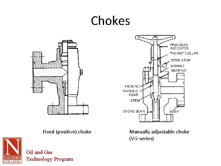
Chokes Fixed (positive) choke Oil and Gas Technology Program Manually adjustable choke (VG-series)
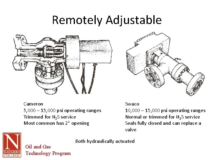
Remotely Adjustable Cameron 5, 000 – 15, 000 psi operating ranges Trimmed for H 2 S service Most common has 2” opening Oil and Gas Technology Program Swaco 10, 000 – 15, 000 psi operating ranges Normal or trimmed for H 2 S service Seals fully closed and can replace a valve Both hydraulically actuated
Gas-Handling Equipment • Vital part of any well control system • Removal of the gas from the fluid coming from the well allows for proper fluid handling downstream • Gas handling must include likelihood of gases that are explosive mixtures – Gas separators – Degassers Oil and Gas Technology Program
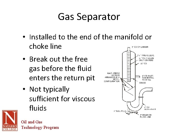
Gas Separator • Installed to the end of the manifold or choke line • Break out the free gas before the fluid enters the return pit • Not typically sufficient for viscous fluids Oil and Gas Technology Program
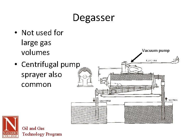
Degasser • Not used for large gas volumes • Centrifugal pump sprayer also common Oil and Gas Technology Program Vacuum pump
Safety Valves, Floats, Inside BOP’s • Basic requirement for well control is a method of closing off the work string – Safety valves – Floats – Inside Blowout Preventers • Usually handled by the floor crew • Safety valves – Upper kelly cocks – Safety valves Oil and Gas Technology Program
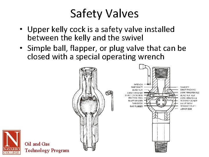
Safety Valves • Upper kelly cock is a safety valve installed between the kelly and the swivel • Simple ball, flapper, or plug valve that can be closed with a special operating wrench Oil and Gas Technology Program
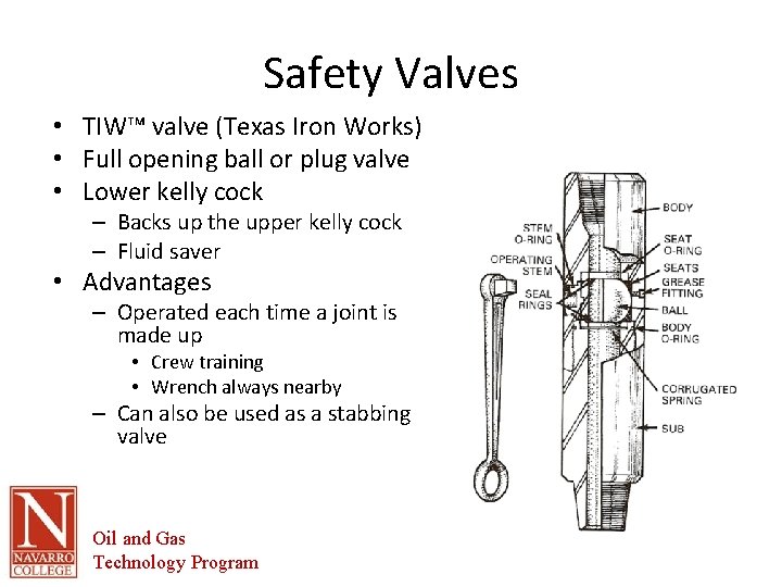
Safety Valves • TIW™ valve (Texas Iron Works) • Full opening ball or plug valve • Lower kelly cock – Backs up the upper kelly cock – Fluid saver • Advantages – Operated each time a joint is made up • Crew training • Wrench always nearby – Can also be used as a stabbing valve Oil and Gas Technology Program
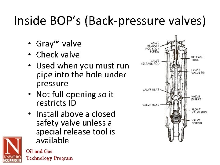
Inside BOP’s (Back-pressure valves) • Gray™ valve • Check valve • Used when you must run pipe into the hole under pressure • Not full opening so it restricts ID • Install above a closed safety valve unless a special release tool is available Oil and Gas Technology Program
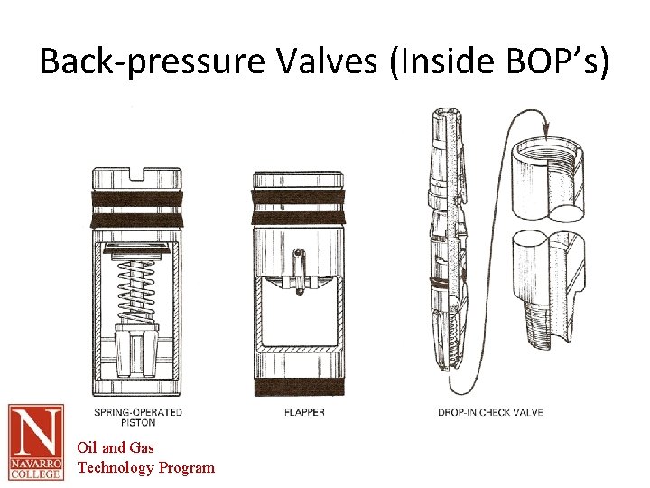
Back-pressure Valves (Inside BOP’s) Oil and Gas Technology Program
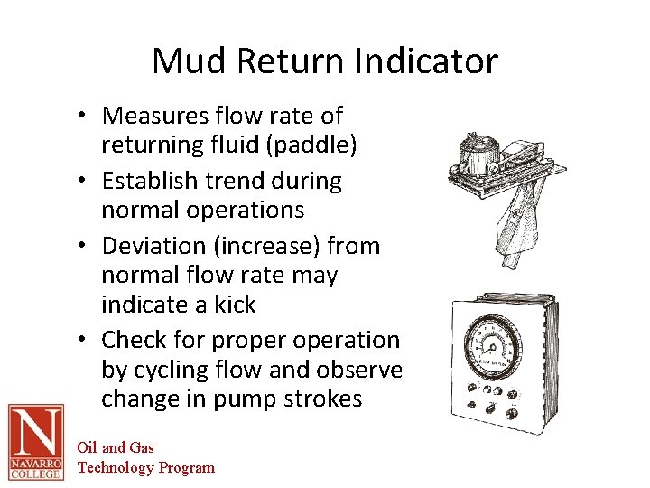
Mud Return Indicator • Measures flow rate of returning fluid (paddle) • Establish trend during normal operations • Deviation (increase) from normal flow rate may indicate a kick • Check for properation by cycling flow and observe change in pump strokes Oil and Gas Technology Program
Fluid Volume Measurement Basic kick warning instrument Combines flow sensor and a pump stroke counter Integrates the two to determine the volume Can also use a trip tank to directly measure the fluid displaced by one or more strings of pipe • Pit volume indicators use floats to determine the fluid level in each pit and integrate them to determine the total fluid volume • Gas detectors • • Oil and Gas Technology Program
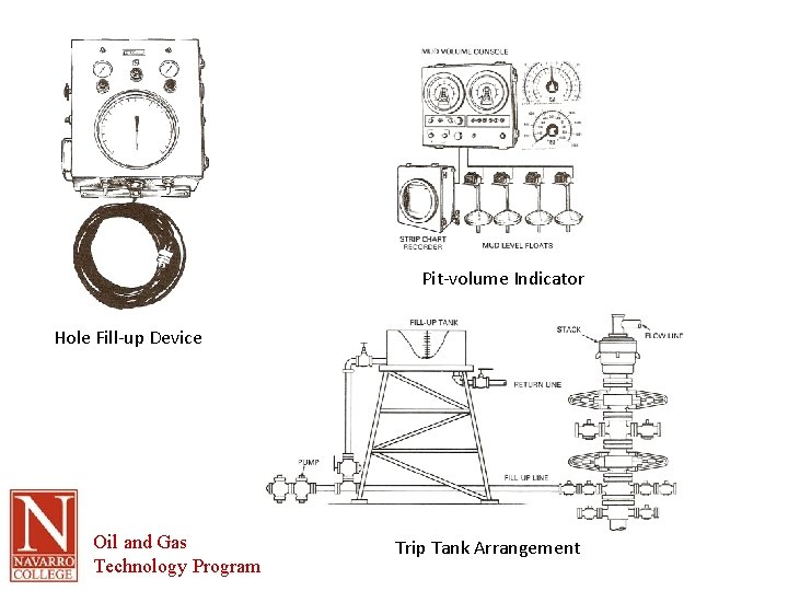
Pit-volume Indicator Hole Fill-up Device Oil and Gas Technology Program Trip Tank Arrangement
- Slides: 42