
PSS 1 overview Stuart Birch www europeanspallationsource se

PSS 1 overview Stuart Birch www. europeanspallationsource. se 1 st March 2017
Contents • Accelerator PSS Overview • PSS 1 Hardware • PSS Interfaces 2
Personnel Safety System • Safety interlock system – If the Beam is ON No Access – If Access is allowed No Beam permit – If Emergency Hard switch-off hazardous equipment • Access control system – Authorisation and authentication (databases, counters. . . ) – Access point systems (message display, card readers. . . ) • Radiation monitoring system – If radiation level high Emergency trip beam and alarm locally 3
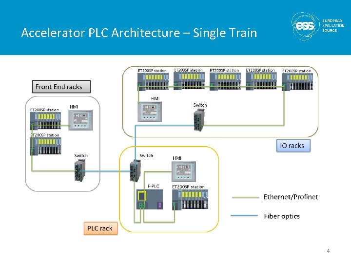
Accelerator PLC Architecture – Single Train 4
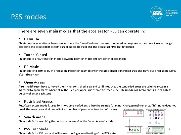
PSS modes There are seven main modes that the accelerator PSS can operate in: • Beam On This is normal operational beam mode where the formalised searches are completed, all keys are in the correct key exchange positions, the access door systems are disabled (locked) and the accelerator PSS permit issued. • Tunnel Closed This mode is a PSS transition mode between beam on mode and any other access mode • RP Mode This mode is to only allow the radiation protection team to enter the accelerator controlled area and carry out a radiation survey after a beam run. • Open Access After the RP team have surveyed the tunnel controlled area and confirmed that the controlled areas are safe the system is switched to open access where all authorised personnel can then enter the tunnel. This mode will break each zone search as personnel enter each zone • Restricted Access Restricted access mode is used for short time period entry into the tunnels for minor changes/maintenance. This mode does not break the searches and allows a limited number of personnel to enter with a key • Search mode This mode is for searching the controlled areas after the “open Access” mode. • PSS Test Mode This mode is for PSS test and will be used during annual testing of the PSS system. 5
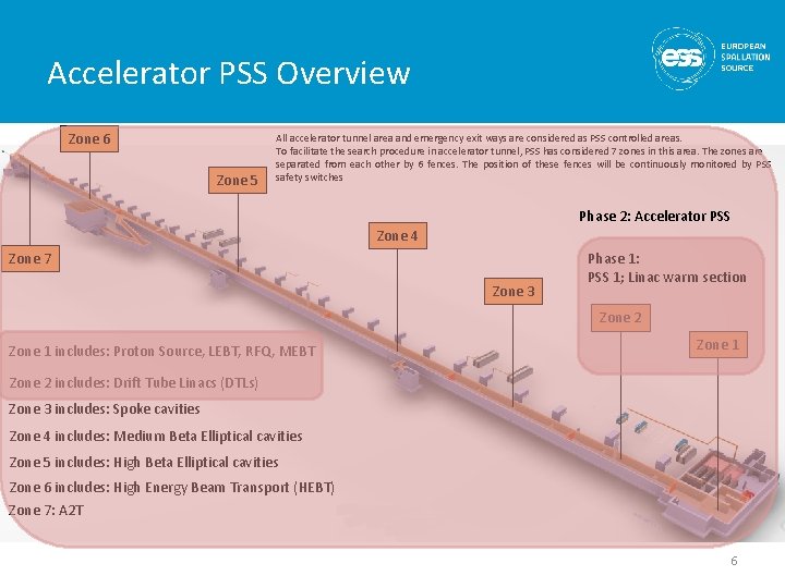
Accelerator PSS Overview All accelerator tunnel area and emergency exit ways are considered as PSS controlled areas. Zone 6 To facilitate the search procedure in accelerator tunnel, PSS has considered 7 zones in this area. The zones are separated from each other by 6 fences. The position of these fences will be continuously monitored by PSS Zone 5 safety switches Phase 2: Accelerator PSS Zone 4 Phase 1: Zone 7 PSS 1; Linac warm section Zone 3 Zone 2 Zone 1 includes: Proton Source, LEBT, RFQ, MEBT Zone 1 Zone 2 includes: Drift Tube Linacs (DTLs) Zone 3 includes: Spoke cavities Zone 4 includes: Medium Beta Elliptical cavities Zone 5 includes: High Beta Elliptical cavities Zone 6 includes: High Energy Beam Transport (HEBT) Zone 7: A 2 T 6

PSS 1 Overview. 7
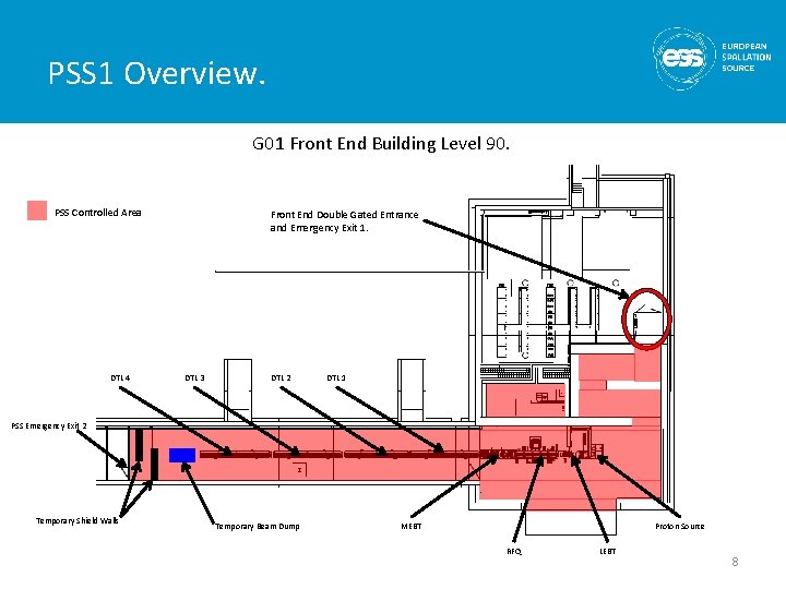
PSS 1 Overview. G 01 Front End Building Level 90. PSS Controlled Area DTL 4 Front End Double Gated Entrance and Emergency Exit 1. DTL 3 DTL 2 DTL 1 PSS Emergency Exit 2 Temporary Shield Walls Temporary Beam Dump MEBT Proton Source RFQ LEBT 8
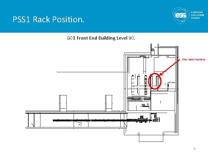
PSS 1 Rack Position. G 01 Front End Building Level 90. PSS 1 Rack Positions 9
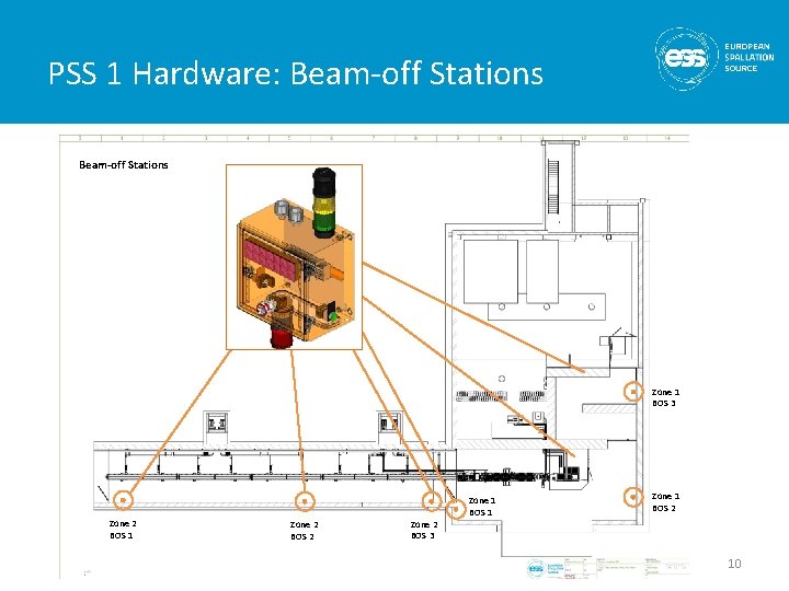
PSS 1 Hardware: Beam-off Stations PSS 1 Area Stations Plan View Beam-off Zone 1 BOS 3 Zone 2 BOS 1 Zone 2 BOS 2 Zone 2 BOS 3 Zone 1 BOS 1 Zone 1 BOS 2 10
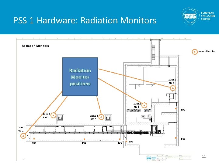
PSS 1 Hardware: Radiation Monitors PSS 1 Area Plan View Radiation Monitors Beam-off Station Radiation Monitor positions Zone 1 RM 2 Zone 1 RM 1 Zone 2 RM 2 BOS Zone 2 RM 3 Zone 2 RM 1 BOS BOS BOS 11
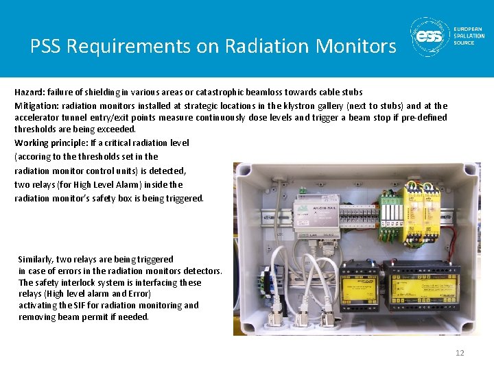
PSS Requirements on Radiation Monitors Hazard: failure of shielding in various areas or catastrophic beamloss towards cable stubs Mitigation: radiation monitors installed at strategic locations in the klystron gallery (next to stubs) and at the accelerator tunnel entry/exit points measure continuously dose levels and trigger a beam stop if pre-defined thresholds are being exceeded. Working principle: If a critical radiation level (accoring to the thresholds set in the radiation monitor control units) is detected, two relays (for High Level Alarm) inside the radiation monitor’s safety box is being triggered. Similarly, two relays are being triggered in case of errors in the radiation monitors detectors. The safety interlock system is interfacing these relays (High level alarm and Error) activating the SIF for radiation monitoring and removing beam permit if needed. 12
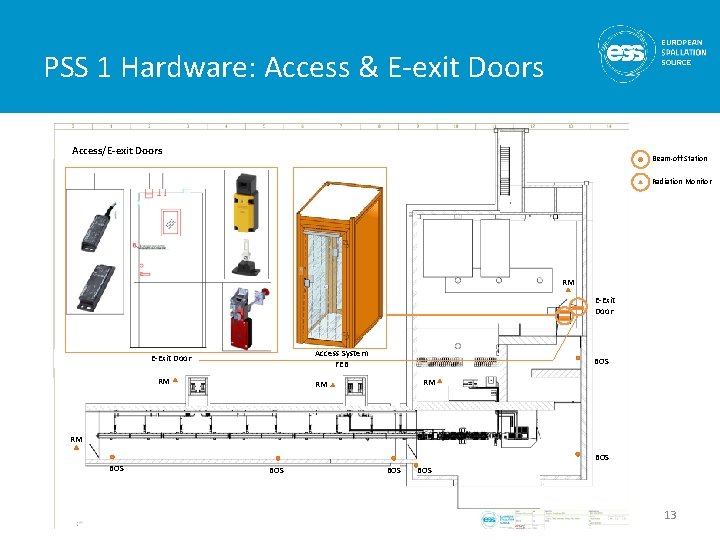
PSS 1 Hardware: Access & E-exit Doors PSS 1 Area Plan. Doors View Access/E-exit Beam-off Station Radiation Monitor + RM E-Exit Door Access System FEB E-Exit Door RM BOS RM RM RM BOS BOS 13
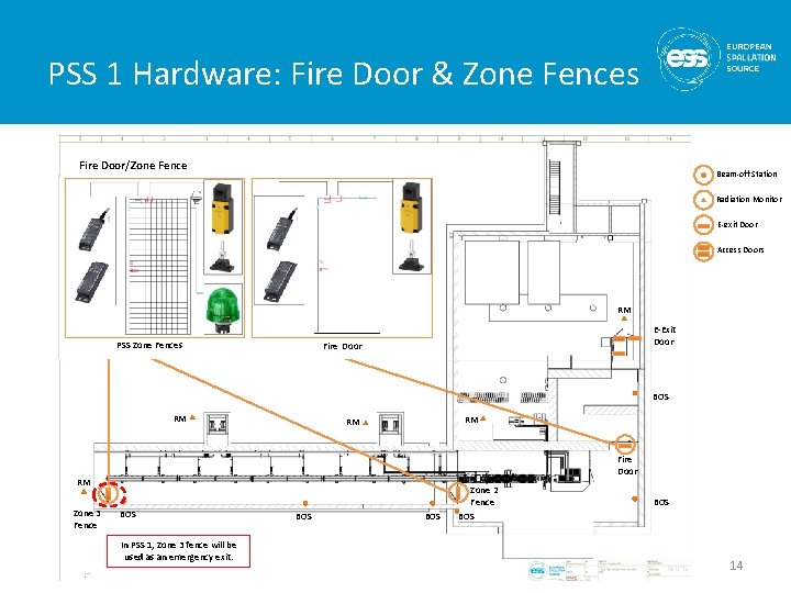
PSS 1 Hardware: Fire Door & Zone Fences PSS Area Plan View Fire 1 Door/Zone Fence Beam-off Station Radiation Monitor E-exit Door Access Doors + RM PSS Zone Fences E-Exit Door Fire Door BOS RM RM RM Fire Door RM Zone 3 Fence BOS In PSS 1, Zone 3 fence will be used as an emergency exit. BOS Zone 2 Fence BOS 14
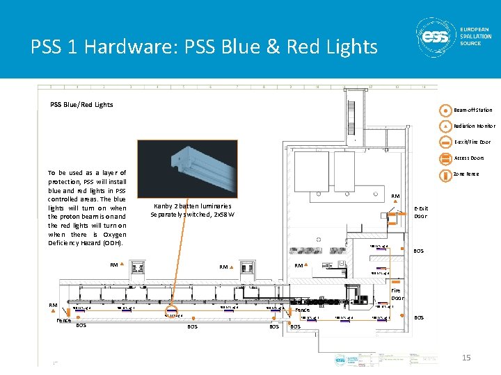
PSS 1 Hardware: PSS Blue & Red Lights PSS Area Plan. Lights View PSS 1 Blue/Red Beam-off Station Radiation Monitor E-exit/Fire Door + To be used as a layer of protection, PSS will install blue and red lights in PSS controlled areas. The blue lights will turn on when the proton beam is on and the red lights will turn on when there is Oxygen Deficiency Hazard (ODH). Access Doors Zone Fence RM Kanby 2 batten luminaries Separately switched, 2 x 58 W E-Exit Door PSS B/R Light RM BOS RM RM PSS B/R Light RM Fence Fire Door PSS B/R Light PSS B/R Light BOS BOS PSS B/R Light Fence PSS B/R Light BOS 15
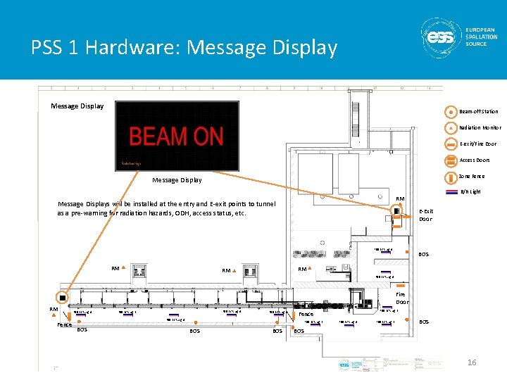
PSS 1 Hardware: Message Display PSS 1 Area. Display Plan View Message Beam-off Station Radiation Monitor E-exit/Fire Door + Access Doors Zone Fence Message Displays will be installed at the entry and E-exit points to tunnel as a pre-warning for radiation hazards, ODH, access status, etc. E-Exit Door PSS B/R Light RM BOS RM RM PSS B/R Light RM Fence Fire Door PSS B/R Light PSS B/R Light BOS BOS PSS B/R Light Fence PSS B/R Light BOS 16
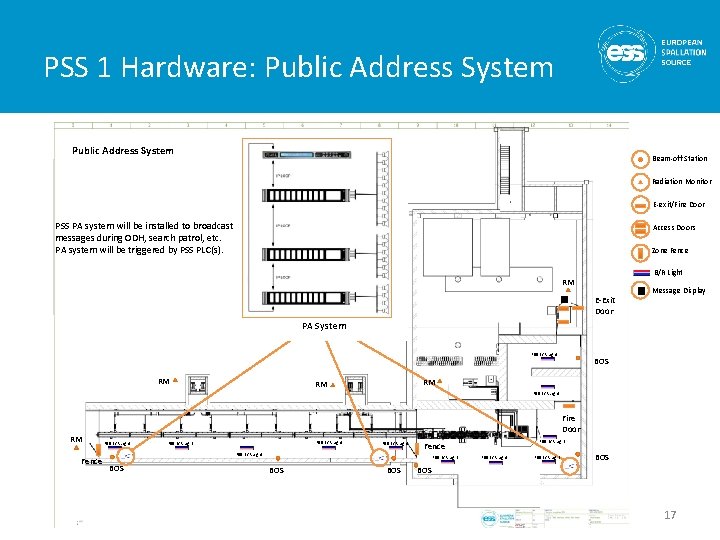
PSS 1 Hardware: Public Address System PSS 1 Area Plan View Public Address System Beam-off Station Radiation Monitor E-exit/Fire Door PSS PA system will be installed to broadcast messages during ODH, search patrol, etc. PA system will be triggered by PSS PLC(s). Access Doors Zone Fence + B/R Light RM E-Exit Door Message Display PA System PSS B/R Light RM BOS RM RM PSS B/R Light RM Fence Fire Door PSS B/R Light PSS B/R Light BOS BOS PSS B/R Light Fence PSS B/R Light BOS 17
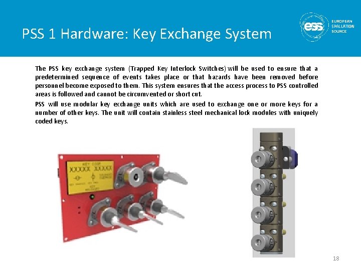
PSS 1 Hardware: Key Exchange System The PSS key exchange system (Trapped Key Interlock Switches) will be used to ensure that a predetermined sequence of events takes place or that hazards have been removed before personnel become exposed to them. This system ensures that the access process to PSS controlled areas is followed and cannot be circumvented or short cut. PSS will use modular key exchange units which are used to exchange one or more keys for a number of other keys. The unit will contain stainless steel mechanical lock modules with uniquely coded keys. 18
PSS Interfaces • PSS will stop the accelerator proton beam by removing mains electrical power from following systems: – The Ion source plasma generator system – The Ion source extraction system – The RFQ modulator system • PSS will remove mains electrical power from the following systems to mitigate against X-ray hazards when there is access to tunnel: – – – • MEBT bunchers (3 units) Drift Tube Linacs (5 units) Spoke cavities (26 units) Elliptical medium beta cavities (9 units) Elliptical high beta cavities (21 units) PSS will interface with two bending magnets which send the beam towards Target. 19
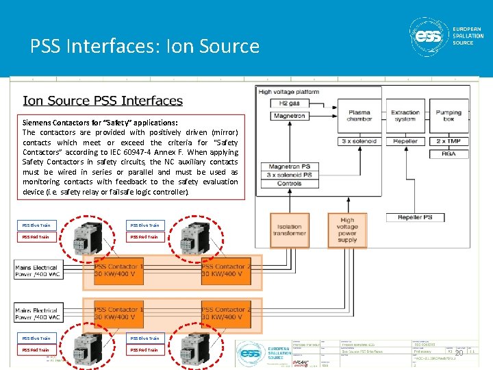
PSS Interfaces: Ion Source Siemens Contactors for “Safety” applications: The contactors are provided with positively driven (mirror) contacts which meet or exceed the criteria for "Safety Contactors” according to IEC 60947 -4 Annex F. When applying Safety Contactors in safety circuits, the NC auxiliary contacts must be wired in series or parallel and must be used as monitoring contacts with feedback to the safety evaluation device (i. e. safety relay or failsafe logic controller). PSS Blue Train PSS Red Train 20
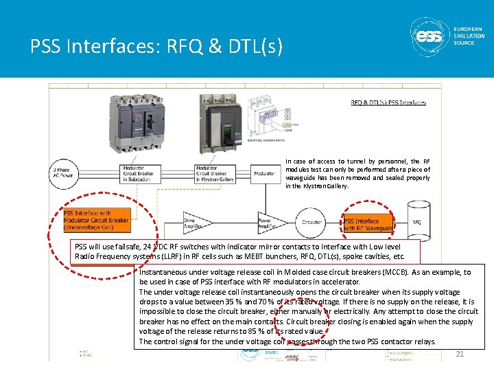
PSS Interfaces: RFQ & DTL(s) In case of access to tunnel by personnel, the RF modules test can only be performed after a piece of waveguide has been removed and sealed properly in the Klystron Gallery. PSS will use failsafe, 24 VDC RF switches with indicator mirror contacts to interface with Low level Radio Frequency systems (LLRF) in RF cells such as MEBT bunchers, RFQ, DTL(s), spoke cavities, etc. Instantaneous under voltage release coil in Molded case circuit breakers (MCCB). As an example, to be used in case of PSS interface with RF modulators in accelerator. The under voltage release coil instantaneously opens the circuit breaker when its supply voltage drops to a value between 35 % and 70 % of its rated voltage. If there is no supply on the release, it is impossible to close the circuit breaker, either manually or electrically. Any attempt to close the circuit breaker has no effect on the main contacts. Circuit breaker closing is enabled again when the supply voltage of the release returns to 85 % of its rated value. The control signal for the under voltage coil passes through the two PSS contactor relays. 21

Thank you for your attention!
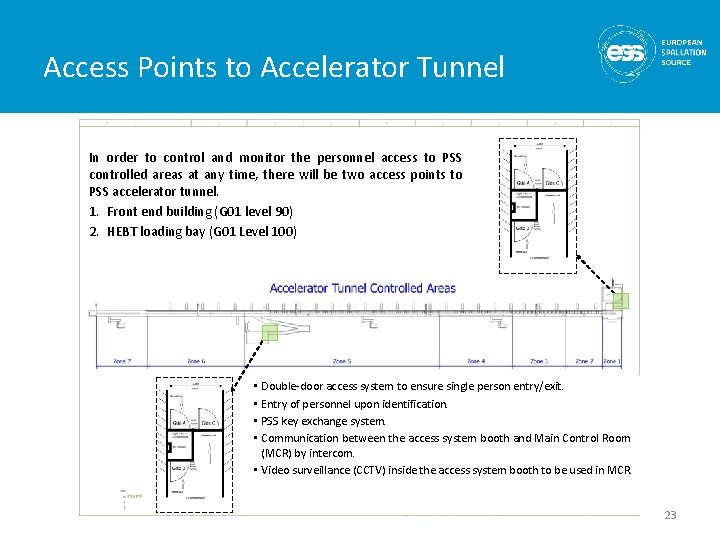
Access Points to Accelerator Tunnel In order to control and monitor the personnel access to PSS controlled areas at any time, there will be two access points to PSS accelerator tunnel. 1. Front end building (G 01 level 90) 2. HEBT loading bay (G 01 Level 100) • Double-door access system to ensure single person entry/exit. • Entry of personnel upon identification. • PSS key exchange system. • Communication between the access system booth and Main Control Room (MCR) by intercom. • Video surveillance (CCTV) inside the access system booth to be used in MCR. 23
- Slides: 23